Lowenthal G., Airey P. Practical Applications of Radioactivity and Nuclear Radiations
Подождите немного. Документ загружается.

. The radiotracer should behave identically in essential respects to the component of
the syst em which is under study.
. Consistent with the aims of the investigation, a shorter rather than a longer lived
radionuclide should be chosen.
. If practical, it is preferable to choose radionuclides emitting g rays in the range 150
to about 500 keV; at higher energies there are greater problems in handling and
transport.
The process of choosing an appropriate radiotracer will be illustrated with
examples from environmental and industrial applications.
Water tracing
On the face of it, the use of HTO (tritiated water) as a tracer for water or
aqueous systems would appear to be an obvious choice. However, tritium is a
very low-energy b particle emitter (E
max
= 18.6 keV) and hence its activity
8.2 Tracer applications in the ®eld 241
241
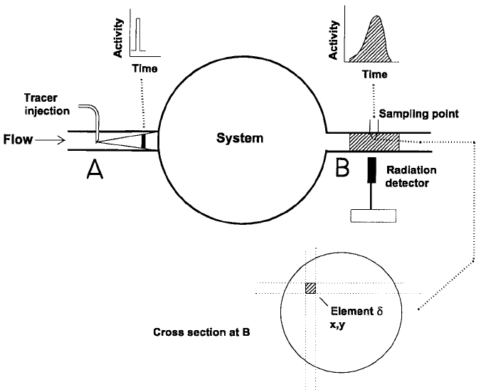
Figure 8.1. The principle of a tracer investigation. Radiotracers are used to track
individual components of complex systems. A tracer is injected at A and its response
monitored at B and interprete d in terms of the information sought on the behaviour
of the system. The location of the radiation detector and the sampling point d is
shown.
cannot be measured in situ. Samples must be collected and returned to the
laboratory for analysis. If data are required in real time, gamma ray emitting
isotopes such as bromide (
82
Br), iodide (
131
I) or sodium pertechnetate (
99m
Tc)
must be used. Nuclear decay properties are listed in Table 8.1 and ¯ow rate
measurements are discussed in Section 8.3.
Sand and sediment tracing
To investigate the transport of sand and sediments, it is necessary to match
the particle size distributions and density of the natural material with those of
the radiotracer. Two methods are commonly used. The ®rst is preferred for
®ne sediments. Samples are collected from the study area and made up as a
slurry. A dissolved radioactive tracer such as
198
Au, which adsorbs strongly
onto the surface, is added in a shielded apparatus. Although the physical
properties of the tracer will match those of the natural material, there may be
problems in assuring the integrity of the label over the period of the
investigation.
The second method is widely used in sand tracing. It involves the synthesis
of glass beads with a particle size distribution and density matching that of
the sand. The glass incorporates the required target material (e.g. lanthanum
oxide, iridium or silver metal) which is irradiated in the reactor to form the
tracer (
140
La,
192
Ir or
110m
Ag, see Table 8.1). The integrity of the label is not
in question. However, there may be problems in matching the particle size
distributions.
In both cases the radiotracer is released to the area under investigation and
its behaviour monitored by means of the emitted radiations. As noted earlier,
the half life of the isotope should be as short as possible consistent with the
aims of the investigation. For instance,
198
Au (T
1/2
= 2.70 d), is commonly
used for studies which take up to a week;
192
Ir (T
1/2
= 73.8 d) for one or two
seasons; and
110m
Ag (T
1/2
= 249.8 d) for investigations which extend over a
complete annual cycle.
Industrial tracing
Industrial applications provide numerous examples of the need to optimise
the choice of radiotracers. In the oil re®ning industry, for instance, it is
frequently necessary to employ tracers in chemical forms which are soluble in
hydrocarbons but will not be extracted from the hydrocarbon into the
aqueous phase.
In the study of blast furnaces (Section 8.4.3), the metallic tracers gold-198
and cobalt-60 have long been used to trace the iron, and lanthanum oxide
(
140
La) to simultaneously trace the slag which is a mixture of oxides. Other
Applications of tracer technology to industry and the environment242
investigations require gas tracers and
85
Kr (Table 8.2), a chemically inert
noble gas, is commonly used. In some applications
41
Ar, another noble gas, is
preferred as it has a short half life (1.83 h) and emits 1.3 MeV g rays (100%).
However, its short half life restricts applications to sites suf®ciently close to a
nuclear reactor.
8.2.3 Isotope injections
The isotope injection system should be designed to minimise the dose to
personnel while maximising the amount of information gained from the
investigation. Very short duration (instantaneous) injections are normally
preferred because the experimental arrangement and the subsequent inter-
pretation of the measured data are relatively simple. Occasionally, there is a
need to inject a tracer into the system at a constant rate over the entire
duration of the investigation. Examples of both these procedures will be
presented later in this chapter.
8.2.4 Tracer detection and monitoring in the ®eld
Field monitoring systems
These systems comprise radiation detectors, ratemeters and either data
loggers or output devices. When working with X or g rays, NaI(Tl) crystals
optically coupled to a photo-multiplier tube and associated electronics are
almost universally used as radiation detectors because they are relatively
cheap, ef®cient and robust. Either 50650 mm or 25625 mm crystals are
usually used. There is, as a rule, little incentive to use larger crystals because,
as described below, the bulk of the signal is scattered radiation with energies
below 150 keV. At these energies, the absorption ef®ciencies approach 90%
even when using 25625 mm crystals (Figure 4.4).
The radiation detector (Figure 8.2) is mounted in a cylindrical aluminium
or stainless steel case. Although more rugged, a stainless steel housing
absorbs a higher proportion of the low-energy radiation than aluminium.
The loss of ef®ciency could exceed 50% and practitioners may thus need to
chose between enhanced ef®ciency and reduced ruggedness.
The instrumentation required for routine work with NaI(Tl) crystals was
described in Section 4.3.1. With ®eld equipment, the electronics are usually
stand-alone units including ampli®ers, discriminators and ratemeters oper-
ated by a battery. The data are frequently stored for `on-line' or later transfer
to computers or other output devices.
8.2 Tracer applications in the ®eld 243
The role of scattered radiation in the monitoring of radiotracers
One of the challenges of ®eld investigations is to obtain the required
information with the minimum quantity of radioactive material. Careful
thought must be given to all aspects of the investigation from the conceptual
design to the ef®ciency of detection of the radiotracer.
In many ®eld investigations, the detection ef®ciency of a gamma emitting
tracer is enhanced by counting the low-energy Compton scattered radiation.
Applications of tracer technology to industry and the environment244
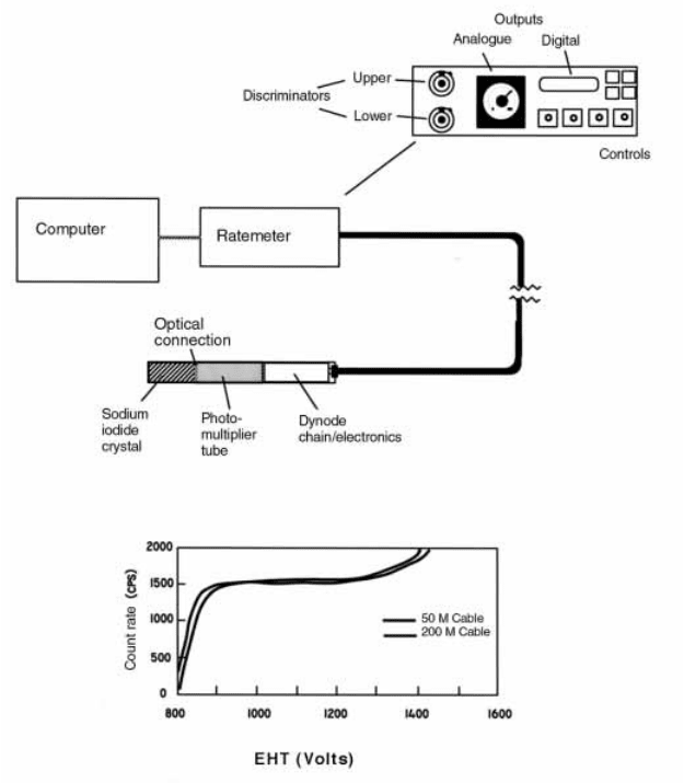
Figure 8.2. Schematic representation of ®eld monitoring equipment. This system
comprises a ®eld detector with a Na(Tl) de tector, photo-multiplier tube and
associated electronics. The ampli®ed pulse is fed into the ratemeter which may be
controlled by a computer. The ratemeter has an upper and lower discriminator and
an analogue and digital output. The variation of the countrate response to the
applied voltage which determines the counting plateau is shown.
The scattering mechanism leads to a signi®cant build-up in the number of
detectable g rays, as shown in Figure 4.6(b) and discussed in Section 4.4.4.
There is consequently a net gain in the sensitivity of the counting system to
the tracer (Section 4.4.1). However, there is a price to pay. Spectral informa-
tion that can only be obtained from an analysis of countrates in the full
energy peak is largely lost. This is not important if, as is often the case, only a
single radiotracer is involved.
The measurement of scattered radiation involves integral counting techni-
ques. The lower level discriminator is adjusted to accept as much of the low-
energy radiation as possible while avoiding noise pulses which could become
signi®cant when detecting pulse heights below a few millivolts. The setting of
the upper level discriminator is adjusted to maximise the signal to back-
ground ratio. Readers are referred to Section 4.4.2 and Figure 4.7 for further
information.
System checks and calibrations should be undertaken under conditions as
close as possible to those in the ®eld. The location of the counting plateau,
and hence the operating voltage (Figure 8.2) depends on the characteristics of
the detector, and also on the energy of the absorbed radiation. It is therefore
common practice to establish the plateau position with an americium-241
source as its 59.5 keV g ray is comparable in energy to much of the scattered
radiation. Another option is to place a sample of the radiotracer in a thin lead
pot and set the plateau using the degraded radiation emitted from the surface.
Accurate ®eld measurements
Radioisotope investigations are becoming increasingly sophisticated, re-
quiring good quantitative data. Procedures for accurate activity measure-
ments in laboratories were discussed in Sections 6.3 and 6.4. The accuracy of
®eld measurements depends on the quality of the calibration of the detector
and this is normally limited by the need to reproduce in the laboratory the
counting geometry which is found in the ®eld.
Three classes of counting geometry may be distinguished:
. quasi-in®nite geometry, when the detector is completely immersed in a large
volume of liquid such as industrial tanks, rivers or lakes;
. quasi-planar geometry, when the detector is mounted, for instance, on a sled a few
centimetres above labelled sediment on the bed of an estuary; and
. quasi-linear geometry when the detector is mounted external to a pipeline.
These are limiting cases which are discussed in the following chapter and
illustrated in Figures 9.2(a) to 9.2(c) respectively.
8.2 Tracer applications in the ®eld 245

8.3 Applications of tracer technology to ¯ow studies
8.3.1 General principles
Introduction
A general description of the application of tracers to scienti®c and engi-
neering investigations was given in Section 8.2.1. Fluid dynamics, to be
introduced in this section, has been one of the most fruitful ®elds of
application. Three classes of investigations are listed in Table 8.4.
Residence time distribution (RTD)
The concept of the residence or transit time of a ¯uid particle which is being
transported through a dynamic system (for instance, a chemical reactor, a
section of pipeline or the reach of a river) is fundamental to many industrial
and environmental applications. In particular, the residence time distribution
(RTD), which is de®ned below, is often used to specify the performance of
vessels designed for ef®cient chemical or bio-chemical engineering processing.
Tracer techniques have been developed to measure the RTD of such vessels
and to con®rm their speci®cations (Sections 8.3.7 to 9).
Let us assume that a ¯uid ¯ows through a system from an inlet (A) to an
exit pipeline (B) (Figure 8.1). If a radiotracer is injected at A as a point
source, the subsequent response of a detector at B will be a dispersed pulse
since no two particles of ¯uid have identical transit or residence times. The
distribution of transit times of all particles comprising the bulk ¯uid ¯owing
through the tank is described as the RTD. It will be shown in Eq. (A4.3) of
Applications of tracer technology to industry and the environment246
Table 8.4. Fluid dynamic investigations based on tracer dilution and mixing.
Investigation Measurement Mixing conditions Comments
Dispersion Dispersivities
and/or
dispersion
coef®cients
Not ap plicable Concentration pro®les
monitored as a function
of distance from point of
injection (Section 9.3.3)
Flow rate
measurements
Volume ¯ow
and/or mass
¯ow
Complete mixing at
the measurement
cross section
Sections 8.3.2 to 8.3.6
Residence time
studies
Residence time
distribution
(RTD)
Complete mixing at
the inlet and the
outlet of the vessel
Readily achieved if inlet
and outlet comprise
narrow pipelines
(Sections 8.3.7 to 8.3.9)
Appendix 4, that the countrate response of the detector at B is a direct
measure of the RTD of the tracer (and ¯uid) particles provided that
the tracer is injected as an instantaneous pulse, and
the bulk ¯ow rate through the tank is constant
This simple result is the basis of many radiotracing applications to the
chemical, re®ning and minerals processing industries where the ef®ciency of a
process depends on the contact times between different reagents (Section
8.3.9).
Mean residence time (MRT)
The mean residence time (MRT) is the average time taken by the tracer (and
¯uid) particles to travel between the injection and measurement points. If
there is an instantaneous injection at A, and a sharp response at B (Figure
8.1), the MRT is the time interval between the two. In more complex
situations, the MRT is calculated from an analysis of pulse shapes as noted in
Section 8.3.3 and in Appendix 4.
Complete mixing
A pulse of activity injected into a pipeline or a river is transported by
advection (i.e. it moves with the ¯uid ¯ow) and simultaneously disperses in
three dimensions (Section 9.3.3). The effect of ¯ow boundaries such as the
walls of a pipeline or the banks of a river is to restrict the scale of turbulence
and to induce mixing. The degree of mixing increases with distance from the
injection point. As discussed below, the concept of complete mixing of the
tracer with the bulk ¯ow is extremely important. Complete mixing is achieved
when the radiotracer concentration is everywhere the same following a
continuous injection at a constant rate into a constant ¯ow. However, pulse
injections are usually favoured over continuous tracer injections because they
generate the required information with the use of much less radiotracer.
Under these conditions, tracer concentrations are nowhere constant, and the
criterion for complete mixing may be expressed in one of the following ways.
(1) If the ¯uid is sampled at a constant rate (location B, Figure 8.1), complete mixing
is achieved if the total amount of tracer removed during the passage of the entire
radioactive pulse is independent of the sampling point (element d ) on the
measurement cross section.
(2) If a detector is located within the ¯uid, complete mixing is achieved if the total
number of counts (corrected for background and detector ef®ciency) registered
during the passage of the plume is independent of its location (Figur e 8.1) on the
measurement cross section.
8.3 Flow studies 247

Further details are presented in Appendix 4. Tracer dilution techniques can
be used to determine ¯ow rates in a simple and direct manner provided
complete mixing has been achieved. Herein lies the signi®cance of the
concept. It follows that the related concept of `mixing length' or the distance
from the point of injection until mixing is essentially complete is of consider-
able practical importance. A number of formulae have been developed to
determine mixing lengths, some of which are listed in Table 9.3.
8.3.2 Flow rate measurements: an overview
There are two fundamentally different approaches to measuring ¯ow rate: the
pulse velocity (`point to point') method and tracer dilution techniques. The
tracer dilution techniques may themselves be sub-divided according to the
nature of the injection and of the measurement methods as shown below
Flow rates may be obtained using tracer techniques without interfering
with plant operation. Further, the ¯uid may be corrosive, and may be in the
liquid or gaseous state or even multi phase. However a disadvantage is that
the measurements are specialised and expensive and refer only to the
conditions prevailing during the passage of the pulse past the monitoring
points. Tracer techniques are therefore mainly used to calibrate installed
metering systems designed for continuous readings.
8.3.3 Flow rate measurements: transit time techniques
Pulse velocity method
Conceptually, the pulse velocity method is the simplest and most widely used
technique. A radioisotope pulse is injected into a system at X and its rate of
Applications of tracer technology to industry and the environment248
Flow rate measurements
Pulse velocity method Tracer dilution methods
(Section 8.3.3) (Section 8.3.4)
Pulse injection Constant rate injection
Total sample method Total count method
(Sections 8.3.5 and 9.3.2) (Sections 8.3.6 and 9.3.2)
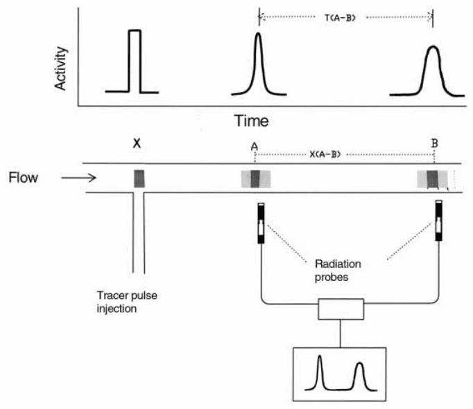
traverse between two appropriately selected points, A and B, is measured
with externally located detectors (Figure 8.3).
The average velocity of the pulse, V
A±B
, is given by
V
A±B
x
B±A
/T
B±A
(8.1)
where x
B±A
is the distance between detectors located respectively at A and B,
and T
B±A
is the corresponding transit time. Normally, the interval between
the pulse maxima is an adequate measure of the transit time for the passage
of the pulse. However, for greatest precision, T
A
and T
B
are individually
calculated from the shape of the response curves under conditions of
complete mixing (Appendix 4, Eq. (A4.5)). To calculate the volume ¯ow
Q
A±B
from the linear velocity V
A±B
, it is necessary to know the cross sectional
area of the pipeline.
The method is extensively used for both liquid and gas velocity measure-
8.3 Flow studies 249
Figure 8.3. Flow rate measurements: the pulse velocity or `point to point' method.
The tracer pulse is monitored at two locations following an instantaneous injection.
Normally, the pulse maxima are adequate to de®ne the interval T
A±B
. For the most
accurate work, the pulse pro®les must be analysed.
ments. For rapidly ¯owing ¯uids, the time interval between pulse measure-
ments at A and B may be as short as a few milliseconds, and fast response
detectors are necessary. An example is presented in Section 8.4.2.
Correlation methods
Cross correlation methods for measuring the velocity of two-phase ¯uids in
pipelines were ®rst proposed by Le Guennec et al. (1978). The method is
based on the fact that multi phase ¯uids are not homogeneous and periodi-
cally exhibit short-term ¯uctuations in density. These characteristic density
¯uctuations can be monitored by two or more density gauges located at
known intervals along the pipeline. By correlating the responses of the
gauges, estimates may be made of the transit times and hence the ¯ow
velocities. Unlike the radiotracer method for point to point velocity measure-
ments, signi®cant data processing is required. However, an advantage over
the tracer method is that the results may be collected continuously, and this
opens up the possibility for on-line process control. Readers are referred to
Chapter 5 (Section 5.12) of IAEA (1990a) for further information.
8.3.4 Flow rate measurements: tracer dilution methods
Introduction
Tracer dilution methods are widely used to measure the ¯ow rates of liquids
and gases. In contrast to the peak to peak method, volume ¯ow rates may be
calculated without knowledge of the cross sectional area of ¯ow provided
complete mixing has been achieved. Dilution methods are therefore well
suited to measurements of the ¯ow rates of rivers (Section 9.3.2). The tracer
may be injected at a constant rate or as a pulse. Two variants of the pulse
injection method, namely the total sample and total count methods, are
introduced below and discussed in Appendix 4.
Tracer injection at a constant rate
Tracer of speci®c activity C
0
(Bq/l) is injected at a constant ¯ow rate q (l/s)
into a pipeline or stream in which the ¯ow rate is Q (l/s). After complete
mixing has been achieved, the diluted tracer is sampled and the activity c (Bq/
l) measured (Figure 8.4). Since the mass, i.e. the activity of the tracer must be
conserved, one has:
qC
0
Q qc: (8.2)
Normally Q4q, and hence the volume ¯ow rate is given by:
Applications of tracer technology to industry and the environment250