Lindemann Peter A. Секреты свободной энергии - холодное электричество
Подождите немного. Документ загружается.

43
Verifying Tesla's Secret
bottom connection of the light bulb with his
finger. As soon as he did this, the light bulb
filament lit to full brightness in our hands. I
was about six feet away from the magnifying
transmitter and Tom was about eight feet
away. I felt no unusual sensations at all, but I
was quite startled. At that time I had no idea
how really safe this form of energy is.
To summarize, Tesla accidentally
discovered an electrostatic "super-charging"
effect while trying to verify Hertz' discovery
of electro-magnetic waves. After hundreds of
experiments, he learned how to control and
maximize this phenomenon. This led him to
the discovery that electricity is made up of
different components, that can be separated
from each other, and that a pure, gaseous
etheric energy can be fractionated away from
the flow of electrons in a circuit designed to
produce short duration, unidirectional
impulses. When all the conditions were right,
this gaseous, etheric energy would manifest
itself as a spatially distributed voltage that
would radiate away from the electrical circuit
as a "light-like ray" that could charge other
surfaces within the field.
From now on, I would like to refer to
this phenomenon as "The Electro-Radiant
Event" and summarize its characteristics as
follows:
• The Electro-Radiant Event is produced
when a high-voltage, direct current is
discharged across a spark-gap and
interrupted abruptly before any reversals
of current can occur.
• The Electro-Radiant Event leaves wires
and other circuit components
perpendicular to the flow of current.
• The Electro-Radiant Event produces a
spatially distributed voltage that can be
thousands of times higher than the initial
spark discharge voltage.
• It propagates instantaneously as a
longitudinal, electrostatic "light-like ray"
that behaves similarly to an
incompressible gas under pressure.
• Electro-Radiant effects are solely
characterized by impulse duration and
voltage drop in the spark gap.
• Electro-Radiant effects penetrate all
materials and create "electronic
responses" in metals like copper and
silver. In this case, "electronic
responses" means that an electrical
charge will build up on copper surfaces
exposed to Electro-Radiant emissions.
• Electro-Radiant impulses shorter than
100 microseconds are completely safe to
handle and will not cause shock or harm.
• Electro-Radiant impulses shorter than
100 nanoseconds are cold and easily
cause lighting effects in vacuum globes.
The "Electro-Radiant Event" is essentially
the "gain mechanism" that Tesla discovered
that is the basis of his Magnifying
Transmitter. It is the foundation of his claim
that he was able to create more energy in his
output than it took to initiate it in his input.
• This effect is greatly increased when the
source of direct current is a charged
capacitor.

44
Summary of The Electro-Radiant Event
1. The Electro-Radiant Event is produced when a high-voltage, direct
current is discharged across a spark gap and interrupted abruptly
before any reversals of current can occur.
2. This effect is greatly increased when the source of direct current is
a charged capacitor.
3. The Electro-Radiant Event leaves wires and other circuit
components perpendicular to the flow of current.
4. The Electro-Radiant Event produces a spatially distributed voltage
that can be thousands of times higher than the initial spark
discharge voltage.
5. It propagates instantaneously as a longitudinal, electrostatic "light-
like ray" that behaves similarly to an incompressible gas under
pressure.
6. Electro-Radiant effects are solely characterized by impulse duration
and voltage drop in the spark gap.
7. Electro-Radiant effects penetrate all materials and create
“electronic responses” in metals like copper and silver. In this case,
“electronic responses” means that an electrical charge will build up
on copper surfaces exposed to Electro-Radiant emissions
8. Electro-Radiant impulses shorter than 100 microseconds are
completely safe to handle and will not cause shock or harm.
9.
Electro-Radiant impulses shorter than 100 nanoseconds are cold
and easily cause lighting effects in vacuum globes.
Figure 25
45
46
Figure 26 Gray's Circuit "Schematic" and the Simplified Gray's Circuit
"Schematic"
47
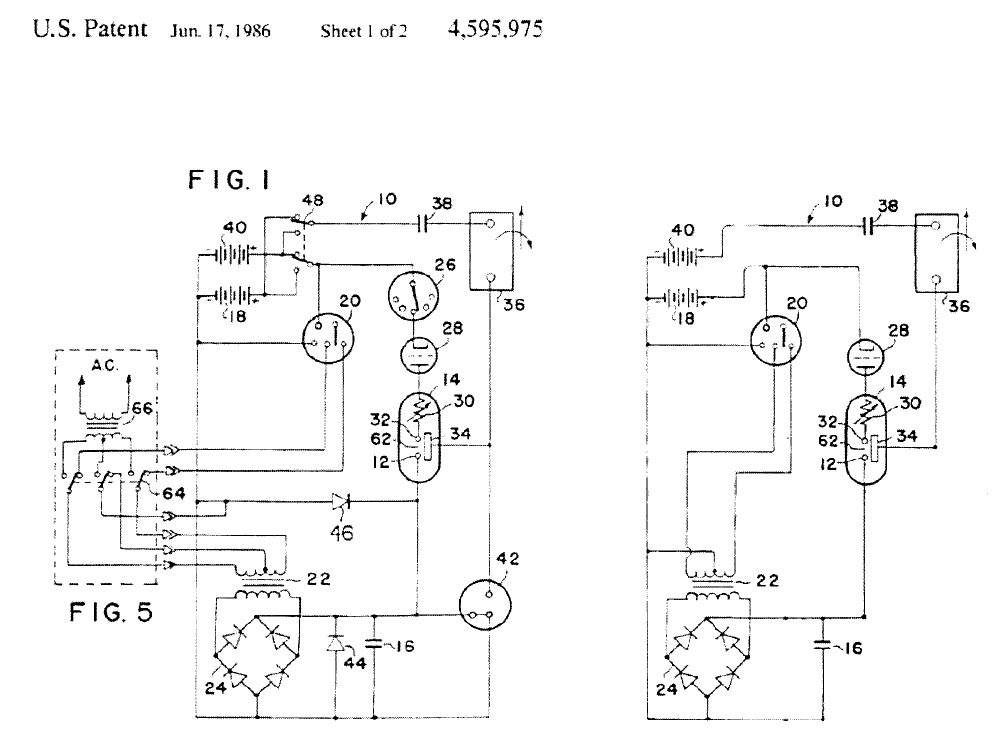
Chapter 4: Decoding Gray's Patents
In the previous chapters, I have taken a
great deal of time to explain the intricacies of
Tesla's Magnifying Transmitter because of
how it directly relates to the operation of Ed
Gray's cold electricity circuit. To better
understand what his circuit is and how it
operates, Figure 26 shows Gray's
"schematic" on the left, as it is presented in
Patent # 4,595,975, and on the right, it shows
what I refer to as the "Simplified Gray
Circuit `Schematic."' (I'm using the term
"schematic" in quotes because this is not
entirely a schematic diagram.) In order to
better understand this circuit in its most
fundamental form, I would like to eliminate a
number of components, temporarily, that
serve functions outside of its essential
operation, as follows:
• Components # 64 and #66 (shown
within the dotted-line box) indicate an
alternate way of running the circuit
from an AC supply. These parts can be
eliminated without changing the circuit
in any significant way because the
circuit can be run from the batteries.
• Components # 42, # 44, and # 46, which
are the safety overshoot mechanisms
referred to earlier, can be eliminated
because we learned in Chapter 1,
reading from the patent text, that these
parts are included simply to protect the
circuit in case it generates too much
energy.
• Component # 26, which Gray calls a
"commutator," is part of the timing
mechanism. However, the vacuum
triode, # 28, is sufficient to give us the
timing impulses for the discharge of our
capacitor, so # 26 can be eliminated.
• Component # 48 is a switching
mechanism that allows the operator to
change which battery is powering the
circuit and which battery the circuit is
charging. This can be eliminated by
simply indicating that battery 18 is
running the circuit and battery 40 is
receiving the charging impulses.
When all of these components are
removed, we are left with the "Simplified
Gray Circuit `Schematic"' as shown on the
right side of the diagram.
Figure 27 shows Tesla's Magnifying
Transmitter Circuit next to Gray's Cold
Electricity Circuit. I call this The Common
Features of Tesla's Magnifying Transmitter and
Gray's Cold Electricity Circuit. The important
common features are as follows:
• They both start off with a source of high
voltage direct current. In Tesla's case,
it's a high voltage direct current
generator, Source "B". In Gray's case, it
starts with a battery, # 18, whose output
is chopped through a multi-vibrator,
#20. The impulses coming from the
multi-vibrator power the low voltage,
primary winding on transformer #22.
The high voltage secondary winding of
# 22 is then rectified with the full wave
bridge, # 24. The output from # 24 is
high voltage DC. But either way, both
circuits begin with high voltage DC.
• The next component in both circuits is
48
4
the capacitor. In Tesla's circuit it is "C"; In
Grays, it is # 16. Both circuits operate by
having the capacitor charged repeatedly by
the high voltage DC source.
• The next component in both circuits is the
spark gap. In Tesla's circuit it is
represented as "d-d". In Gray's diagram it
is # 62. For each circuit to work
properly, the spark in the gap must be
characterized by two features: first, there
must be a means to insure that the
discharge will occur in only one direction,
and second, there must be a means to
control the duration of the spark. In the
case of Tesla's circuit, we have the
continuous pressure from the high voltage
generator to insure the unidirectional
discharge of the capacitor, and a magnetic
field across the spark gap to blow-out the
current as soon as it appears. The duration
of the spark can be determined by both
the strength of the magnetic field across
the gap and by the size (capacitance) of the
capacitor. In the case of Gray, we know
that he was using very large capacitors, so
he wasn't discharging the entire capacitor
at one time. But his circuit was performing
two functions: the resistor, # 30, limited
the current in the discharge, and the
vacuum tube, # 28, could not only shut
off the discharge at whatever pulse
duration he desired, but it also insured that
no reversals of current appeared in this
section of the circuit. So, again, all the
necessary features are present.
• Next, both circuits have what I call the
"Preferred Location for the ElectroRadiant
Event." In Tesla's case, it is "two turns of
stout wire," ("A") as he calls it, which is
the primary of his electrical transformer.
But as we know from reading Mr.
Vassilatos, this is not a magnetically
inductive transformer. The magnetic
coupling is very weak between the primary
and the secondary coils. In
fact this device runs on what Tesla refers
to as his new "electrostatic induction
rules." In the case of Gray, the preferred
location for the ElectroRadiant Event is
what he calls his "conversion switching
element tube," # 14. This component is
clearly an electrostatic device, as we read
earlier. It is specifically designed to have
an explosive, electrostatic event radiate
away from its central member.
• The next common element is the
"Preferred Means to Intercept the
Electro-Radiant Event." In Tesla's case,
it's the secondary coil of his transformer,
"F"; this is the conical or spiral shaped
coil that Vassilatos mentions and that
we've already seen in his patents. In
Gray's case, it's the charge-receiving
grids, # 34, that collect the radiant
voltage. It's important to see that in both
of these circuits, there is no direct
connection between the source of energy
and the "receiver element." Only the
induced electroradiant charge appears on
these output components.
• The next element is the "Connection to
the Preferred Output." In Tesla's case,
the output is the connection to the
ground (E) and the elevated capacitance
(E) that constitutes his World Broadcast
System. In Gray' case, the output
discharges from the "charge receiving
grids" are directed to the inductive load,
# 36. This element can represent either
the jumping magnets or a transformer
output that ran his cold electric circuit or
the repulsive magnets in his motor. So
again, each circuit has a preferred means
to intercept the Electro-Radiant Event
and a preferred method to connect it to
the output.
• And finally, Gray was able to reconvert
some of this excess energy back into
ordinary electricity, and recycle enough
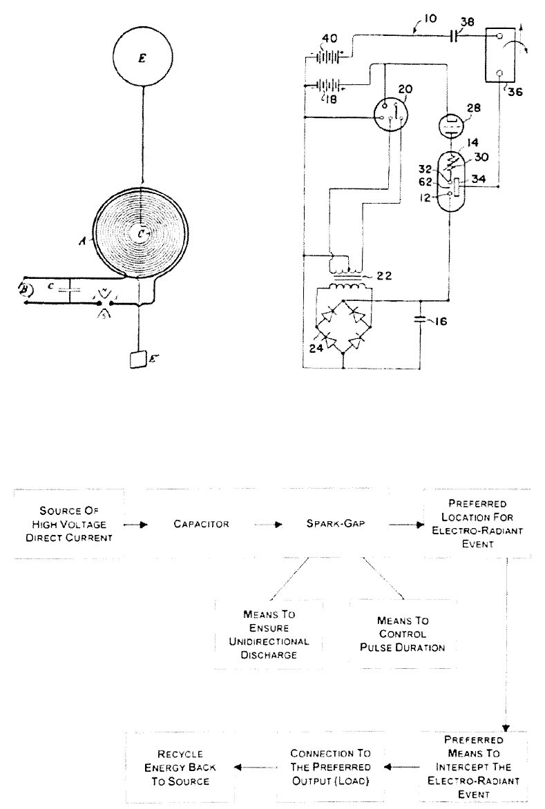
49
Decoding Gray's Patents
Common Features of Tesla's Magnifying Transmitter and Gray's Cold Electricity Circuit
Figure 27
Common Features of Tesla's Magnifying
Transmitter and Gray's Cold Electricity Circuit
50
Figure 28
Gray's Circuit “Schematic”
51
Decoding Gray's Patents
of it to actually recharge his battery, as we
read earlier. Tesla was not concerned with
this recycling process, since his system
was designed to be powered by a
hydroelectric power plant.
So it is clear from this analysis that Tesla's
Magnifying Transmitter and Gray's Cold
Electricity Circuits are, for all intents and
purposes, the same circuit. They do the same
things, in the same places, in slightly different
ways, and they both claim to produce
extremely high gains of a cold form of
"electrostatic" energy in the output. Tesla's
system was obviously much, much larger since
he was planning to power up the whole world.
Gray was only planning to power up your
home or your car. But for all intents and
purposes, these systems perform the same
functions and release the same "Electro-
Radiant" gain mechanism.
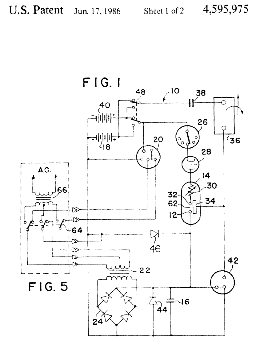
Once again, Figure 28 shows Gray's
circuit "schematic" from his "Efficient Power
Supply Suitable For Inductive Loads" patent. I
realized, after studying this diagram for a long
time, that there were a number of basic
problems with the way it was drawn. First of
all, let's look at component # 42. As this is
drawn (remember that this is a spark overshoot
device) there is a line connecting all the way
through the bottom half. If this were supposed
to be an actual electrical connection, it would
produce a short circuit, and would not allow
capacitor # 16 to charge up. So, it can clearly
be seen that this part of the drawing has
problems.
Next we will look at components # 26
and # 28 which are defined in the patent text as
follows:
Control of the conversion switching
element tube is maintained by commutator
26. A series of contacts mounted radially
about a shaft or a solid state switching
device sensitive to time or other variable
may be used for this control element. A
switching element tube type one-way energy
path, 28, is introduced between the
commutator device and the conversion
switching element tube to prevent high
energy arcing at the commutator current
path.
If the commutator, # 26, were a solid
state device, there would be no "arcing" to
prevent. Therefore, the stated purpose of # 28
in the patent text is misleading. However,
component # 28 is described as a "one-way
energy path." Gray is specifically saying that
energy in this section of the circuit can only
be allowed to move in one direction. This is
the important condition to establish, because it
is in strict compliance with the conditions
Tesla set forth in order to create the "Electro-
Radiant" event. There is also another glaring
omission in connection to component # 28.
The control grid in this triode device is not
attached to anything, and that, of course, is
what could control the timing of the spark
discharge. In the patent text, there is no
mention of how component # 28 functions
and no mention of how the grid is controlled.
Recognizing that component # 28 had no
means of being controlled was an important
realization for me.
The next problems I found were in the
inductive load, component # 36. The first is
that # 36 is described as an inductor but is not
illustrated by a coil symbol as we see with
components # 22 and # 66. Second, there are
also two odd arrows associated with this
component. The patent text implies that these
may actually be two coils that repel each other
to produce mechanical work. With this in
mind, the arrows may represent the idea of
two members deflected away from each other
in some way. This is not made clear in the
patent text. Third, we don't see any real
current path through this component, so we
don't know where the discharge goes. And
finally, fourth, the circuit comes to the second
capacitor, # 38. In the patent text this
component is described as being a part of the
recharging mechanism. However,
52
Chapter 4
none of these component connections make
any sense. For instance, if impulses coming
from the inductor, # 36, start charging up
capacitor # 38, there are no circuit
connections shown that would allow it ever to
be discharged. Therefore, because of these
omissions, I came to view this section of the
circuit more as a block diagram than as an
actual schematic.
I came to the conclusion that all that is
really apparent is that the charge receiving
grids are in relationship to the inductive load,
which is in relationship to the receiving
capacitor, which is in some relationship to the
recharging of the battery. Therefore, this
section is a block diagram, merely indicating
that these components are in relationship to
each other, rather than showing exactly how
they are wired together.
As we move towards a more complete
understanding of what Gray's schematic
diagram may actually look like, we will now
turn our attention to his "conversion element
switching tube" (Figure 29). This, finally, is
the heart of the matter, the component that
Gray always referred to as the "super secret
means of generating and mixing static
electricity." This is the element where the free
energy is generated and collected.
The conversion element switching tube is
really three components in one. It consists of
the resistor # 30, the spark gap (the space
between # 32 and # 12), and the area
surrounded by the charge-receiving grids (#
34a & # 34b). Even though it is not stated in
the patent text, we do know that the spark-gap
is rated at about 3,000 volts, based on
statements made by Gray in the newspaper
articles quoted in Chapter 1. The rear
extension of what Gray calls his "high voltage
anode" (# 12) is the surface from which the
Electro-Radiant event will be projected. This
free energy blast will radiate away from # 12,
perpendicular to the flow of current in the
path of the spark
discharge moving down that surface. The
material composition of # 12 is represented as
being relatively thick. It is not just a wire. But
what are its characteristics? The patent doesn't
describe them. We might hypothesize that this
material is a bare metal with no insulation on
it. It could possibly have a mirror finish, made
of stainless steel or a non-magnetic material.
A wide variety of options need to be tested
here, but very possibly the element's diameter
could be an important factor, as well as
whether or not it is solid or hollow. These
questions need to be explored and remain
among the only unknowns.
The concentric receiving grids (# 34a &
# 34b) around # 12 are designed to intercept
the electro-radiant event. As indicated before,
the patent states, "This element utilizes a low
voltage anode, a high voltage anode, and one
or more electrostatic or charge-receiving
grids." This drawing clearly shows two
charge-receiving grids. In the section from
Gray's patent, which refers to this component,
he says:
The shape and spacing of the electro-
static grids is also susceptible to variations
of application, voltage, current, and energy
requirements. It is the contention of the
inventor that by judicious mating of the
elements of the conversion switching
element tube and the proper selection of
the components of the circuit elements of
the system, the desired theoretical results
may be achieved. It is the inventor's
contention that this mating and selection
process is well within the capabilities of
intensive research and development
technique.
I'm sure this was his very nice way of
saying, "This is all I'm going to tell you, but
you can probably figure it out if you know
what you're doing." Then he says:
The preferred embodiment of this
invention merely assumes optimum
utilization and optimum benefit from this
invention when used with portable energy
devices similar in principle to the wet cell
or dry cell battery. This invention proposes
to