Lindemann Peter A. Секреты свободной энергии - холодное электричество
Подождите немного. Документ загружается.

3
The Edwin Gray Mystery
Figure 4
Second Article from The National Tattler
4
Chapter 1
He flicked a switch and the tiny battery sent a
charge into the capacitors. He then plugged in
six 15-watt electric light bulbs on individual
cords, a 110-volt portable television set and two
radios. The bulbs burned brightly, the
television played and both radios blared and
yet the small battery was not discharging. `You
couldn't begin to get all this current out of that
battery under ordinary circumstances,' Gray
said.
`This is the most amazing thing I've ever
seen,' exclaimed C.V. Wood, Jr., president of
the McCulloch Oil Corporation, who was also
present at the demonstration. He began looking
around for hidden outlets from the wall. `May I
prove it doesn't come from any wall plug' Gray
offered. A 40-watt light bulb screwed into an
ordinary extension socket was plugged into the
panel powered by Gray's system.
The following portion of the
demonstration is shown in the photograph in
Figure 3:
The bulb lit, then Gray dropped it into
a cylinder filled with water. `What would
be happening if this was getting ordinary
power right now?' Gray asked, as he stuck
his hand in the water with the glowing light
bulb. `You'd be electrocuted and that thing
would be popping and sputtering until the
then put his finger into the water with the
light. No shock. `Gentlemen, this is a new
manifestation of electricity,' Hackenberger
said.
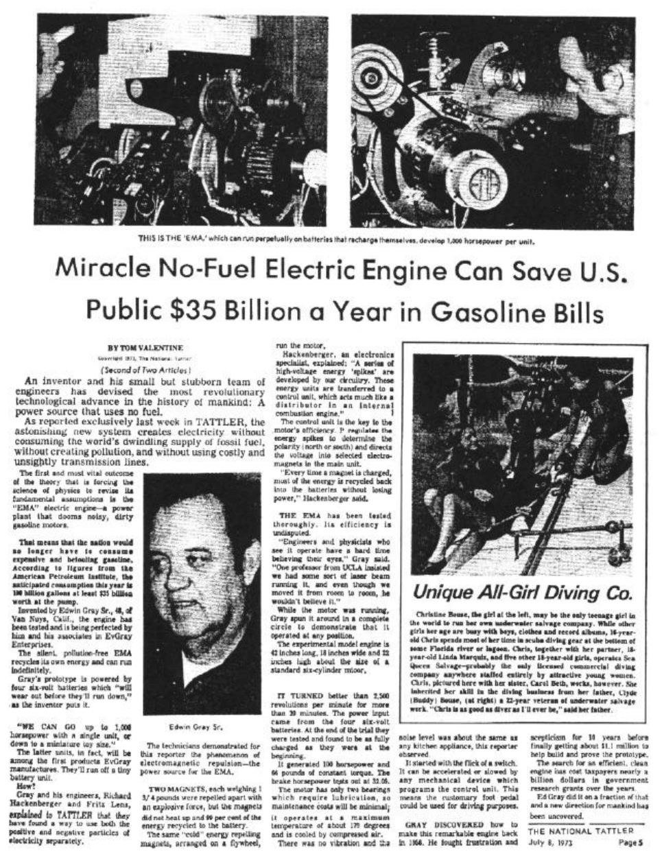
flywheel, run the motor. Hackenberger, an
electronics specialist explained, `A series of
high-voltage energy spikes are developed
in our circuitry. These energy units are
transferred to a control unit which acts
much like a distributor in an internal
combustion engine. Every time a magnet is
charged, most of the energy is recycled
back into the batteries without losing
power.
Figure 5
Article from Probe The Unknown
Well, this was quite literally the most
amazing thing I had ever read in a newspaper.
I was completely hooked. The
next week I picked up the second article in the
series, titled "Miracle No Fuel Electric Engine
Can Save Public $35 Billion A Year In
Gasoline Bills" (Figure 4). It centered on an
amazing new type of electric motor that ran
on Gray's system:
The silent pollution-free EMA motor
recycles its own energy and can run
indefinitely. Gray's prototype is powered by
four 6-volt batteries which `will wear out
before they'll run down.' The same `cold'
energy repelling magnets, arranged on a
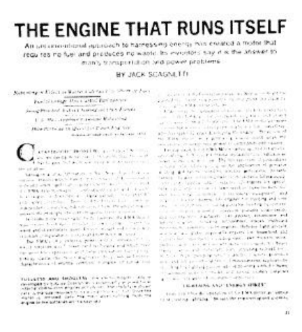
Around that same time, there appeared
another article in a magazine called Probe The
Unknown authored by Jack Scagnetti called
"The Engine That Runs Itself." (Figure 5) He
presented very similar information as that
contained in the articles by Tom Valentine.
Gray describes the operation of his EMA
motor as similar to recreating lightning:
Richard Hackenberger, Vice President
in Engineering for EVGray, explains how
the EMA motor system operates. `Power
from the high voltage section is put through
a system of electrical circuitry to produce a
5
The Edwin Gray Mystery
Figure 6
Letter from EVGray Enterprises
6
Chapter 1
series of high voltage energy spikes. The spikes
are transferred to a control unit, which in turn
operates the major motor unit'. `While this
occurs, the recycle/ regeneration system is
recharging the battery with 60 to 120 amp
pulses.'
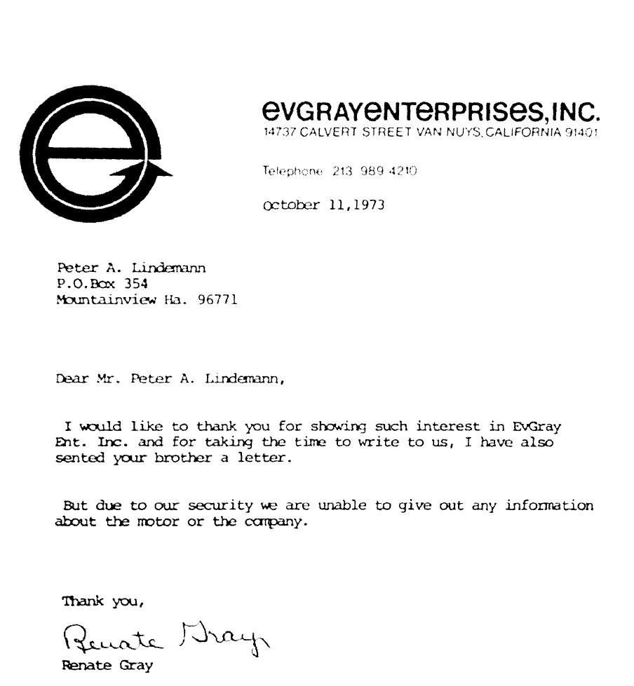
These several newspaper articles totally
captivated my imagination. Shortly afterwards, my
brother and I wrote to EVGray Enterprises in Van
Nuys, California expressing our interest and desire
to have more information. I received the following
letter from them in October, 1973: "Dear Mr.
Lindemann: I would like to thank you for
showing such interest in EVGray Enterprises,
Inc. and for taking the time to write us. I have
also sent your brother a letter. But due to our
security, we are unable to give out any
information about the motor or the Company."
(Figure 6) Needless to say, this was extremely
disappointing. So, reluctantly, I put the Valentine
and Scagnetti articles and the
Figure 7
Cover of NewsReal Magazine
letter from EVGray away in a file, which
eventually grew into my very extensive
research on the subject of "Free Energy."
Unfortunately, I didn't read any more
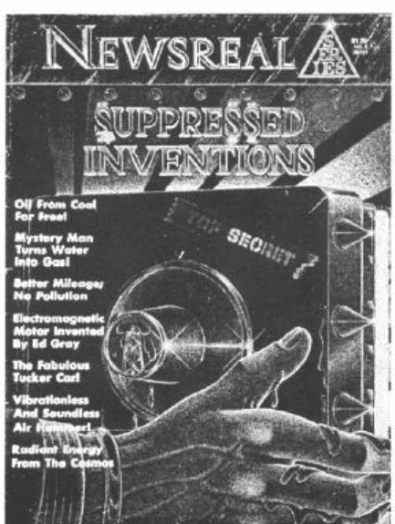
about Ed Gray for the next couple of years. In
1977, however, I came across another article by
Tom Valentine in an issue of a magazine called
NewsReal (Figure 7) devoted to suppressed
inventions. Valentine wrote about a wide
variety of subjects ranging from making oil
from coal, to making gasoline from water, to
airplanes that won't stall, and other amazing
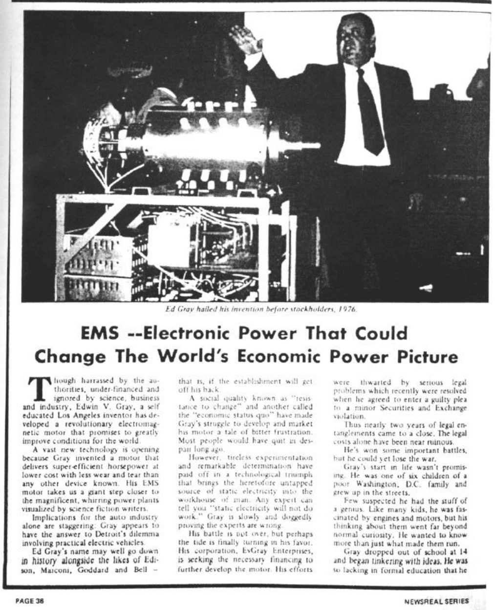
inventions. Included was an update on Edwin
Gray entitled, "EMS - Electronic Power That
Could Change The World's Economic Power
Picture." (Figure 8)
In this article, Ed Gray says:
`I remember getting a shock when I
grabbed a charged capacitor off a
workbench. That simple fact never left my
mind. Then I watched when the government
people were testing the first radar across the
Potomac River. It stuck in my mind when
one of the men explained it as `pulse out,
pulse back'. And I've always been a nut
about thunderstorms. I watched lightning by
the hours. I noticed how much stronger it
appeared to be when closer to the earth, and
just naturally concluded that the more air
had something to do with it. These three
principles, plus a super secret means of
generating and mixing static electricity,
make up Gray's EMS motor.'
Later in the article:
`There is no motor like this in the world' Dr.
Chalfin told the group. `Ordinary electric
motors use continuous current and
constantly drain power. In this system,
energy is used only during a small fraction
of a millisecond. Energy not used is returned
to an accessory battery for reuse.' `It is cool
running,' Dr. Chalfin added, putting his
hand on the motor. `There is no loss of
energy in the system.'
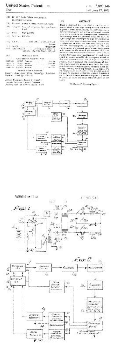
Gray's first patent, issued in June of 1975,
was titled "Pulsed Capacitor Discharge Electric
Engine." (Figure 9) I
7
Figure 8
Article from NewsReal Magazine
The Edwin Gray Mystery
8
Chapter 1
Figure 9
Gray's Motor Patent Cover Sheet
Figure 10
Gray's Motor Patent Schematic
received a copy of it in 1978. It is a rather
extensive patent with 18 pages, 19
illustrations, and 18 claims. It describes an
engine that is run by discharging capacitors
through electromagnets that oppose each
other. (Figure 10)
But I discovered soon enough that if you
try to build this motor according to the
principles outlined in this patent, it doesn't
perform anything like what was described in
the Valentine articles. In fact, it doesn't
produce a cold form of electricity at all. If
you happened to get into the discharge path
of those capacitors, you'd be thrown clear
across the room. What's more, the amount of
energy that could be recycled from this
arrangement is negligible compared to what
Gray is talking about in those articles. It
became quite obvious to me, that in spite of
the fact that this patent protected the specific
design of the motor, it did not reveal the
technique of its operation.
From the beginning, I was always more
interested in the solid-state circuit. I realized
that the production of cold electricity really
had nothing to do with the motor and that
the motor was a secondary event. After all,
when Gray was popping the magnets with
cold electricity and running the TV and the
light bulbs on cold electricity, he didn't need
the motor. Intuitively, I knew from the outset
that the key to unraveling the secret of Gray's
discovery lay in an attempt to completely
understand his solid-state circuit. However,
the resources I had gathered thus far were
inadequate at best, and by the late 70's, I had
pretty much exhausted all the information
that was available on this subject.
During the late 1980's, I only heard
rumors that Gray was continuing his work,
but all I could really determine was that no
more news articles, or anything else for that
matter, ever appeared about him.
9
The Edwin Gray Mystery
In the mid-1990's, however, a research
associate of mine told me that he had heard
that Gray had been issued other patents and
this completely intrigued me. Would these
new patents contain the answers I was
looking for? I didn't know for sure, but I
knew I needed to get hold of these
documents. Unfortunately, my associate
didn't have them, and he didn't know what
the patent numbers were. So once again, my
search for Ed Gray's "cold electricity" came
to a dead end, at least for a few more years.
In June of 1999, while visiting the IBM
Intellectual Property Network on the internet
(now the Delphion Intellectual Property
Network), I noticed that the search engines
within the patent database had been recently
updated so it was now possible to restrict a
search just to the Inventor Line. "Gray" into a
search and looked at every word in every
patent from 1971 forward, you got so many
hits you couldn't possibly go through them
all. Now, however, I was able to plug "Gray;
Edwin" into the Inventor Line of this newly
updated search engine. Lo and behold, on my
screen 30 seconds later, the numbers of two
other patents that had been issued to Edwin
Gray came up. I was ecstatic!
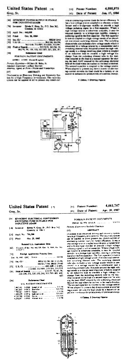
Figure 11 shows the first of these patents
entitled "Efficient Power Supply Suitable for
Inductive Loads" issued in June 1986.
Understanding this patent will be the primary
focus of this book.
The other patent entitled "Efficient
Electrical Conversion Switching Tube
Suitable for Inductive Loads" (Figure 12)
was issued approximately ten months later,
in April 1987.
These two patents are very closely
linked and are almost identical. One of them
describes the circuit that drives this switching
tube and the other one describes the
switching tube itself. About 80% of
Figure 11
Gray's Circuit Patent Cover Sheet
Figure 12
Gray's Conversion Tube Patent Cover Sheet
10
Chapter 1
Figure 13
Gray's Circuit "Schematic"
11
The Edwin Gray Mystery
the wording in both of these patents is
identical.
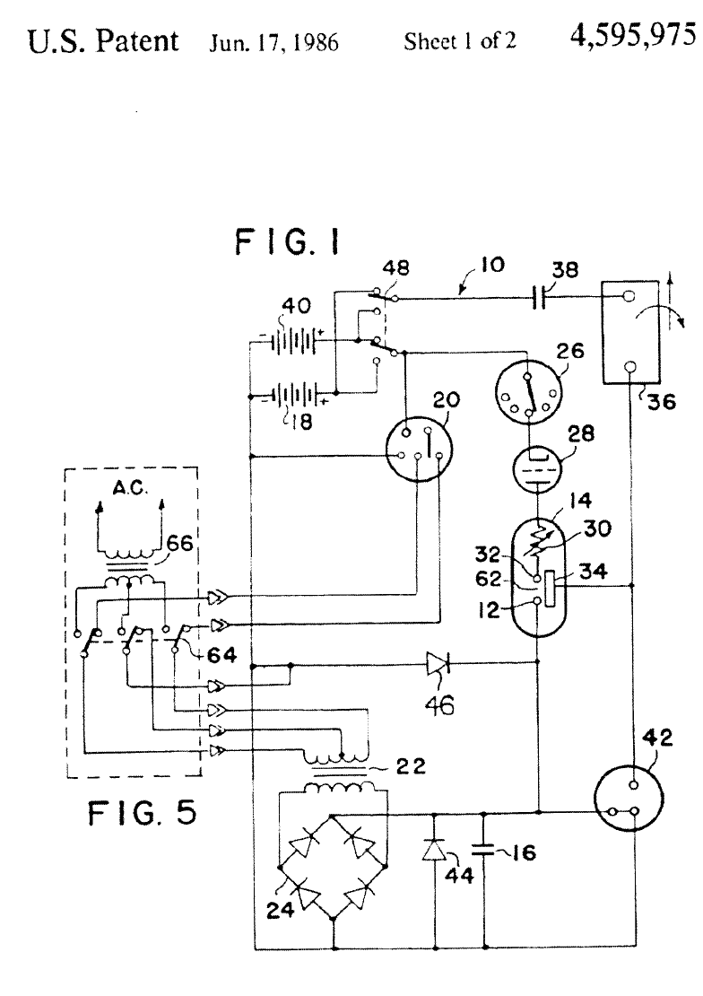
Figure 13 shows the circuit diagram for
the first one. I had searched 26 years for this
diagram, and finally I had a chance to
understand what Gray was doing. I felt sure
that I was looking at the basis of his "cold"
electricity circuits, but Gray was still holding
his cards quite close to his chest. Reading the
diagram, it was not clear how these
components behaved, or what they did, or
why. The more I studied the text, which is
relatively short compared to the motor patent,
the more I realized I was looking at something
that was really quite foreign to me.
Intuitively, I felt I had all the pieces, but I still
didn't know how the pieces fit together, and I
didn't know what the true picture looked like.
Why was this circuit able to create free
energy? Once again, there were still far too
many unknowns.
I was heartened, though, by several
interesting references stated in the patent.
For instance, in one small section, Gray
states:
There is disclosed herein an electrical
driving system which, on theory, will
convert low-voltage electrical energy from
a source, such as an electric storage
battery, to a high-potential, high-current
energy pulse that is capable of developing
a work force at the inductive output of the
device that is more efficient than that
which is capable of being developed
directly from the energy source.
That statement may sound a bit obscure,
but actually as far as I was concerned, it was
a pretty sneaky way of saying "free energy."
Further on it says:
This system accomplishes the results
stated above by harnessing the 'electro-
static' or `impulse' energy created by a
high intensity spark generated within a
specially constructed electrical conversion
switching element tube. This element
utilizes a low voltage anode, a high voltage
anode, and one or more electro-static or
charge receiving grids. These grids are of a
physical size, and appropriately
positioned, as to be compatible with the
size of the tube, and therefore, directly
related to the amount of energy to be
anticipated when the device is operating
As I continued to read this patent, I was
most intrigued by components # 42, # 44,
and # 46. The patent states:
A spark-gap protection device, 42, is
included in the circuit to protect the
inductive load and the rectifier elements
from unduly large discharge currents.
Should the potentials within the circuit
exceed predetermined values, fixed by the
mechanical size and spacing of the
elements within the protected device, the
excess energy is dissipated (bypassed) by
the protective device to the circuit
common (electrical ground)..." diodes 44
and 46 bypass the excess overshoot
generated when the energy conversion
switching element tube is triggered.
So here we have three elements, # 42, #
44 and # 46 in this circuit, which are
specifically designed to dump excess energy
when this tube fires! What this suggests is
that there is the possibility of producing so
much energy here that it can damage the
rest of the circuit. Certainly this was quite
promising, but I still didn't really understand
what phenomenon would create those
conditions -- or why. It was definitely
apparent to me, however, that Gray expected
something extremely "large" to happen when
this conversion switching tube fired.
I was convinced I had discovered the
secret of the device, but I still didn't really
understand what I was looking at. I needed
a "Rosetta Stone" -- something that would
translate all of these unknowns into an
understandable context.
Luckily, I found it. That Rosetta Stone
was a book called Secrets 6f Cold War
Technology: Project HAARP and Beyond,
written by Gerry Vassilatos in 1996 and
currently available through Adventures
Unlimited Press (Figure 14). In Chapter 1,
12
titled "Nikola Tesla and Radiant Energy,"
Vassilatos recounts those heady days back
around 1890, when Nikola Tesla is developing
the experiments which led to the invention of his
magnifying transmitter. It is an astonishing work,
and I highly recommend that you acquire and
read the entire publication. However, for the
purposes of this book, the following excerpted
sections from Chapter I will reveal not only a
fascinating story of discovery, but, more
importantly, will provide the foundation for full
comprehension of Tesla's amazing magnifying
transmitter and, subsequently, its connection to
Edwin Gray's "cold electricity" circuit.
Figure 14
Secrets of Cold War Technology:
Project HAARP and Beyond