Lee K.K. Lectures on Dynamical Systems, Structural Stability and Their Applications
Подождите немного. Документ загружается.

and
in
the
sensory
systems.
Recurrent
feedback
occurs
when
activity
in
a
population
of
neurons
excites,
via
axon
collaterals,
a
second
population,
which
in
turn
excites
or
inhibits
the
first.
Models
that
include
recurrent
feedback
fall
into
two
main
categories.
The
first
consists
of
models
of
a
specific
part
of
the
nervous
system
where
recurrent
feedback
is
important,
while
the
models
in
the
second
category
are
developed
specifically
to
describe
resurrent
feedback
without
reference
to
a
particular
part
of
nerve
system.
Nonetheless,
both
types
include
time
delays
due
to
the
conduction
times
and
synaptic
delays
in
the
feedback
circuit.
The
model
of
Mackey
and
an
der
Heiden
(1984]
incorporates
the
stoichiometry
of
synaptic
transmitter-
receptor
interactions
and
time
delays
and
leads
to
a
nonlinear
term
for
recurrent
feedback.
An
even
simpler
model
for
recurrent
feedback
is
that
of
Plant
[1981],
which
is
a
modification
of
the
FitzHugh-Nagumo
equations
for
a
nerve
cell
(FitzHugh
1961]
emphasizes
the
behavior
of
an
individual
cell
membrance.
Recently,
Castelfranco
and
Stech
(1987]
provide
a
more
comprehensive
understanding
of
the
structure
of
periodic
orbits
in
Plant's
model
and
viewed
the
system
as
a
two-parameter
Hopf
bifurcation
problem
associated
with
delayed
feedback
in
the
FitzHugh
model.
Ikeda
et
al
(1982]
have
studied
delayed
feedback
systems
in
detail
and
they
have
found
that
higher-harmonic
oscillating
states
apear
successively
in
the
transition
to
chaos.
It
has
been
pointed
out
that
the
first
order
transitions
between
these
states
account
for
the
frequency-
locked
anomaly
observed
by
Hopf
et
al
(1982]
in
a
hybrid
optical
bistable
device.
An
inverse
Liapunov
problem
was
studied
by
Liu
and
Leake
[1967].
They
studied
the
controllable
dynamical
system
of
Eq.(7.7-1)
and
established
means
to
determine
the
system
function
for
the
control
function
u
so
that
Eq.(7.7-1)
behaves
in
an
"acceptable"
manner
such
as
uniform
asymptotic
stability
in
the
whole
(u.a.s.w.),
which
is
equivalent
to
asymptotic
stability
in
the
whole
if
the
function
f
is
384
autonomous
or
f
is
periodic
in
t,
and
equivalent
to
asymptotic
stability
if,
f
is
also
linear.
Indeed,
such
stability
is
probably
the
most
desirable
type
of
stability
for
practical
systems.
They
have
shown
the
following
theorem:
Theorem
7.7.3
Let
f e C
0
(local
Lipschitz
condition)
and
let
x = 0
be
the
equilibrium
is
u.a.s.w.
iff
there
exists
a
scalar
function
V(x,t)
such
that:
(i)
V(x,t)
is
of
class
C
1
,
positive
definite,
decrescent,
and
radially
unbounded;
and
(ii)
whose
Eulerian
derivative
dV(x,t)jdt
is
negative
definite.
Here
the
Eulerian
derivative
is
defined
by
dV/dt
<f,
grad
V>
+
Vt,
where
<>
denotes
the
inner
product,
Vt
av;at,
and
grad
v
the
gradient
of
v.
Unfortunately,
there
are
no
general
means
available
whereby
one
can
actually
find
v.
The
inverse
problem
is
that,
given
a
pair
of
scalar
functions
V(x,t)
and
dV(x,t)/dt,
one
must
find
the
function
f
(or
u)
so
that
the
Eulerian
derivative
is
satisfied.
The
solution
of
the
inverse
problem
together
with
the
known
results
of
Liapunov's
direct
method
can
be
applied
directly
to
the
synthesis
(or
design)
of
nonlinear
control
systems.
They
also
have
to
find
the
necessary
and
sufficient
conditions
for
multi-
loop
feedback
control
systems
and
their
complete
asymptotic
controllability
conditions.
For
the
feedback
system
of
dxjdt
=Ax+
bf(cx),
a
very
interesting
stability
criterion
for
the
asymptotic
stability
in
the
large
is
the
Popov
criterion
[Popov
1962].
In
a
different
vein,
Westcott
[1986]
gave
a
brief
review
of
the
application
of
feedback
control
theory
to
macro-economic
models.
7.8
Semiconductor
laser
linewidth
reduction
by
feedback
control
and
phased
arrays
A
narrow-linewidth,
frequency
stablized
laser
is
a
very
useful
device
in
many
aspects
of
pure
and
applied
research
385
such
as
spectroscopy,
laser
communication,
lidar
and
remote
sensing,
heterodyne
detection,
etc.
Unlike
conventional
lasers,
the
field
power
spectra
of
semiconductor
lasers
are
not
dominated
by
mechanical
cavity
fluctuations,
but
instead,
external
noise
sources
such
as
ambient
temperature
fluctuations,
injection
current
fluctuations
due
to
the
noises
from
a
power
supply,
and
so
on,
in
addition
to
the
spontaneous
emission,
contribute
to
the
linewidth.
Electrical
or
optical
feedback
techniques
have
been
very
successful
in
reducing
linewidth
significantly.
Simple
electrooptic
feedback
systems
have
been
utilized
for
diode
lasers
to
correct
for
amplitude
andjor
frequency
fluctuations
due
to
variations
in
drive
current
and
ambient
temperature.
For
a
recent
review
of
frequency
stable
semiconductor
lasers,
see,
e.g.,
Lee
and
Chen
[1990].
Simultaneous
intensity
and
frequency
stabilization
can
be
achieved
by
detecting
the
fluctuations
in
these
characteristics
and
to
control
both
the
diode
operating
temperature
and
drive
current
[Yamaguchi
and
Suzuki
1983].
One may
have
noticed
that
the
huge
difference,
over
nine
orders
of
magnitude
between
the
limiting
linewidth
and
the
cavity
linewidth
for
conventional
gas
or
semiconductor
lasers,
is
mainly
due
to
the
very
short
photon
lifetime,
tc,
which
is
proportional
to
~u%_,
in
the
resonantors.
Clearly,
to
increase
tc,
i.e.,
decrease
the
linewidth,
in
particular
for
semiconductor
lasers,
is
to
increase
the
cavity
length
L
by
placing
the
laser
in
an
external
resonator
and
by
using
high
reflectance
mirrors.
Indeed,
semiconductor
laser
linewidths
in
kHz
regime
in
an
external
cavity
have
been
demonstrated
[Shay
1987].
There
are
several
papers
which
provide
simplified
analytical
discussions
of
external
cavities
with
some
restrictions
[Fleming
and
Mooradian
1981,
Henry,
1986].
These
analyses
can
provide
guidelines
as
to
the
amount
of
linewidth
reduction
which
can
be
realized
with
external
cavity.
It
should
be
pointed
out
that
rigorous
analyses
of
386
the
external
cavity
of
a
diode
laser
are
quite
complex
and
not
thoroughly
understood.
It
is
known
that
the
spectral
behavior
is
strongly
dependent
on
the
level
of
optical
feedback
[Patzak
et
al
198Ja,b,
Lenstra
et
al
1985,
Tkach
and
Chraplyvy
1985,
Henry
and
Kazarinov
1986,
Henry
1986]
and
the
phase
relationship
between
the
diode
field
and
the
feedback
field
[Chen
1984].
As
in
injection
locking,
in
general,
the
higher
the
feedback
amount
is,
the
greater
the
linewidth
reduction
can
be
achieved.
Nonetheless,
it
should
be
cautioned
that
at
a
varying
feedback
level
at
a
certain
high
level
of
feedback,
the
linewidth
reduction
tends
to
saturate,
and
is
then
followed
by
an
abrupt
increase
in
linewidth
by
several
orders
of
magnitude.
This
effect
was
observed
for
instance
by
Goldberg
et
al
[1982]
and
Favre
et
al
[1982].
It
has
been
pointed
out
that
both
the
saturation
phenomenon
and
the
sudden
increase
in
linewidth
are
consequences
of
the
nonlinear
dynamics,
for
instance,
[Olesen
et
al
1986,
Otsuka
and
Kawaguchi
1984].
As
has
been
pointed
out
by
Lenstra
et
al
[1985],
the
state
of
increased
linewidth
has
the
distinct
signature
of
a
chaotic
attractor.
Indeed,
the
coherence
collapse
is
due
to
optical
delay
feedback
[Dente
et
al
1989].
Due
to
their
high
gains,
semiconductor
lasers
are
very
sensitive
to
feedbacks.
Feedback
not
only
induces
phase
(i.e.,
frequency)
fluctuations,
but
also
induces
amplitude
fluctuations,
and
may
eventually
lead
to
chaos.
Very
recently,
Li
and
Abraham
[1989]
have
shown
that
the
semiconductor
laser
with
optical
feedback
functions
as
a
laser
with
an
optical
servoloop
can
be
considered
a
self-injection
locking
laser,
and
they
also
determine
the
effect
of
various
parameters
on
the
noise
reduction
and
on
the
stability
of
single-
mode
operation
of
the
laser.
In
order
to
achieve
high
power,
semiconductor
lasers
have
to
be
phase
locked
together
to
form
a
phased
array.
Such
phase
locked
semiconductor
phased
arrays
have
been
demonstrated
[Teneya
et
al
1985,
Hohimer
1986,
Leger
et
al
1988,
Carlson
et
al,
1988].
Earlier
studies
of
semiconductor
387
phased
arrays
are
mainly
focused
on
their
spatial
mode
structures
under
steady
state
operating
conditions.
These
spatial
mode
patterns
in
terms
of
supermodes
are
observed
and
well
understood
[Scifres
et
al
1979,
Botez
1985,
Butlet
et
al
1984,
Peoli
et
al
1984].
Nonetheless,
little
has
been
said
about
the
temporal
or
time
evolutionary
behavior
of
such
phase
locked
semiconductor
arrays.
Only
very
recently,
there
have
been
a
few
papers
concerning
the
dynamical
behavior
of
the
phased
arrays
[Elliott
et
al
1985,
Wang
and
Winful
1988].
What
we
would
like
to
know
are:
(a)
under
what
operating
conditions
will
the
semiconductor
laser
array
be
phase
locked,
(b)
how
long
will
it
take
for
locking
to
take
place,
(c)
will
the
locking
be
stable,
i.e.,
be
persistent
for
a
very
long
time,
(d)
if
it
can
only
be
locked
for
a
"short"
time,
then
what
happens
after
they
become
unlocked,
(e)
what
are
the
details
and
routes
to
instabilities,
(f)
can
we
classify
the
various
routes
to
instabilities
from
the
variations
of
various
operating
parameters,
(g)
and
above
all,
with
reasonable
operating
conditions,
can
one
prove
a
general
statement
concerning
the
existence
or
non-existence
of
a
stable
region
for
a
semiconductor
laser
array.
There
are
many
ways
to
initiate
the
phase
locking
of
the
semiconductor
phased
array.
One
way
is
the
injection
locking,
which
has
been
demonstrated
for
gain
guided
semiconductor
laser
array
[Hohimer
et
al
1986].
But
for
index
guided
laser
array,
some
phase
shifters
may
be
necessary
for
phase
locking.
Another
method
for
phase
locking
is
using
a common
external
cavity
for
the
laser
array,
whereby
the
phase
locking
is
accomplished
by
mutual
feedback,
i.e.,
self-organization.
Of
course,
in
order
to
increase
the
amount
of
mutual
feedback,
the
self-imaging
technique
can
be
employed
[Leger
et
al
1988].
Here
we
shall
not
debate
the
relative
merit
of
either
method,
or
other
generic
methods,
it
suffices
to
say
that
in
the
following
formulations
and
discussion,
the
general
conclusion
will
be
the
same.
Even
though
we
shall
only
discuss
the
formulation
of
an
semiconductor
laser
array
undergoing
mutual
feedback,
388
the
case
of
injection
locking
can
be
modified
trivially
as
we
shall
indicate.
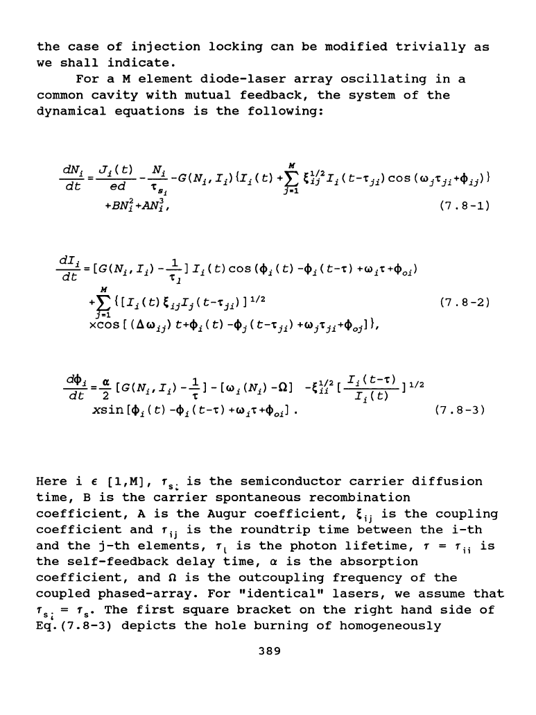
For
a M
element
diode-laser
array
oscillating
in
a
common
cavity
with
mutual
feedback,
the
system
of
the
dynamical
equations
is
the
following:
dcj>.i
=~
[G(N.,
I.)_.,!]
-[c.>.
(N.)
-0]
3l:~
2
[
I.i
(
t--r)
]1/2
dt
2 ' '
-r
' '
'ou
I
1
(
t)
xsin
[cj)i
(
t)
-cl>i (
t--r)
+c..>i-r
+cj>
0
i]
•
(7
•
8-3)
Here
i e
[l,M],
f
8
•
is
the
semiconductor
carrier
diffusion
time,
B
is
the
carrier
spontaneous
recombination
coefficient,
A
is
the
Augur
coefficient,
~ii
is
the
coupling
coefficient
and
T
ii
is
the
roundtrip
time
between
the
i-th
and
the
j-th
elements,
r
1
is
the
photon
lifetime,
T =
T;;
is
the
self-feedback
delay
time,
a
is
the
absorption
coefficient,
and
n
is
the
outcoupling
frequency
of
the
coupled
phased-array.
For
"identical"
lasers,
we
assume
that
T
8
•
= T
8
•
The
first
square
bracket
on
the
right
hand
side
of
' .
Eq.(7.8-3)
dep1cts
the
hole
burning
of
homogeneously
389
the
laser
frequencies
~;(N;)
depend
on
the
carrier
density
by
(7.8-4)
(7.8-5)
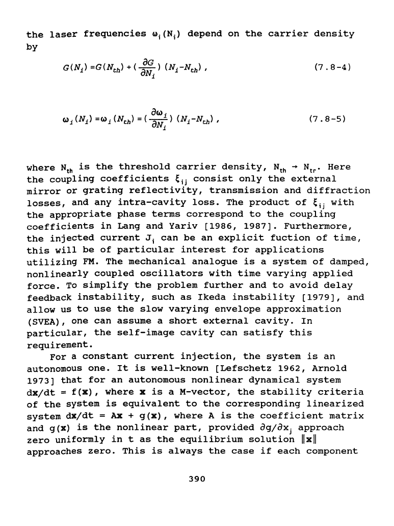
where
Nth
is
the
threshold
carrier
density,
Nth
-+
Ntr•
Here
the
coupling
coefficients
~ii
consist
only
the
external
mirror
or
grating
reflectivity,
transmission
and
diffraction
losses,
and
any
intra-cavity
loss.
The
product
of
~ii
with
the
appropriate
phase
terms
correspond
to
the
coupling
coefficients
in
Lang
and
Yariv
[1986,
1987].
Furthermore,
the
injected
current
J;
can
be
an
explicit
fuction
of
time,
this
will
be
of
particular
interest
for
applications
utilizing
FM.
The
mechanical
analogue
is
a
system
of
damped,
nonlinearly
coupled
oscillators
with
time
varying
applied
force.
To
simplify
the
problem
further
and
to
avoid
delay
feedback
instability,
such
as
Ikeda
instability
[1979],
and
allow
us
to
use
the
slow
varying
envelope
approximation
(SVEA),
one
can
assume
a
short
external
cavity.
In
particular,
the
self-image
cavity
can
satisfy
this
requirement.
For
a
constant
current
injection,
the
system
is
an
autonomous
one.
It
is
well-known
[Lefschetz
1962,
Arnold
1973]
that
for
an
autonomous
nonlinear
dynamical
system
dxjdt
=
f(x),
where
xis
aM-vector,
the
stability
criteria
of
the
system
is
equivalent
to
the
corresponding
linearized
system
dX/dt
=Ax+
g(x),
where
A
is
the
coefficient
matrix
and
g(X)
is
the
nonlinear
part,
provided
agjaxj
approach
zero
uniformly
in
t
as
the
equilibrium
solution
llxll
approaches
zero.
This
is
always
the
case
if
each
component
390
of
g(x)
is
a
polymonial
in
X;
which
begins
with
terms
of
order
2
or
higher.
Put
it
differently,
if
each
component
of
g(x)
is
differentiable,
it
will
also
satisfy
the
condition.
It
is
also
well-established
that
the
linearized
system
is
stable
if
all
the
eigenvalues
of
the
system
is
negative,
or
the
real
part
of
the
eigenvalues
be
negative.
From
these
established
results,
we
have
the
following
algorithm
for
determining
the
stability
region
of
the
coupled
semiconductor
phased
array.
We
first
transform
the
coupled
dynamical
system
into
standard
form,
i.e.,
first
find
the
equilibrium
(steady
state)
solutions
and
transform
the
origin
to
the
equilibrium
points
by
setting
z = x - X
0
•
We
then
linearize
the
system
and
write
f(x
0
+
z)
in
the
form
Az
+
g(z)
where
A
is
the
linear
part
of
f(x
0
+
z).
We
then
compute
the
eigenvalues
of
the
linearized
system,
i.e.,
A.
By
varying
all
the
operating
parameters
of
the
system,
and
finding
the
values
where
all
the
eigenvalues
are
negative,
one
can
then
"map"
out
the
stability
region
of
the
system.
Clearly,
the
system,
Eqs.(7.8-1-3),
is
very
complex
and
nearly
intractable
even
numerically.
Nonetheless,
we
shall
discuss
its
qualitative
properties
in
a
series
of
full
length
papers
eleswhere.
The
most
simple
case
which
still
preserves
both
the
self-feedback
and
cross-feedback
is
the
coupling
of
two
semiconductor
lasers
in
an
external
cavity.
As
we
have
just
mentioned,
in
order
to
avoid
delay
feedback
instability,
and
allow
us
to
use
SVEA,
we
assume
a
short
external
cavity,
such
that
r < r
5
•
The
typical
carrier
diffusion
time
is
of
the
order
of
1
nsec,
then
the
external
cavity
length
is
assumed
to
be
2 em.
Thus
we
have
r
12
= r
21
=
r
11
= r
22
=
r.
From
SVEA,
we
have
I;(t-
r)
=
I;(t).
Furthermore,
from
the
symmetry
of
~ii
we
have,
~
12
=
~
21
=
K.
We
than
have
the
following
set
of
six
first
order
nonlinearly
coupled
ordinary
differential
equations.
Notice
the
symmetry
between
1
and
2,
in
later
discussions
this
symmetry
should
be
kept
in
mind.
dN
1
/dt
=
Jjed
- N
1
/T
5
-
G[I
1
(t)
+
KV.
I
2
(t
-
T)
391
dN
2
/dt
Jjed
- N
2
/f
8
-
G[I
2
(t)
+
K~
I
1
(t
-
f)
•
cos(w
1
f +
1/>
01
)]
+
BN
2
2
+
AN
2
3
,
di
1
jdt
(G
-
1jf
1
]
I
1
(t)
+
KYr[I
1
(t)
I
2
(t
-
f)
]Yr
•
cos(q,
1
(t)
-
q,
2
(t
-
f)
+ w
2
f +
l/lo2l,
di
2
/dt
(G-
1/f
1
]I
2
(t)
+
KYr[I
2
(t)I
1
(t-
f)]Yr
•
cos(q,
2
(t)
-
q,
1
(t
-
f)
+ w
1
f +
1/>
0
,],
dq,,;dt
a(G
-
1/f
]/2
-
(w
1
(N
1
)
-
w]
-
KYr(I
1
(t
-
•
sin(q,
1
(t)
-
1/>
1
(t
-
1)
+ w
1
f
+ 1Po1] '
dl/>2/dt
a(G
-
1/f]/2
-
(w2(N2)
-
w]
-
KYr(I
2
(t
-
•
sin
(q,
2
(t)
-
1/>2
(t
-
f)
+
(a)2f
+ lj)o2],
(7.8-6a)
(7.8-6b)
(7.8-6c)
(7.8-6d)
f)/I
1
(t)]Yr
(7.8-6e)
f)/I
2
(t)
]Yr
(7.8-6e)
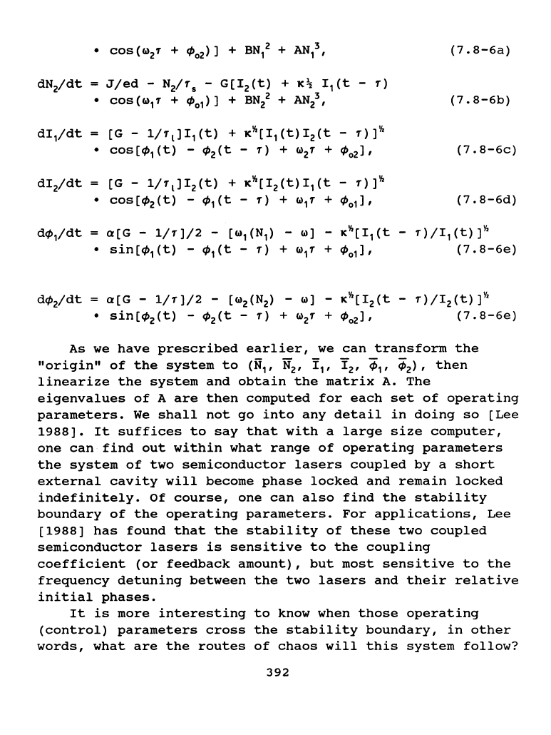
As
we
have
prescribed
earlier,
we
can
transform
the
"origin"
of
the
system
to
(N
1
,
'N
2
,
!
1
,
Y
2
,
¢
1
,
¢
2
>,
then
linearize
the
system
and
obtain
the
matrix
A.
The
eigenvalues
of
A
are
then
computed
for
each
set
of
operating
parameters.
We
shall
not
go
into
any
detail
in
doing
so
(Lee
1988].
It
suffices
to
say
that
with
a
large
size
computer,
one
can
find
out
within
what
range
of
operating
parameters
the
system
of
two
semiconductor
lasers
coupled
by
a
short
external
cavity
will
become
phase
locked
and
remain
locked
indefinitely.
Of
course,
one
can
also
find
the
stability
boundary
of
the
operating
parameters.
For
applications,
Lee
(1988]
has
found
that
the
stability
of
these
two
coupled
semiconductor
lasers
is
sensitive
to
the
coupling
coefficient
(or
feedback
amount),
but
most
sensitive
to
the
frequency
detuning
between
the
two
lasers
and
their
relative
initial
phases.
It
is
more
interesting
to
know when
those
operating
(control)
parameters
cross
the
stability
boundary,
in
other
words,
what
are
the
routes
of
chaos
will
this
system
follow?
392
There
have
been
many
experimental
attempts
to
map
out
the
dynamics
of
this
"simple"
system,
yet
none
have
been
successful.
The
reason
is
that
the
detectors
and
oscilloscopes
are
too
slow
(usually
of
the
order
of
one
nanosecond)
while
the
coupling
of
two
diodes
is
taking
place
at
about
30
- 50
psec.
Thus,
the
oscilloscope
displays
a
big
blob
of
hundreds
of
return
maps.
Certainly,
this
situation
is
not
satisfactory
to
say
the
least.
Another
approach
is
to
use
a
streak
camera
[Elliott
1985].
But
that
is
not
satisfactory
either
due
to
the
fact
that
it
can
not
take
sufficient
samples
for
a
short
time
span,
i.e.,
to
map
out
the
time
evolution
of
the
dynamics.
Consequently,
one
has
to
find
some way
to
overcome
the
difficulty
posed
by
the
fast
coupling
of
diode
lasers.
We
would
like
to
point
out
from
Eqs.(7.8-6)
that
if
the
two
coupled
diode
lasers
are
operated
at
small
signal
gain
regime,
i.e.,
G(N;)
=aN;+
b,
where
a
and
bare
constants,
the
only
nonlinear
coupling
terms
between
N;
and
E;
(here
i
=
1,2)
are
of
the
form
of
direct
product.
In
this
case,
the
phase
space
of
this
system
is
a
product
space.
In
other
words,
the
phase
space
of
this
system
can
be
decomposed
into
two
"orthogonal"
subspaces,
the
recombination
rate
subspace,
N
1
and
N
2
,
a
two-dimensional
subspace,
and
the
subspace
of
amplitudes
and
phases
of
the
two
lasers,
a
four-dimensional
subspace.
Due
to
the
product
nature
of
the
phase
space,
one
can
determine
the
dynamics
of
the
system
both
experimentally
and
theoretically
by
studying
its
two
orthogonal
subspaces.
Simply
put,
it
is
analogous
to
the
understanding
of
the
helical
motion
of
an
electron
under
the
influence
of
a
constant
magnetic
field.
It
is
the
product
of
the
circular
motion
of
an
electron
under
a
constant
magnetic
field,
and
the
motion
of
the
electron
along
z-axis.
The
composite
motion
is
the
product
action.
The
trajectories
"projected"
on
the
(N
1
,N
2
)-subspace
may
be
complicated,
nonetheless
tractable.
Furthermore,
one
can
solve
the
dynamics
of
N
1
and
N
2
rate
equations
fairly
easily
by
keeping
the
rest
constants.
Moreover,
from
the
time
393
