Lallart M. Ferroelectrics: Characterization and Modeling
Подождите немного. Документ загружается.

The Ferroelectric Dependent Magnetoelectricity in Composites
269
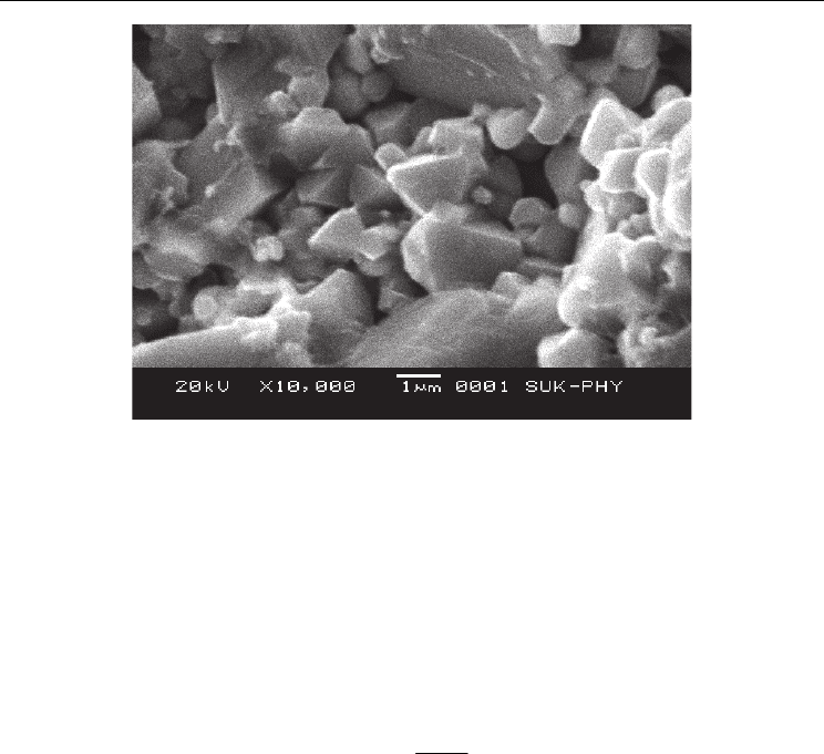
Fig. 4. SEM micrograph of Pb
Zr
0.8
Ti
0.2
O
3
ferroelectric phase
5. DC electrical resistivity
The DC electrical resistivity of the samples are measured by two probe method. For good
electrical contacts, the polished surfaces of pellets are silver coated on both sides and
mounted in the sample holder. Afterwords it is placed in the digital temperature controlled
muffle furnace and a constant voltage about 5 volts is applied using stabilized power supply
unit and the current at different temperature is measured using digital nano ammeter. The
resistivity of all the samples
DC
ρ
(ohm-cm) was estimated by measuring the current at the
fixed voltage (ohm’s law).
2
DC
Rr
t
π
ρ
= (1)
Where t - thickness of the pellet (cm), r - radius of the pellet (cm) and R- resistance (ohm).
The variation of DC resistivity with temperature for (x) Ni
0.2
Co
0.8
Fe
2
O
4
+ (1-x) Ba
0.8
Pb
0.2
Zr
0.8
Ti
0.2
O
3
composites (with x = 0.0, 0.15, 0.30, 0.45 and 1.0) are presented elsewhere
12
. The
first region among the two regions of conductivity, observed at lower temperature is
attributed to ordered states of the ferroelectric phase and the second region observed at
higher temperature due to polaron hopping is attributed to the disordered para electric
states of the composites. However, the impurities present in the system are almost
minimized at higher temperature. Polaron hopping is valid in ferroelectrics as well as in
composites containing ferrite and ferroelectrics
13
. According to hopping conduction
mechanism the resistivity of composites are found to decrease with increase in ferrite
content (due to its low resistivity compared to ferroelectric phase). The ferrite particles
disperse throughout the composites and make connected chains with the ferroelectric
particles which reduces resistivity significantly. Good dispersion of the ferrite particles are
required to obtain high electrical conductivity in the composites. The electrical conductivity
in ferrites are explained on the basis of Verwey de Boer mechanism, as it involves the
electron exchange between ions of same element which are already present in more than one

Ferroelectrics - Characterization and Modeling
270
valance state and distributed randomly over the crystallographic equivalent lattice sites. The
resistivity of the composite is the sum of the resistivities of their constituents
14
and the
decrease in resistivity with increase in temperature is attributed to the increase in drift
mobility of charge carriers. During the process of preparation, the formation of Fe
2+
and Fe
3+
ions depends on the sintering condition. But large drop in resistivity is observed on the
addition of a ferrite phase to the composites, it is due to the partial reduction of Fe
2+
and
Fe
3+
ions at elevated firing temperatures. While preparing the mixtures of two phases to get
high ME response in the composites the control of the resistivity of the ferrite phase is
necessary compared to ferroelectric phase. Similar results have been identified in the
temperature dependent resistivity plot for the (x) Ni
0.2
Co
0.8
Fe
2
O
4
+ (1-x) Pb
Zr
0.8
Ti
0.2
O
3
composites with x = 0.0, 0.15, 0.30, 0.45 and 1.0
15
.
The variation of DC electrical resistivity with temperature for (x) Ni
0.5
Zn
0.5
Fe
2
O
4
+ (1-x)
Ba
0.8
Pb
0.2
Zr
0.8
Ti
0.2
O
3
composites with x = 0.0, 0.15, 0.30, 0.45 and 1.0 is also presented earlier
16
. The resistivity of the composites decreases with increase in ferrite content and the
increase in resistivity with temperature is due to the increase in drift mobility of the charge
carriers. However, the conduction in ferrite may be due to the hopping of electron from Fe
2+
and Fe
3+
ions. The number of such ion pairs depends upon the sintering conditions and
which accounts for the reduction of Fe
3+
to Fe
2+
at elevated temperatures. That is the
resistivity of ferrite is controlled by the Fe
2+
concentration on the B-site. In Ni-ferrite, Ni ions
enter the lattice in combination with Fe
3+
ions resulting in a lower concentration of Fe
2+
ions
with higher resistivity and which is one of the prime requirements for getting higher values
of ME output. According to theoretical predictions the plots of ferroelectric phase and
composites show two regions of conductivity and the change in slope is due to the transition
of the sample from the ferroelectric state to para electric state. However, the regions
observed above and below the Curie temperature may be due to the impurities and small
polaron hopping mechanism.
The mobility is temperature dependent quantity and can be characterized by the activation
energy. But at the grain boundaries, the highly disturbed crystal lattice may cause a drastic
decrease in the activation energy. The activation energy in the present case is obtained by
fitting the DC resistivity data with the Arrhenius relation ρ = ρ
o
exp (ΔE/KT), where ΔE is
the activation energy and K is Boltzmann constant. It is well known that the electron and
hole hopping between Fe
2+
/Fe
3+
and Zn
2+
/Zn
3+
, Ni
2+
/Ni
3+
, Ba
2+
/Ba
3+
, Ti
3+
/Ti
4+
ions is
responsible for electrical conduction in the composites. The estimated activation energies for
the composites in the higher and lower temperature regions suggest temperature dependent
charge mobility and activation energy of paraelectric region greater than 0.2 eV (above Tc),
reveals polaron hoping in composites. Similar behavior is observed for (x) Ni
0.5
Zn
0.5
Fe
2
O
4
+
(1-x) PbZr
0.8
Ti
0.2
O
3
composites (with x = 0.0, 0.15, 0.30, 0.45 and 1.0). In case of composites,
the temperature dependent variation of resistivity is very important for the measurements
of ME conversion factor, because the conduction in composites being thermally activated
mechanism, alters the polarization of the ferroelectric phase as temperature increases. Thus
the ME measurements are carried out only at the room temperature
17
.
6. Dielectric properties and AC conductivity
6.1 AC conductivity measurements
The temperature dependent AC conductivity (σ
AC
) are related to the dielectric relaxation
caused by the localized electric charge carriers. And the frequency dependent AC
conductivity is estimated from dielectric constant and loss tangent (tanδ) using the relation

The Ferroelectric Dependent Magnetoelectricity in Composites
271
σ
AC
= ε′ ε
o
2πf tan δ (2)
Where, ε′ is real dielectric constant, ε
o
is the permittivity of free space, tanδ is the loss
tangent at real ε′ (at dielectric constant) and f is the frequency of applied field. However, the
conduction mechanism in composites are obtained from the plots of frequency response of
the dielectric behavior and AC conductivity.
6.2 Variation of dielectric constant (ε΄) and loss tangent (tanδ)
The variation of dielectric constant with frequency at room temperature for the four composite
systems shows good response and are reported elsewere
12
. The dielectric constant decreases
with increase in test frequency indicating dispersion in certain frequency region and then
reaches a constant value. The high values of dielectric constant at lower frequency region and
low values at higher frequency region indicate large dispersion due to Maxwell-Wagner
18, 19
type of interfacial polarization in accordance with Koop’s theory. At lower frequencies the
dielectric constants of ferrites, ferroelectrics and their composites vary randomly. It is due to
the mismatching of grains of ferrites and ferroelectrics in the composites and hence it is
difficult to estimate the effective values of dielectric constant of composites.
The decrease in dielectric constant with increase in frequency indicating dielectric
dispersion due to dielectric polarization. Dielectric polarization is due to the changes in the
valence states of cations and space charge polarization mechanism. At higher frequencies,
the dielectric constant is independent of frequency due to the inability of the electric dipoles
to follow up the fast variation of the applied alternating electric field and increase in friction
between the dipoles. However, at lower frequencies the higher values of the dielectric
constant are due to heterogeneous conduction; some times it is because of polaron hopping
mechanism resulted in electronic polarization contributing to low frequency dispersion. In
composites due to the friction, the dipoles dissipate energy in the form of heat which affects
internal viscosity of the system and results in decrease of the dielectric constant; this
frequency independent parameter is known as static dielectric constant. The dielectric
behavior in composites can also be explained on the basis of polarization mechanism in
ferrites because conduction beyond phase percolation limit is due to ferrite. In ferrites, the
rotational displacement of Fe
3+
↔ Fe
2+
dipoles results in orientation polarization that may
be visualized as an exchange of electrons between the ions and alignment of dipoles
themselves with the alternating field. In the present ferrites, the presence of Ni
2+
/Ni
3+
,
Co
2+
/Co
3+
and Zn
2+
/Zn
3+
ions give rise to p-type carriers and also their displacement in the
external electric field direction contributes to the net polarization in addition to that of n-
type carriers. Since the mobility of p-type carriers is smaller than that of n-type carriers, their
contribution to the polarization decreases more rapidly even at lower frequency. As a result,
the net polarization increases initially and then decreases with increase in frequency. The
transport properties such as electrical conductivity and dielectric dispersion of ferrites are
mainly due to the exchange mechanism of charges among the ions situated at
crystallographic equivalent sites
20
. Iwauchi
21
and Rezlescu et al have established inverse
relation between conduction mechanism and dielectric behavior based on the local
displacement of electrons in the direction of applied field.
The variation of dielectric loss factor (tanδ) with frequency was also explained. At lower
frequencies loss factor is large and it goes on decreasing with increase in frequency. The loss
factor is the energy dissipation in the dielectric system, which is proportional to the
imaginary part of the dielectric constant (ε′′). At higher frequencies, the losses are reduced
due to serial arrangements of dipoles of grains which contribute to the polarization. The
losses can also be explained in terms of relaxation time and the period of applied field.
Ferroelectrics - Characterization and Modeling
272
When loss is minimum, then relaxation time is greater than period of applied field and it is
maximum when relaxation time is smaller than the period of applied field.
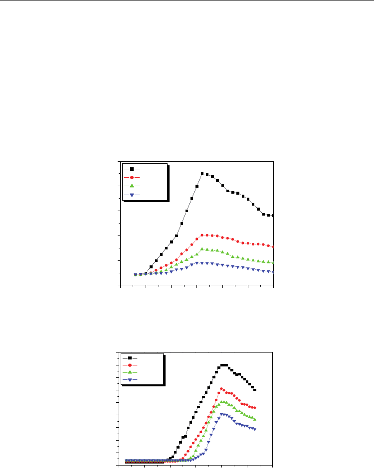
6.3 Ferroelectric phase
The variations of dielectric constant with temperature for two ferroelectric systems (BPZT
and PZT) are shown in figs (5 & 6). The dielectric constant increases with increase in
temperature and becomes maximum at Curie temperature (T
c
) and there after it decreases.
For BPZT and PZT ferroelectrics, the observed T
c
are nearly 160
o
C and 410
o
C, slightly
greater than the reported values and can be attributed to constrained grains. Hiroshima et al
22
have reported a close relation between the Curie temperature and internal stresses
developed in the constrained grains at the phase transition temperature. The internal stress
can shift T
c
to higher temperature sides in case of larger grains (diameter greater than 1 μm).
0 50 100 150 200 250 300
0
1000
2000
3000
4000
5000
1KHz
10KHz
100KHz
1MHz
Dielectric constant (ε')
Temperature (
O
C)
Fig. 5. Variation of dielectric constant with temperature for Ba
0.8
Pb
0.2
Zr
0.8
Ti
0.2
O
3
ferroelectric
phase
0 100 200 300 400 500 600
0
1000
2000
3000
4000
5000
6000
7000
8000
9000
1KHz
10KHz
100KHz
1MHz
Dielectric constant (ε')
Temperature (
O
C)
Fig. 6. Variation of dielectric constant with temperature for Pb
Zr
0.8
Ti
0.2
O
3
ferroelectric phase
The larger grained structure and changes in internal stresses are expected in the pellets due
to higher sintering temperature. The large grained ferroelectrics have considerable internal
The Ferroelectric Dependent Magnetoelectricity in Composites
273
stress concentration which is enough to form micro cracks at the grain boundaries and hence
induced internal stresses are relieved. But in small grain sized ceramics, increased grain
boundaries form less micro cracks which reduce the internal stress concentration. Usually
the ferroelectric materials have high dielectric constant compared to ferrite; hence dielectric
property is enhanced with the increase in ferroelectric content, which is very important in
the study of ME output
12
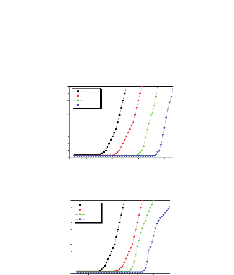
. The nature of variation of dielectric loss tangent with temperature
for all the series of composites and their constituent phases shown in figures (7 & 8), almost
the same as that of the variation of dielectric constant with temperature. The observed
dispersion behavior of the loss tangent is attributed to higher domain mobility near the
Curie temperature.
0 100 200 300 400 500 600
0
2
4
6
8
10
1KHz
10KHz
100KHz
1MHz
tanδ
Temperature (
O
C)
Fig. 7. Variation of dielectric loss tangent with temperature for Ba
0.8
Pb
0.2
Zr
0.8
Ti
0.2
O
3
ferroelectric phase
0 100 200 300 400 500 600
0
2
4
6
8
10
1KHz
10KHz
100KHz
1MHz
tanδ
Temperature (
O
C)
Fig. 8. Variation of dielectric loss tangent with temperature for Pb
Zr
0.8
Ti
0.2
O
3
ferroelectric phase
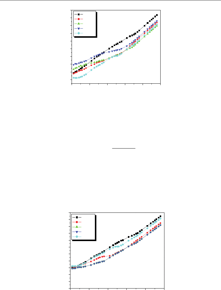
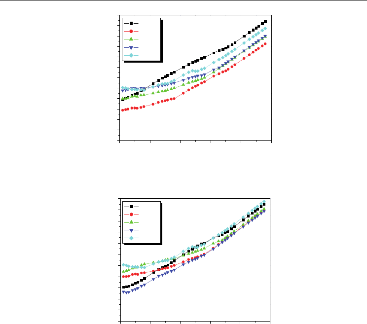
6.4 Variation of AC conductivity with frequency at room temperature
The variation of AC conductivity (σ
AC
) as a function of frequency was presented in figures
(9 - 12). From AC conductivity one can retrieve at the behaviour of thermally activated
conduction mechanism and the type of polarons responsible for the conduction mechanism.
Ferroelectrics - Characterization and Modeling
274
4 6 8 10 12 14
-8.5
-8.0
-7.5
-7.0
-6.5
-6.0
-5.5
-5.0
-4.5
-4.0
Log (σ
ac
-σ
dc
)
Log ω
2
x=0.00
x=0.15
x=0.30
x=0.45
x=1.00
Fig. 9. Variation of AC conductivity with frequency for (x) Ni
0.2
Co
0.8
Fe
2
O
4
+ (1-x) Ba
0.8
Pb
0.2
Zr
0.8
Ti
0.2
O
3
composites
Infact the polaron type of conduction was reported by Austin and Mott
23
and Appel et al.
According to Alder and Feinleib
24
the direct frequency dependence conduction due to small
polarons is given by the relation
()
22
22
1
AC DC
ωτ
σσ
ωτ
−=
−
(3)
Where ω is the angular frequency and τ is the staying time (10
-10
s), for all the ceramics ω
2
τ
2
< 1. The plots of log (σ
AC
-σ
DC
) against Log ω
2
are linear in nature indicating small polaron
type of conduction. However, a slight decrease in the conductivity at a certain frequency is
attributed to mixed polaron (small/large) type of conduction and similar results are
reported by various workers. In the present case, the AC conductivity of the composites
caused by small polarons is responsible for the good ME response.
4 6 8 10 12 14
-10.0
-9.5
-9.0
-8.5
-8.0
-7.5
-7.0
-6.5
-6.0
-5.5
-5.0
-4.5
Log (σ
ac
-σ
dc
)
Log ω
2
x=0.00
x=0.15
x=0.30
x=0.45
x=1.00
Fig. 10. Variation of AC conductivity with frequency for (x) Ni
0.2
Co
0.8
Fe
2
O
4
+ (1-x) Pb
Zr
0.8
Ti
0.2
O
3
composites
The Ferroelectric Dependent Magnetoelectricity in Composites
275
468101214
-10.0
-9.5
-9.0
-8.5
-8.0
-7.5
-7.0
-6.5
-6.0
-5.5
-5.0
-4.5
-4.0
Log (σ
ac
-σ
dc
)
Log ω
2
x=0.00
x=0.15
x=0.30
x=0.45
x=1.00
Fig. 11. Variation of AC conductivity with frequency for (x) Ni
0.5
Zn
0.5
Fe
2
O
4
+ (1-x) Ba
0.8
Pb
0.2
Zr
0.8
Ti
0.2
O
3
composites
4 6 8 10 12 14
-10.0
-9.5
-9.0
-8.5
-8.0
-7.5
-7.0
-6.5
-6.0
-5.5
-5.0
-4.5
Log (σ
ac
-σ
dc
)
Log ω
2
x=0.00
x=0.15
x=0.30
x=0.45
x=1.00
Fig. 12. Variation of AC conductivity with frequency for (x) Ni
0.5
Zn
0.5
Fe
2
O
4
+ (1-x) Pb
Zr
0.8
Ti
0.2
O
3
composites
7. Magnetoelectric effect- A product property
Magnetoelectricity, the product property, requires biphasic surrounding to exhibit the
complex behaviour. The primary magnetoelectric (ME) materials can be magnetized by
placing them in electric field and can be electrically polarized by placing them in magnetic
field
25
. The magnetoelectric effect in the composites having ferrite and ferroelectric phases
depends on the applied magnetic field, electrical resistivity, mole percentage of the constituent
phases and mechanical coupling between the two phases. The resistivity of the composites is a
temperature dependent property which decreases in high temperature region, making the
polarization of the samples more difficult. In the present studies the ME voltage coefficient is
measured at room temperature. The ME coupling can be obtained by electromechanical
conversion in the ferrite and ferroelectric phases by the transfer of stress through the interface
between these two phases. Infact magneto mechanical resonance in the ferrite phase and
electromechanical resonance in ferroelectric phase are responsible for the origins of ME peaks.
Ferroelectrics - Characterization and Modeling
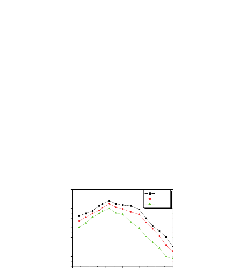
276
For the composite systems (x) Ni
0.2
Co
0.8
Fe
2
O
4
+ (1-x) Ba
0.8
Pb
0.2
Zr
0.8
Ti
0.2
O
3
(with x = 0.15, 0.30
and 0.45) the variation of static magnetoelectric conversion factor with applied DC magnetic
field is shown in fig. 13. From the figure it is clear that magnetoelectric voltage coefficient
(dE/dH)
H
increases slowly with applied magnetic field and after attaining a maximum value
again it decreases. The constant value of (dE/dH)
H
indicates that the magnetostriction reaches
its saturation value at the time of magnetic poling and produces constant electric field in the
ferroelectric phase. The static ME conversion factor depends on mole % of ferrite and
ferroelectric phases in the composites, however with further increase in mole fraction of ferrite
phase, the maganetoelectric voltage coefficient (dE/dH)
H
decreases. The lower values of static
ME output are due to low resistivity of ferrite phase compared to that of ferroelectric phase. At
the time of poling, charges are developed in the ferroelectric grains through the surrounding
of low resistivity ferrite grain and leakage of such charges is responsible for low static ME
output. However, the static magnetoelectric voltage coefficient (dE/dH)
H
decreases with
increase in grain size of the ferrite and ferroelectric phases in the composites. The large grains
are (polydomain) less effective in inducing piezomagnetic and piezoelectric coefficients than
that of the smaller ones
26
. Motagi and Hiskins reported the variation of piezoelectric property
of ferroelectric phase with grain size. Infact the ME conversion factor also depends on porosity
and grain size. In the present experimental investigation it is found that small grains with low
porosity are important for getting high ME out put in the composites. A maximum static ME
coefficient of 536 μV/cm Oe is observed in the composite containing 15 % Ni
0.2
Co
0.8
Fe
2
O
4
+ 85
% BPZT (table. 1). The observed results for the composite system (x) Ni
0.2
Co
0.8
Fe
2
O
4
+ (1-x) Pb
Zr
0.8
Ti
0.2
O
3
(with x = 0.15, 0.30 and 0.45) are shown figure. 14. The high ME out put of 828
μV/cm Oe is observed for the composite containing 15 % Ni
0.2
Co
0.8
Fe
2
O
4
+ 85 % Pb
Zr
0.8
Ti
0.2
O
3
(table 1). High magnetostriction coefficient and piezoelectric coefficient of the ferrite and
ferroelectric phases are responsible for high ME out put in these composites.
0 1000 2000 3000 4000 5000 6000
400
420
440
460
480
500
520
540
560
x=0.15
x=0.30
x=0.45
(dE/dH)
H
μV/cm.Oe
H (Oe)
Fig. 13. Magnetic field dependent variation of ME voltage coefficient at room temperature
for (x) Ni
0.2
Co
0.8
Fe
2
O
4
+ (1-x) Ba
0.8
Pb
0.2
Zr
0.8
Ti
0.2
O
3
ME composites.
From the investigation it is observed that increase in ferrite content in the composites leads
to the enhancement of elastic interaction. But there is a limit to the addition of ferrite in the
composite because further increase in ferrite content in the composites leads to the decrease
in the resistivity of composites. Therefore the additions of ferrites in the composites are
restricted to only 0.15, 0.30 and 0.45, because at these values there is a resistivity matching
The Ferroelectric Dependent Magnetoelectricity in Composites
277
between ferrite and ferroelectric phases. Many workers studied Ni, Co and Zn ferrite with
BaTiO
3
ferroelectric by ceramic method and reported very weak ME response inspite of high
resistivity of the ferrites. But in the present composites better ME voltage coefficients are
obtained, which may be due to the presence of cobalt ions (Co
+2
) in ferrites, as it causes large
lattice distortion in the ferrite lattice and induces more mechanical coupling between the
ferrite and ferroelectric phases, leading to the polarization in the piezoelectric phases.
Similarly substitution of Zn in nickel also enhances the magnetostriction coefficient and
hence shows good ME response.
0 1000 2000 3000 4000 5000 6000
720
740
760
780
800
820
840
860
x=0.15
x=0.30
x=0.45
(dE/dH)
H
μV/cm Oe
H (Oe)
Fig. 14. Magnetic field dependent variation of ME voltage coefficient at room temperature
for (x) Ni
0.2
Co
0.8
Fe
2
O
4
+ (1-x) Pb
Zr
0.8
Ti
0.2
O
3
ME composites.
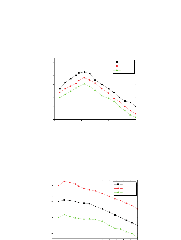
The magnetic field dependent variation of the ME voltage coefficient with magnetic field for
the composite system (x) Ni
0.5
Zn
0.5
Fe
2
O
4
+ (1-x) Ba
0.8
Pb
0.2
Zr
0.8
Ti
0.2
O
3
is shown in fig 15. The
ME coefficient increases linearly with applied magnetic filed (< 1.0 K Oe) and after acquiring
a maximum value decreases linearly. The initial rise in ME output is attributed to the
enhancement in the elastic interaction, which is confirmed by the hysteresis measurements.
0 1000 2000 3000 4000 5000 6000
600
620
640
660
680
700
x=0.15
x=0.30
x=0.45
(dE/dH)
H
μV/cm.Oe
H (Oe)
Fig. 15. Magnetic field dependent variation of ME voltage coefficient at room temperature
for (x) Ni
0.5
Zn
0.5
Fe
2
O
4
+ (1-x) Ba
0.8
Pb
0.2
Zr
0.8
Ti
0.2
O
3
ME composites.

Ferroelectrics - Characterization and Modeling
278
The intensity of the magnetostriction reaches saturation value above 1.0 K Oe and hence, the
magnetization and associated strain produce a constant electric field in the ferroelectric
phase beyond the saturation limit. The maximum ME voltage coefficient of 698 μV/cm Oe is
observed for the composites containing 30 % Ni
0.5
Zn
0.5
Fe
2
O
4
+ 70 % Ba
0.8
Pb
0.2
Zr
0.8
Ti
0.2
O
3
(table. 1). It is well known that the ME response of the composites depends on the
piezoelectricity of the ferroelectric phase and the magnetostriction of the ferrite phase. The
composites prepared with a lower content of the ferrite or ferroelectric phase results in the
reduction of piezoelectricity or magnetostriction respectively, leading to a decrease in the
static ME voltage coefficient as predicted theoretically. The increase in ME output at x = 0.30
(table. 1) may be attributed to the uniform distribution of small grains in both the phases.
However, the uneven particle size of the phases reduces the mechanical coupling between
them and causes significant current loss in the sample
27
. The similar results have been
observed for the composite system (x) Ni
0.5
Zn
0.5
Fe
2
O
4
+ (1-x) Pb
Zr
0.8
Ti
0.2
O
3
(with x = 0.15,
0.30 and 0.45) shown in fig. 16.
Composition (x)
ME Voltage Coefficient (dE/dH)
H
(μV/cm Oe)
(x) Ni
0.2
Co
0.8
Fe
2
O
4
+ (1-x) Ba
0.8
Pb
0.2
Zr
0.8
Ti
0.2
O
3
0.15 536
0.30 530
0.45 520
(x) Ni
0.2
Co
0.8
Fe
2
O
4
+ (1-x) Pb
Zr
0.8
Ti
0.2
O
3
0.15 828
0.30 815
0.45 801
(x) Ni
0.5
Zn
0.5
Fe
2
O
4
+ (1-x) Ba
0.8
Pb
0.2
Zr
0.8
Ti
0.2
O
3
0.15 663
0.30 698
0.45 635
(x) Ni
0.5
Zn
0.5
Fe
2
O
4
+ (1-x) Pb
Zr
0.8
Ti
0.2
O
3
0.15 839
0.30 808
0.45 783
Table. 1. Variation of ME Voltage Coefficient with composition