Каталог - Шахтные подъемные машины НКМЗ (2005)
Подождите немного. Документ загружается.


« »
-
- -
-
-
. ! 70 -
" #$ -
" %.
& ' -
() !. *" -
' -
, +/
10 , ,
4…9 . # / -
, + "
" ' 2x5x2,3
!. # -
+
- , -
' . * 1935 . -
“)"” -
«». 6/
“Novokramatorsky Machinostroitelny Zavod” JSC is one of
the Europe’s largest production and engineering complexes
well-known for the customers in the mining, iron and steel-
making and power generation industries. Over a period of 70
years NKMZ, has been known as the recognized leader in the
heavy engineering industry in the CIS and as a reliable partner
of the reputed manufacturers in Europe.
Mine winders are the oldest products of JSC NKMZ. Abil-
ity of output a huge drum mine winders is determined by the
presence of manufacturing equipment, which allows to pro-
duce blanks and to machine shafts of 10 m length, large-grain
gearboxes, drums with a diameter of 4...9 m. Our engineers
in the Design Office had already been designing drawings of
the first huge mine winder of 2x5x2,3 to manufacture at NKMZ
when building of the plant was not finished yet. Simultane-
ously with the plant starting up we began manufacturing of
this machine and organized design office of mining equip-
ment, which designed mine winders. In 1935 the first machine
for the “Ordzhonikidze” mine of “Makeevugol” trust was de-
signed. The double-drum mine winders 2x4x1,8 and 2x6x2,4
and single-drum mine winder 1x4,2x2,0 were designed before
the war. There were 30 winders for Donbass and Kuzbass
mines manufactured. In 1946 NKMZ produced the first friction
1935 2005
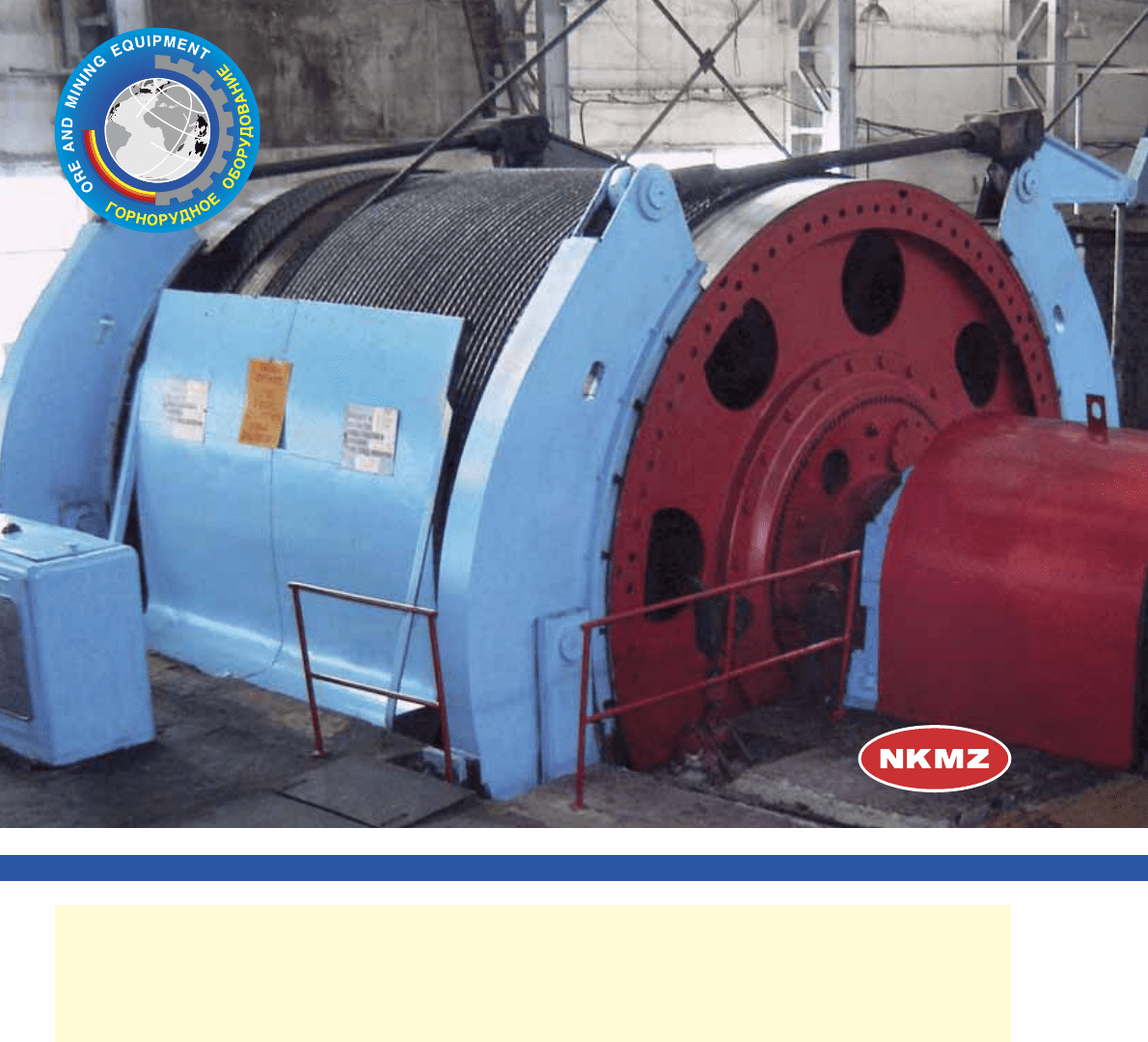
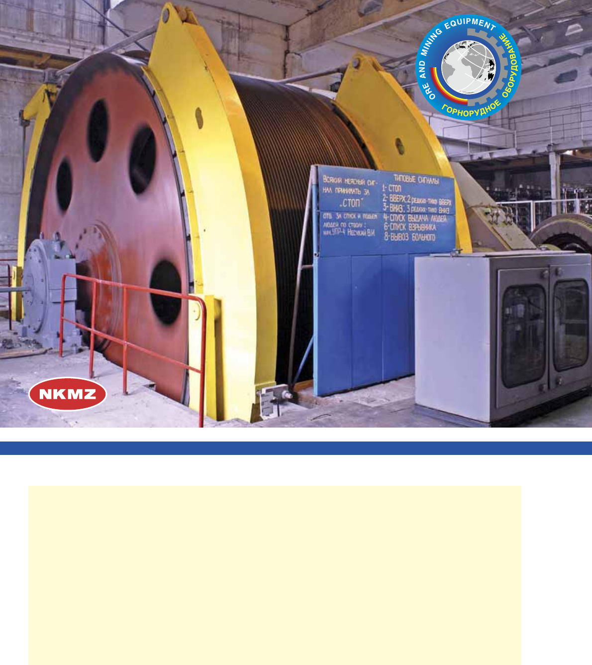
# ' .
Assembly of the first mine winder.
& ' ;&.
;& Mine Winder.
<)##=>
?<(=(
$6<(=>
=@(B
F6G=>
H)LP&(
<?Q=>
R)L$(<=>
#.)<6>
R6L)<?#P
?R(
=<(
(!(G#@(
(<6=>
Q<$Q!#@(
?!R6=#@(
)$)L=>
$<?!=>
@(UV==#@(
RUSSIA
UKRAINE
GERMANY
CHINA
CZECHIA
POLAND
ROMANIA
BULGARIA
N.KOREA
BYELORUS
CUBA
IRAN
KAZAKHSTAN
ARMENIA
KIRGHIZSTAN
UZBEKISTAN
MONGOLIA
GEORGIA
TADJIKISTAN
' 2x41,8
2x62,4, " 1x4,2x2,0. *-
/ 30 '
U . * 1946 .
&@-7,2 1000
, 1948 . - '
, 1954 . - -
, 1958 . – '
. # 1982 . + '
HR, + -
" . # -
/ 2200 ' .
# &H “!”
?, . ) +
20 , -
" %% /
. * -
' -
+: , -
/ /
;
% + " .
pulley machine &@-7,2 with a mine depth of 1000 m, in 1948
the mine winder with the two-cylinder tapered drum, in 1954
the cylinder split-drum mine winder and in 1958 the multirope
mine winders. In 1982 NKMZ manufactures the mine winders
of the HR series. A distinctive feature of these mine winders
is that they are fitted with brake mounted in the drum. There
are over 2200 mine winders produced from the most begin-
ning of the manufacturing.
Recently, the mine winders bearing the trade mark of NKMZ
are very popular both in Ukraine and abroad. Being in service
at the mines in almost 20 countries, these machines proved
to be the safe and high-performance helpers of the miners.
Depending upon the interaction between mine winder rope
traction element and working member, the drum and reel-
type machines, in which the traction member is moved by
its winding to the drum or reel with a rope friction pulley and
multiple-rope with a friction coupling between the rope and
the friction pulley.
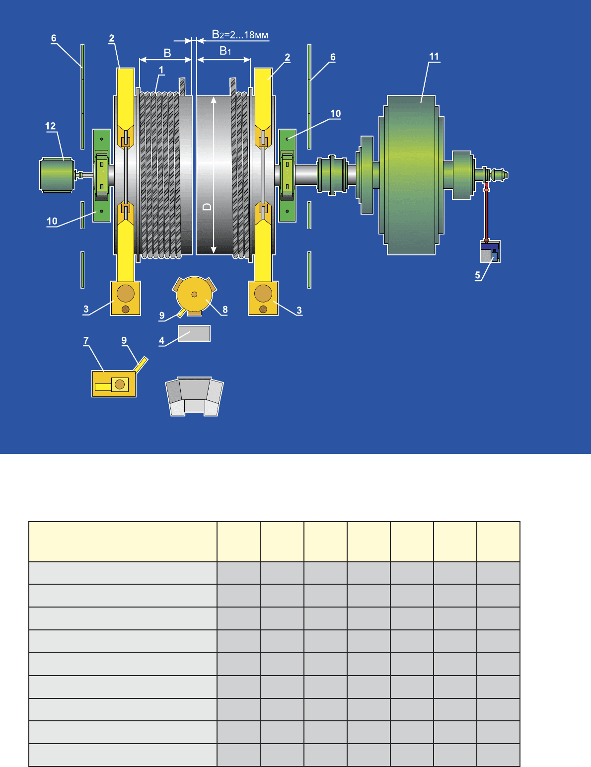
&(G@(> H)U|6(> (&=( 1-6,3G4,95/1,4
1-6.3x4.95/1.4 MINE WINDER
(&=Q H)U|6Q6 &(G@Q6 # (<?VQ <(#H)L)V6=6 @)<)!)*
# ;=L=U<=F6#= <(!<6!Q R(<(R()
MINE WINDERS WITH OUTBOARD BRAKES AND CYLINDER SPLIT-DRUM
H' -
+
', "
' .
) +
,
+ '-
, "
+ -
.
U "-
,
- , ,
- - / "-
. " , -
, " -
, .. -
. * ,
, .
"
, (
- , - ),
" , -
- ".
H' " -
, -
/ / 100
- 150 -
,
+.
A single-cylinder split-drum mine winder is used for one-
layer rope winding during skip and two-cage hoisting as well
as for one-apparatus counterbalanced hoisting.
A distinctive feature of the single cylinder split-drum winder
is that it provides concurrent operation of the hoisting plant on
several levels with the distance between them being depend-
ent on the movable drum coiling length.
To provide quick rope length setting upon its stretching or
cutting off for tests, a wedged portion of the drum is bolted to
the shaft while the movable portion is connected to the shaft
with the spring-type air-operated toothed uncoupling device.
The bottom rope affixed on the wedged portion of the drum
may be wound up to the drum split, i.e. to its movable portion.
The top rope secured on the movable portion of the drum may
pass through the split.
This machine may be provided either with the right-or left-
hand drive assemblies being similar in design. However, with
both drive versions the right rope shall be the top while the left
rope the bottom one.
The mine winder shall be arranged with respect to the head
frame pulleys so that the pulley plane of rotation is shifted
for 100 to 150 mm from the drum plane of split towards the
wedged drum portion thus providing the rope pass-over from
the movable drum portion to the wedged one.
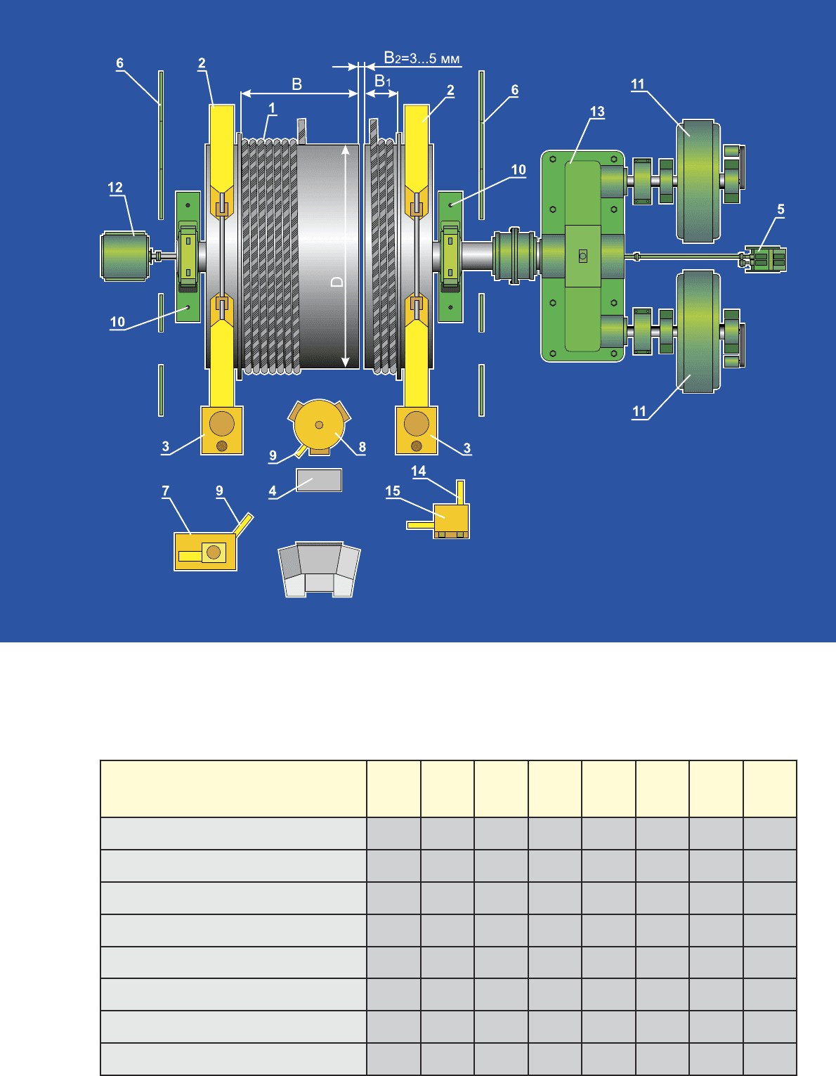
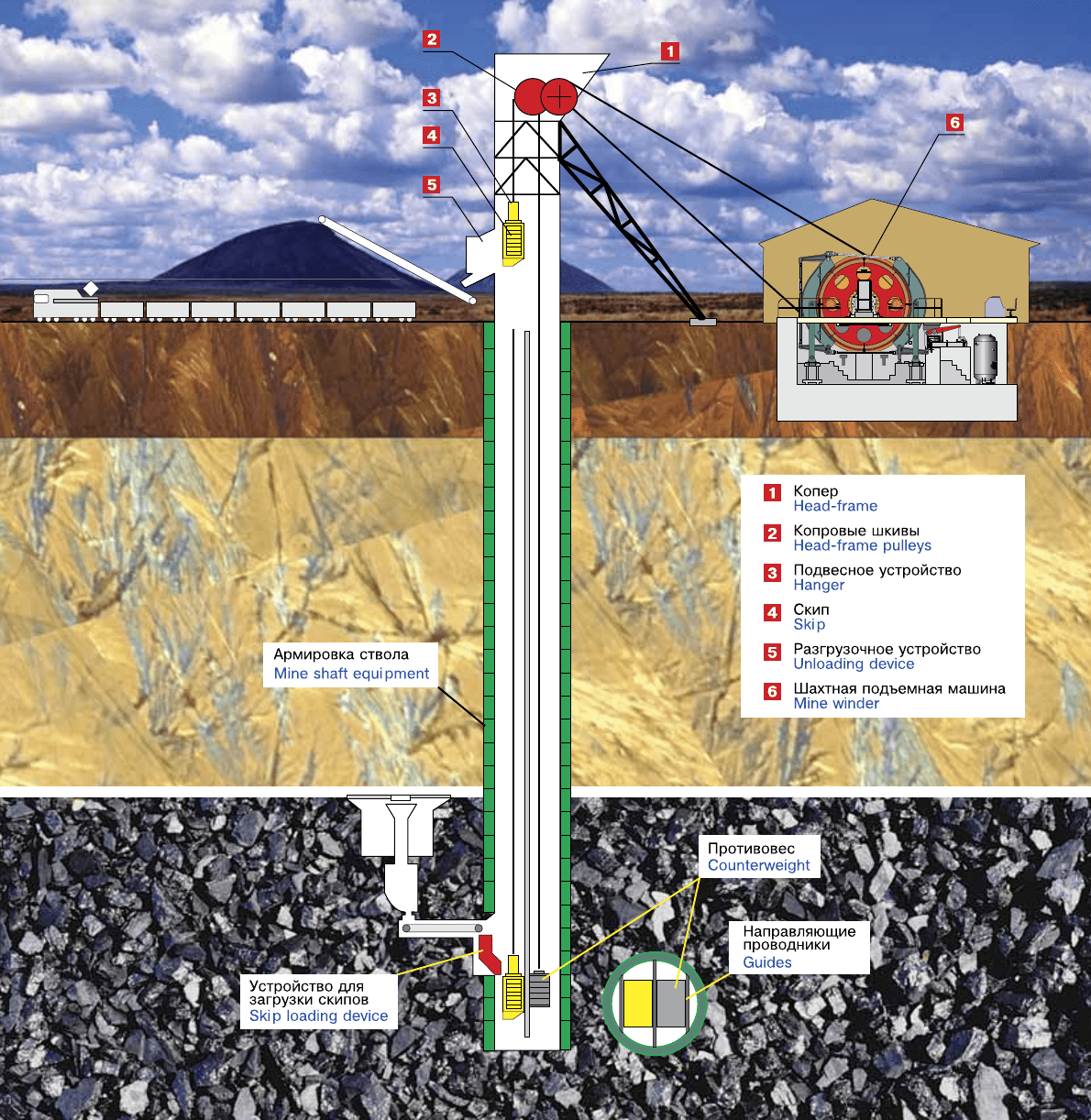
1 - ; 2 - ; 3 - ; 4 - ; 5 - +-
/; 6 - "; 7 - - ; 8 - ; 9 - ;
10 - ; 11 - ' ; 12 - ; 13 - ;
14 - ; 15 -
1 – Drums as assemblies. 2 – Brake. 3 – Brake drive. 4 – Control panel. 5 – Standby speed limiter. 6 – Safeguard. 7 – Com-
pressed air plant. 8 – Air collector. 9 – Pneumatic piping and fittings. 10 – Set of anchor parts. 11 – Hoisting electric motor
s. 12
– Control facilities. 13 – Drive assembly. 14 – Lubrication piping and fittings. 15 – Lubrication plant.
@ '
Mine winder type
D,
B,
B
1
,
n
layers
P,
Pst, kN
no more
P,
Pst, kN
no more
V, /
V, m/s
no more
,
Weight,
t
;<-43/0,7
ÖÐ-4õ3/0,7 with drive assembly
4000 2300 700 1 250 160 12 108
;<-53/0,6
ÖÐ-5õ3/0,6 with drive assembly
5000 2400 600 1 280 210 14 161
;<-63/0,6
ÖÐ-6õ3/0,6 with drive assembly
6000 2400 600 1 320 240 16 177
1-63,4/0,6
1-6õ3,4/0,6 with drive assembly
6000 2800 600 1 320 270 16 189
1-6,33,78/0,63
1-6,3õ3,78/0,63 with drive assembly
6300 3150 630 1 360 195 16 205
1-6,34,2/0,63
1-6,3õ4,2/0,63 with drive assembly
6300 3570 630 1 335 204 16 206
1-6,34,95/0,63
1-6,3õ4,95/0,63 with drive assembly
6300 4320 630 1 385 257 16 218
1-6,34,95/1,4
1-6,3õ4,95/1,4 with drive assembly
6300 3550 1400 1 360 270 16 219
)U)R(<(R(Q6
# )U= ;=L=U<=F6#=
<(!<6!Q R(<(R()
# <6U?@)<Q H<=*)U)
SINGLE-DRUM GEAR-DRIVEN
MINE WINDERS
WITH A SINGLE CYLINDER SPLIT-DRUM
, +
Machine weights are given tentatively and will be refined upon signing the supply contract
" ( )
We are ready to consider an opportunity of manufacturing of other (under requirements of the customer) standard sizes of machines

1 - ; 2 - ; 3 - ; 4 - ; 5 - +-
/; 6 - "; 7 - - ; 8 - ; 9 - ;
10 - ; 11 - ' ; 12 -
1 – Drums as assemblies. 2 – Brake. 3 – Brake drive. 4 – Control panel. 5 – Standby speed limiter. 6 – Safeguard. 7 – Com-
pressed air plant. 8 – Air collector. 9 – Pneumatic piping and fittings. 10 – Set of anchor parts. 11 – Hoisting electric motor. 12
– Control facilities.
@ '
Mine winder type
D,
B,
B
1
,
n
layers
P,
Pst, kN
no more
P,
Pst, kN
no more
V, /
V, m/s
no more
,
Weight,
t
;<-53/0,6
ÖÐ-5õ3/0,6 without drive assembly
5000 2400 600 1 280 210 14 102
;<-54,71/0,5
ÖÐ-5õ4,71/0,5 without drive assembly
5000 4210 500 1 400 300 16 210
;<-55,6/0,8
ÖÐ-5õ5,6/0,8 without drive assembly
5000 4800 800 1 560 400 16 244
;<-63/0,6
ÖÐ-6õ3/0,6 without drive assembly
6000 2400 600 1 320 240 16 113
;<-63,4/0,6
ÖÐ-6õ3,4/0,6 without drive assembly
6000 2800 600 1 360 270 16 125
1-65,6/0,8
1-6õ5,6/0,8 without drive assembly
6000 4800 800 1 560 400 16 250
1-6,33,78/0,63
1-6,3õ3,78/0,63 without drive assembly
6300 3150 630 1 360 195 16 141
1-6,34,2/0,63
1-6,3õ4,2/0,63 without drive assembly
6300 3570 630 1 335 204 16 142
1-6,34,95/0,63
1-6,3õ4,95/0,63 without drive assembly
6300 4320 630 1 385 257 16 154
1-6,34,95/1,4
1-6,3õ4,95/1,4 without drive assembly
6300 3550 1400 1 360 270 16 155
)U)R(<(R(Q6
# )U= ;=L=U<=F6#=
<(!<6!Q R(<(R()
# R6!<6U?@)<Q H<=*)U)
SINGLE-DRUM GEAR-LESS
MINE WINDERS
WITH A SINGLE CYLINDER SPLIT-DRUM
, +
Machine weights are given tentatively and will be refined upon signing the supply contract
" ( )
We are ready to consider an opportunity of manufacturing of other (under requirements of the customer) standard sizes of machines

&(G@(> H)U|6(> (&=( 2;-52,4
2; – 5x2,4 MINE WINDER
(&=Q H)U|6Q6 &(G@Q6 U*?GR(<(R(Q6
# (<?VQ <(#H)L)V6=6 @)<)!)*
BOUBLE-DRUM MINE WINDERS WITH OUTBOARD BRAKES
H' -
+ -
',
" ' .
+ ' -
, " -
+ .
U "-
-
, -,
, - - / "-
.
" ,
, ,
+ .
"
, "
, - ".
A two cylinder drum mine winder is used for one-layer and
two-layer rope winding during two-skip and two-cage hoisting
as well as for one-apparatus counterbalanced hoisting.
This machine provides simultaneous operation of the hoist-
ing plant on several levels with the distance between them
dependent on the coiling length of one drum.
To provide quick rope length setting upon its stretching
or cutting off for tests and for a quick level changing, one
wedged drum is bolted to the shaft while the movable drum
is connected to the shaft with the spring-type air-operated
toothed uncoupling device.
The bottom rope affixed on the wedged drum and the top
rope affixed on the movable drum may be wound only to ap-
propriate drums.
This machine may be provided either with the right- or left-
hand drive assemblies. However, with both drive versions the
right rope shall be the top while the left rope the bottom one.
1 - ; 2 - ; 3 - ; 4 - ; 5 - +-
/; 6 - "; 7 - - ; 8 - ; 9 - ;
10 - ; 11 - ' ; 12 -
1 – Drums as assemblies. 2 – Brake. 3 – Brake drive. 4 – Control panel. 5 – Standby speed limiter. 6 – Safeguard. 7 – Com-
pressed air plant. 8 – Air collector. 9 – Pneumatic piping and fittings. 10 – Set of anchor parts. 11 – Hoisting electric motor
.
12 – Control facilities.
@ '
Mine winder type
D,
B;B
1
n
layers
P,
Pst, kN
no more
P,
Pst, kN
no more
V, /
V, m/s
no more
,
Weight, t
2;-52,4
2Ö-5õ2,4 without drive assembly
5000 2400 1 280 210 14 118
2;-52,4U
2Ö-5õ4,4U without drive assembly
5000 2400 2 280 210 14 130
2;-52,8
2Ö-5õ2,8 without drive assembly
5000 2800 1 560 400 14 223
2;-62,4
2Ö-6õ2,4 without drive assembly
6000 2400 1 320 240 16 144
2;-62,4U
2Ö-6õ2,4U without drive assembly
6000 2400 2 320 240 16 158
2;-62,8
2Ö-6õ2,8 without drive assembly
6000 2800 1 360 270 16 152
2;-62,8U
2Ö-6õ2,8U without drive assembly
6000 2400 2 360 270 16 157
2;-62,8?
2Ö-6õ2,8? without drive assembly
6000 2800 1 560 400 16 240
2;-6,33,1
2Ö-6,3õ3,1 without drive assembly
6300 3100 1 560 400 16 290
U*?GR(<(R(Q6
# R6!<6U?@)<Q
H<=*)U)
DOUBLE-DRUM
GEARLESS MINE WINDERS
, +
Machine weights are given tentatively and will be refined upon signing the supply contract
" ( )
We are ready to consider an opportunity of manufacturing of other (under requirements of the customer) standard sizes of machines
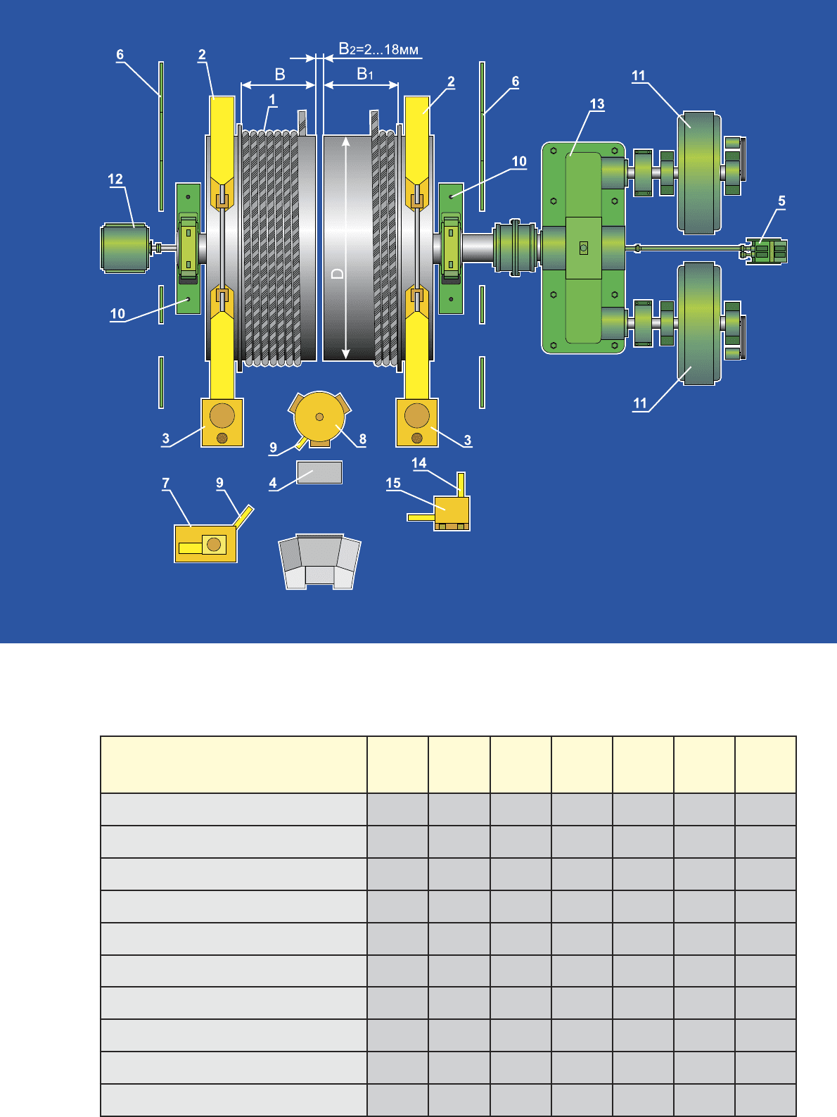
1 - ; 2 - ; 3 - ; 4 - ; 5 - +-
/; 6 - "; 7 - - ; 8 - ; 9 - ;
10 - ; 11 - ' ; 12 - ; 13 - ;
14 - ; 15 -
1 – Drums as assemblies. 2 – Brake. 3 – Brake drive. 4 – Control panel. 5 – Standby speed limiter. 6 – Safeguard. 7 – Com-
pressed air plant. 8 – Air collector. 9 – Pneumatic piping and fittings. 10 – Set of anchor parts. 11 – Hoisting electric motors.
12 – Control facilities.13 – Drive assembly. 14 – Lubrication piping and fittings. 15 – Lubrication plant.
@ '
Mine winder type
D,
B;B
1
n
layers
P,
Pst, kN
no more
P,
Pst, kN
no more
V, /
V, m/s
no more
,
Weight, t
2;-41,8
2Ö-4õ1,8 with drive assembly
4000 1800 1 250 160 12 112
2;-41,8U
2Ö-4õ1,8U with drive assembly
4000 1800 2 250 160 12 118
2;-42,3
2Ö-4õ2,3 with drive assembly
4000 2300 1 250 160 12 116
2;-42,3U
2Ö-4õ2,3U with drive assembly
4000 2300 2 250 160 12 128
2;-52,4
2Ö-5õ2,4 with drive assembly
5000 2400 1 280 210 14 182
2;-52,4U
2Ö-5õ2,4U with drive assembly
5000 2400 2 280 210 14 193
2;-62,4
2Ö-6õ2,4 with drive assembly
6000 2400 1 320 240 16 207
2;-62,4U
2Ö-6õ2,4U with drive assembly
6000 2400 2 320 240 16 222
2;-62,8
2Ö-6õ2,8 with drive assembly
6000 2800 1 360 270 16 216
2;-62,8U
2Ö-6õ2,8U with drive assembly
6000 2800 2 360 270 16 221
U*?GR(<(R(Q6
# <6U?@)<Q
H<=*)U)
DOUBLE-DRUM
GEAR-DRIVEN MINE WINDERS
, +
Machine weights are given tentatively and will be refined upon signing the supply contract
" ( )
We are ready to consider an opportunity of manufacturing of others (under requirements of the customer) standard sizes of machines
&(G@(> H)U|6(> (&=( 1-52,4
1-52,4 MINE WINDER
(&=Q H)U|6Q6 &(G@Q6 )U)R(<(R(Q6
# (<?VQ <(#H)L)V6=6 @)<)!)*
SINGLE-DRUM MINE WINDERS WITH OUTBOARD BRAKES
H' -
+ -
'.
+ ' -
. -
" .
A single cylinder solid-drum mine winders are used for one-
and multi-layer rope winding for one-apparatus hoisting.
The machines of this type are capable of servicing hoisting
from one level.
This machines may be provided either with the right- or left-
hand drive assemblies.