Jackson S.D., Hargreaves J.S.J. Metal Oxide Catalysis
Подождите немного. Документ загружается.

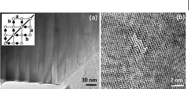
In a crystal containing twin defects, the crystal lattices continue across the twin
boundaries without a break. Another similar defect, the antiphase defect, is formed
by a shift of the crystal by half a unit cell along the antiphase boundary. This defect
can also contribute to strong image contrast as shown in Figure 10.3 b.
10.6.3
Point Defects
Point defects occur where an atom is missing, or is replaced by an impurity
atom or is in an irregular place in the structural lattice. Point defects include self -
interstitial atoms and interstitial impurity atoms in a random arrangement.
Since the defects are very small and disordered, the corresponding diffraction
intensities in SAED and image contrast in HRTEM are normally too low to be
visible. On the other hand, some point defects can cause a local lattice distortion
and the real defect areas are much larger than a single atom. For example, a
vacancy may induce relocation of the atoms towards it or an interstitial atom may
push the surrounding atoms away from their ideal positions. Even a substitutional
atom at an ideal lattice position can cause a local distortion owing to its different
property (size, charge, etc) from those of the atoms in a bulk oxide. In these cases,
it is possible to see the image contrast created by these defects.
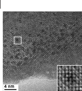
An example of such expanded point defects was demonstrated in the perovskite -
based La
4
Sr
n − 4
Ti
n
O
3 n +2
series [62, 63] . When the n value is small, the amount of
excess oxygen per perovskite unit x
p
in the compound is large. For example, x
p
=
0.5 in La
2
Ti
2
O
7
( n = 4), x
p
= 0.4 in La
4
SrTi
5
O
17
( n = 5), x
p
= 0.333 in La
4
Sr
2
Ti
6
O
20
and so on. To accommodate these excess oxygen anions, the perovskite structures
are broken into blocks so that excess oxygen can be accommodated in between the
blocks. When the n value increases, the dimensions of the blocks increase and the
overall structure approaches that of a perovskite phase. When n is 12, a cubic phase
10.6 Defects in Oxides 467
Figure 10.14 (a) TEM and (b) HRTEM images of YBa
2
Cu
3
O
7
on the [001] projection, showing twin defects. The inset of (a)
is a schematic model of twin defects. In (b), the a axis across
the twin planes is marked by the white lines.
468 10 Transmission Electron Microscopy
is synthesized. However, in this compound, the average value of excess oxygen is
still signifi cant, x
p
= 0.1667 per perovskite unit. These oxygen atoms occupy inter-
stitial sites in the perovskite structure. Since oxygen anions are too large to stay
in any spare space in the perovskite matrix, local distortion must be induced. This
distortion gave us an opportunity to see directly the disordered nature of these
oxygen anions in the compound (Figure 10.15 ). The evidence is crucial in under-
standing the properties of materials developed for application in solid - state fuel
cells [63] .
10.7
Porous Materials
10.7.1
Microporous Zeolites
Microporous zeolites with pore diameters normally smaller than 1 nm (mainly
aluminum silicates) are important industrial materials for catalysis, gas absorption
and so on. Most known crystal structures of zeolites containing corner - sharing
SiO
4
and AlO
4
tetrahedra, were determined by XRD. The principal role of HRTEM
in studying these materials in the last 30 years was to directly image the open
framework structures and therefore to discover the local microstructures. However,
for some new zeolites with very complicated, low symmetry structures, the pore
arrangements revealed by HRTEM are indeed essential to the fi nal solution of the
structures [64, 65] . One example is the determination of a TNU complex zeolite
structure by combining powder diffraction and electron microscopy [66] .
Figure 10.15 HRTEM image of n = 12 member in the
La
4
Sr
n − 4
Ti
n
O
3n +2
series. Randomly distributed local defects are
visible as dark spots. The inset is an enlarged image of a
single defect.
Zeolite - β , as an excellent catalyst, is one of the most useful high - silica zeolites.
The crystal structure of zeolite - β has been comprehensively determined. However,
the previously elucidated structures contain no open bonds and cannot explain
why a large number of silanol groups are present in zeolite - β .
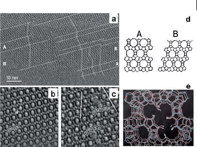
A HRTEM investigation of zeolite - β gave a reasonable explanation [67] . Figure
10.16 a is a HRTEM image of zeolite - β . The basic pore structure contains large
pores, each surrounded by a group of small pores (Figure 10.16 b). There are two
polytypes, A and B, with different modes of stacking (Figure 10.16 d). These two
polytypes can intergrow together, forming many layered defects in a disordered
manner. It was found that the two stacking variants can grow in the same layer
from different sites and are unable to connect each other at the boundary, leading
to the formation of larger pore defects as shown in Figure 10.16 c and e. In the
defective large pores, open bonds are created, which serve as the sites for accom-
modating silanol groups [67] . The observation of these defects by HRTEM also
shed light on the crystallization mechanism of zeolite - β .
Zeolites are crystalline oxides. However, HRTEM imaging of these materials
usually suffers from some diffi culties. Although unit cells of zeolites are large, the
10.7 Porous Materials 469
Figure 10.16 (a) HRTEM of an edge of a
zeolite β crystallite, annotated to show the
stacking directions in different parts.
Nanodomains related to polytypes A and B
are indicated. Defects are visible in the center
of the image, where domains with different
stacking directions meet; (b) Fourier - averaged
image of a domain of type B, with structural
units outlined; (c) Image of two double pore
defects, showing different stacking directions
and outlining secondary structural details on
either side of the defects; (d) Models of the
polytypes A (tetragonal) and B (monoclinic);
(e) Model of the observed defects, obtained
by stacking in the two ways onto a single layer
and continuing to the third similar layer.

470 10 Transmission Electron Microscopy
separations of atomic planes in zeolites are very small (see Figure 10.16 d). It is
impossible to observe the atomic fringes that we often see from normal non -
porous metal oxide crystals. The image contrast patterns of zeolites only show the
pore networks. The second diffi culty is that many zeolites, especially those contain-
ing Al, are beam sensitive. The specimen should be dried before being inserted
into the microscope column. The application of charge - coupled device s ( CCD )
allows signifi cant reduction in the exposure time to the electron beam, thus reduc-
ing specimen damage, since CCDs are much more sensitive to electrons than
photographic detectors [68] . The third diffi culty is low image contrast because the
elements in zeolite frameworks are normally Al, Si and O, without any heavy
metals. Using a small objective aperture may increase the contrast. When a zeolite
contains heavy metal cations, image contrast can be signifi cantly improved [69] .
10.7.2
Mesoporous Silica
Since Mobil scientists reported their synthesis of the M41S series materials in
1992 [70] , tremendous progress has been made in the synthesis of new mesopo-
rous phases and in potential applications of these materials. Unlike crystalline
zeolites, the frameworks of these materials are amorphous. The so - called ordered
mesoporous silicas normally refer only the ordering of the mesopores. Strictly
speaking, they are not “ crystals, ” which must have short - range ordering, although
the term “ crystal ” is still used for these materials in many relevant papers because
no better term is available. The unit cell dimensions of the mesoporous silicas are
much larger than those of the microporous zeolites, and the X - ray powder diffrac-
tion method often gives insuffi cient refl ection peaks. TEM therefore becomes the
most powerful technique for structural characterization of these materials [65,
71 – 74] , although a complete solution of the structures relies on a combination
of various techniques such as XRD, TEM, NMR, gas adsorption – desorption and
so on.
TEM images of mesoporous silica can only show the pore arrangement on a
nanometer scale. Therefore, a low magnifi cation is suffi cient and the multiple
scattering problem in HRTEM at high magnifi cations becomes insignifi cant.
When the pores are large enough, the mass – thickness contrast dominates in the
formation of TEM images and the explanation of the images is relatively easy,
especially when the shapes of pores are simple, for example cylindrical pores in
MCM - 41 [75] and SBA - 15 [76, 77] and spherical pores in SBA - 2 [60, 78] , SBA - 12
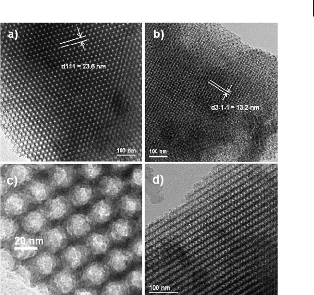
[76] , SBA - 16 [77] , FDU - 12 [79, 80] and so on. Figure 10.17 shows TEM images of
FDU - 12 with a pore diameter of about 20 nm. The face centered cubic structure
of the pores can be determined. The pore size can be directly estimated from the
image of an edge of a particle (Figure 10.17 c).
From other techniques (e.g. gas adsorption/desorption), it is known that the
spherical pores in these mesoporous silicas are connected by some small channels.
A similar property has been found in SBA - 15 in which the straight cylindrical
pores are connected by randomly located small channels. TEM cannot show these
channels directly owing to their extremely low contrast. One possible way to reveal
these channels is to fi ll the pores with a heavy metal. The morphology of the as -
produced metal nanoparticles is the negative replica of the pores in mesoporous
silica [79] . TEM images of the metal nanoparticles show that some of these
nanoparticles are connected by small bridges, which refl ect the small channels in
the original mesoporous silica.
Another group of mesoporous silicas, such as MCM - 48 and KIT - 6, have much
more complicated pore structures. The elucidation of these pore structures is not
straightforward. MCM - 48 is one of the fi rst reported mesoporous phases [70] . Its
structure can be described using a gyroid minimal surface model, fi rst suggested
in 1993 [81] , and confi rmed a few years later using HRTEM [82, 83] and by newly
developed electron crystallography [71] . This minimal surface divides space into
two identical but separate compartments, forming a cubic unit cell containing
bicontinous pores with space group Ia - 3d. This is probably the best example to
demonstrate the successful application of HRTEM in the fi eld of structural chem-
istry of mesoporous silicas.
10.7 Porous Materials 471
Figure 10.17 TEM images of mesoporous silica FDU - 12
viewed down the (a) [110] and (b) [233] directions.
(c) Enlarged TEM image of an edge area of (a). (d) TEM
image of FDU - 12 viewed down the [112] direction.

472 10 Transmission Electron Microscopy
Unlike zeolites, pure silica materials have no acidic sites and are of limited use
for catalysis and other applications. In order to produce acidic mesostructured
materials, aluminum has been successfully introduced into the framework of the
mesoporous MCM - 41 and can be detected by EDX. However, TEM indicated that
the degree of order of the mesopores in MCM - 41 was signifi cantly reduced by
incorporation of even a small percentage of Al into the wall [84] .
Incorporation of many other cations into MCM - 41 to form porous mixed oxides
has been investigated extensively. The guest elements include Ti [85] , V [86] , Ga
[87] , Mn [88] , Fe [89] and Sn [90] . The doped materials often have a lower degree
of ordering compared with the undoped parent MCM - 41 silica.
Another method for creating active sites in MCM - 41 is introducing catalytically
active metal clusters on the inner surface of the pores. If the metal particles are
very small, for example in the form of individual atoms, and are evenly distributed
in the pores, HRTEM may not give enough image contrast. But the presence of
the metal can be confi rmed by EDX elemental mapping. When larger clusters
( > 1 nm) form, they can be detected by HRTEM. It has been shown that direct
images can easily differentiate between clusters inside the pores and on the outer
surface of the mesoporous MCM - 41 [91] . In the case of Ag
3
Ru
10
anchored on the
inner surface of the pores, the clusters can be imaged as some dark dots even
though they are not ordered [92] . Ordered or partially ordered metal clusters inside
the mesopores result in a formation of the so - called rosary pattern of image con-
trast [93, 94] . In this case, an average distance of the cluster separation can be
estimated. The incorporation of metals inside the MCM - 41 pores usually has no
signifi cant effect on the original silica framework. Recently, the clusters inside the
mesoporous materials have been better elucidated by electron tomography, a very
powerful 3D technique developed by Midgley and coworkers [95, 96] .
10.7.3
Porous Oxides
Mesoporous silicas are synthesized using some surfactants as soft templates. If
mesoporous silicas are used as hard templates and crystal growth of metal oxides
is allowed inside the pores, the pore system can be regarded as a nanoreactor. By
removal of the silica template, many porous single crystals of metal oxides have
been fabricated. The fi rst such single crystal oxide, Cr
2
O
3
templated by SBA - 15,
was reported in 2003 [97] . Figure 10.18 a is a low - magnifi cation TEM image from
this specimen. The morphology and size of the particle seems to be the same as
those of the SBA - 15 template. Two sets of SAED patterns can be obtained simul-
taneously from the same particle, showing the single crystal nature of rhombohe-
dral Cr
2
O
3
(left inset of Figure 10.18 a) as well as the ordering of the mesostructure
(right inset, Figure 10.18 a). With higher magnifi cation, TEM images reveal that
the particles consist of an array of hexagonally arranged nanorods (Figure 10.18 b).
Further increasing magnifi cation allows us to view some small bridges connecting
the nanorods (Figure 10.18 c). The diameter of the nanorods is ca 8 nm and the
hollow space between the nanorods is visible as white fringes. HRTEM images
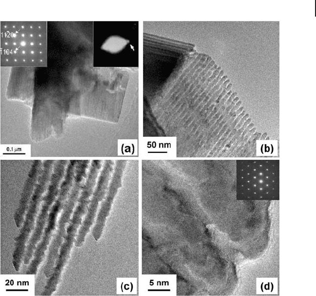
further corroborate the single crystal property of the specimen as shown in Figure
10.18 d. Any nanorod in a particle is part of the same crystal even when the nano-
rods are separated by a nanoscale space. It is assumed that the whole original
mesopore structure in SBA - 15 has been replicated by Cr
2
O
3
crystals.
Several synthetic methods have been developed and various transition metal
oxides, such as Cr
2
O
3
[97, 98] , WO
3
[99] , Co
3
O
4
[100] , Fe
2
O
3
[101] , In
2
O
3
[102] and
others, have been produced as porous single crystals. Most of them are known to
be catalysts. The general route for producing porous crystals of oxides using meso-
porous silica as template is by introducing a metal - containing precursor into the
silica pores and allowing the precursor to decompose, followed by crystal growth
of metal oxides inside the pores during a thermal treatment. Therefore, a crucial
step in the above process is the impregnation of the precursor. Five methods of
10.7 Porous Materials 473
Figure 10.18 TEM and HRTEM images of
porous crystals of Cr
2
O
3
templated by SBA - 15.
(a) Low magnifi cation image showing particle
morphology. The insets are SAED patterns
corresponding to the crystal structure of Cr
2
O
3
(left) and the one - dimensional ordered porous
structure (right); (b) TEM image at a higher
magnifi cation showing a group of parallel
nanorods; (c) TEM image with further
increasing magnifi cation showing small
bridges between the nanorods; (d) HRTEM
image showing perfectly oriented crystal
structure in the nanorods. The inset is the
corresponding SAED pattern from
multi - nanorods.
474 10 Transmission Electron Microscopy
impregnation have been previously developed: the so - called surface functionaliza-
tion method [97, 99] , the dual solvent method [98, 103] , the evaporation method
[100, 104, 105] , the one - step nanocasting method [102] and the most recently
reported solid – liquid method [106 – 108] , respectively. The most popular templates
used are SBA - 15, KIT - 6 and FDU - 12.
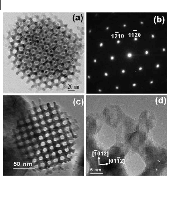
When KIT - 6 is used as a template, the typical morphology of the porous crystals
is spherical as shown in Figure 10.19 a and c and the particle size ( ∼ 300 nm) is
much smaller than the size of KIT - 6 particles (from several microns to tens of
microns). The reason for this phenomenon is a relatively low loading level
of chromium nitrate and a large shrink effect of the phase transformation of the
Cr - containing compounds [98] .
The most unusual feature of Figure 10.19 is that the crystal orientation has a
very close relation with the mesopore structure. For example, when one looks
Figure 10.19 TEM examination of porous
single - crystal of KIT - 6 templated Cr
2
O
3
viewed
down two principal zone axes. (a) TEM image
showing mesopore structure along the [111]
direction of the KIT - 6 related cubic unit cell
and (b) the corresponding SAED pattern
indexed to the rhombohedral unit cell of
crystalline Cr
2
O
3
. (c) TEM image showing the
mesopore structure along the [100] zone axis
of the KIT - 6 related unit cell and (d) the
corresponding HRTEM image on the
221
[]
zone axis of Cr
2
O
3
unit cell.

down the [111] zone axis of the KIT - 6 templated mesopore structure (Figure
10.19 a), seeing a hexagonal pattern of the pores, a hexagonal pattern of SAED
corresponding to the [001] zone axis of the rhombohedral Cr
2
O
3
can be obtained
without specimen tilting (Figure 10.19 b). Consequently, the [111] axis of the KIT -
6 - like cubic mesoporous unit cell and the [001] axis of Cr
2
O
3
are perfectly parallel.
When a particle is imaged on the [100] projection of the cubic mesoporous system
(Figure 10.19 c), a perfect square pattern of the mesopores can be seen. Figure
10.19 d is the corresponding HRTEM image recorded from a corner of the particle
in Figure 10.19 c. The image viewed down the
221
[]
axis of Cr
2
O
3
shows a contrast
pattern which is the closest to a square pattern from the Cr
2
O
3
crystal structure.
From this sample, many particles have these peculiar orientations, which seem to
have a close relation with the structural symmetry of KIT - 6. This unique phenom-
enon has not been observed with other samples of porous oxides. At present, the
reason for the formation of such coherence between crystal structure and the
symmetry of the nanopore system is not understood.
If we compare the image contrast pattern in Figure 10.19 c with the correspond-
ing one from KIT - 6, we can conclude that Cr
2
O
3
only replicated one of two inter-
laced pores in KIT - 6. Figure 10.19 a is a rare example showing replication of both
pores in the central area. On the other hand, TEM images from KIT - 6 - templated
Co
3
O
4
showed that two interlaced pores were replicated in all the particles [100] .
Pore size and pore volume measurements by N
2
adsorption/desorption of these
two specimens confi rmed the above conclusion. This implies that there are some
small channels connecting the two interlaced pores in KIT - 6.
Crystal growth of metal oxides has also been performed in the pore systems of
some cage - containing mesoporous silicas, such as FDU - 12 [79, 80] and SBA - 16
[77] . SBA - 16 has a body centered cubic structure (space group
Im
m
3
) and FDU - 12
is face centered cubic (space group
Fm m3 ). Accordingly, each spherical nanocage
is 8 coordinated by the neighboring nanocages in SBA - 16, but 12 coordinated in
FDU - 12. When crystals of oxides form in these two silica phases, it can be expected
that the structures of the products are 3D arrangements of solid nanospheres
connected to each other by some very short nanorods [107, 109] . The HRTEM
technique has been used to examine the yields and the single crystal properties of
these porous oxides. The small bridges are barely revealed in the TEM images.
However, it is possible to see a bridge at an edge of a particle where two adjacent
nanospheres can be identifi ed. Another diffi culty in imaging the porous crystals
templated by these mesoporous silicas is that, since the crystal orientation has no
relation to the mesostructure, it is diffi cult to fi nd a view direction parallel with
principal axes of both the crystal structure and the mesopore structure.
It seems to be possible that most transition metal oxides can be made in porous
crystals with different morphologies using various mesoporous silicas as tem-
plates. It is expected that these materials have potential in applications such as
catalysis, fuel cell, gas sensors and Li - batteries. Their physical properties would
fall in between nanoparticles and bulk specimens, although our knowledge about
these properties is still very limited.
10.7 Porous Materials 475

476 10 Transmission Electron Microscopy
10.8
Low - Dimensional Oxide Crystals
It has been well known that HRTEM is a powerful tool to investigate structures
of low - dimensional oxides, such as nanoparticles, nanowires, nanorods and nano-
tubes, while the information from powder diffraction of these low - dimensional
materials is normally very limited merely because their small crystallite sizes. For
the nanoscale oxides, HRTEM can give useful information on particle size, crystal
structure, particle morphology, structural defects and possible inter - particle
connections.
10.8.1
Nanoparticles
An important type of nanoscale oxide is the so - called quantum dot ( QD ) which
has size - dependent photoemission properties. Fu and coworkers have reported an
aqueous dispersion of ZnO QDs with strong blue emission (quantum yield of
76%). HRTEM images directly show the particle size of about 5 nm or below and
quite narrow size distributions [110] .
Nanoscale core – shell structures are also of great interest. When Zn/ZnO core –
shell nanoparticles are imaged by TEM at a low magnifi cation, the image contrasts
from the core and the shell may be signifi cantly different due to a difference of
the mass – thickness (or density of Zn cations) between these two components
[111] . The structures of the core and shell are also different, leading to a large dif-
fraction contrast as well. Consequently, the thickness of the ZnO shells can be
measured directly from the images. The information helps in the refi nement of
the synthetic conditions and allows the dimensions of nanoparticles to be control-
lable. HRTEM images can further reveal the crystal structures of ZnO in the shell.
As observed by Zeng and coworkers, the ZnO shells are polycrystalline [111] .
The overall properties of nanoparticle materials depend not only on their struc-
tures but also on their size. It is therefore crucial to have a narrow particle size
distribution for some applications. Since TEM often shows individual particles, it
is necessary to examine a large number of particles for a reasonably good estima-
tion of particle size distribution. A good example was shown by Park and cowork-
ers, who observed almost uniform sizes of spherical nanocrystals of MnO, CoO,
Fe
3
O
4
(magnetite) and Fe
2
O
3
(maghemite) from large areas of the specimens [112] .
Fe/Fe
3
O
4
core – shell nanotubes were imaged by HRTEM by Shavel and coworkers
[113] . The crystal structures of the iron core and the Fe
3
O
4
shell can be clearly
identifi ed.
Magnetic nano - γ - Fe
2
O
3
is a useful material in nanodevices as it allows separation
of nanomaterials in a magnetic fi eld. For example, Pang and coworkers simul-
taneously embedded fl uorescent CdSe/ZnS QDs and magnetic nano - γ - Fe
2
O
3
into hydrazinized styrene/acrylamide (H
2
N - St - AAm) copolymer nanospheres to
produce cell - targeting multifunctional nanospheres [114] . Figure 10.20 shows a
typical spherical polymer particle of the specimen with QDs and Fe
2
O
3
nanoparti-
