Jackson Mark. Machining with Abrasives
Подождите немного. Документ загружается.

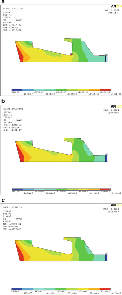
Fig. 3.12 Maximum stress (circumferential) in the electroplated cBN grinding wheel rotating at
200 m/s: ( a) aluminum alloy center; (b) carbon fiber center; and (c) steel center. Stress scale is in
N/mm. Used with permission from Inderscience Publishers (2010)
3 Grinding Wheel Safety and Design 145
3.8 Recessed Grinding Wheels
3.8.1 Small Cup Recessed Grinding Wheels
Grinding wheels that are subjected to high rotational stresses can eventually “burst”
by breaking into smaller fragments that are dominated by bending moments at the
onset of fracture. This causes damage to the grinding machine and to the operator if
guards inadequately prevent the fragments from penetrating the case of the machine
tool. It is of prime importance to be able to calculate the bursting speed of the
grinding wheel accurately in order to prevent this from occurring. The energy
contained within a fragment of grinding wheel spinning at a certain speed was
calculated by Jackson et al. [10]. Methods used to calculate bursting speed that are
based on the bending strength of the vitrified material are not accurate and deviate
from the true bursting speeds of rotating grinding wheels. Deviations of up to 20%
have been observed by Munnich [11]. Table 3.1 shows the deviations for a variety
of grinding wheels with constant bonding formulation, but different abrasive mesh
sizes. The grinding wheel was a parallel-sided vitrified wheel with an outer dia-
meter, D, of 610 mm, inner diameter, H, of 304.8 mm, and a thickness, T, of 20 mm.
Thies [12] and Pompe et al. [13] considered the use of fracture mechanics
coupled with the stochastic nature of vitrified compositions to improve the calcula-
tion of bursting speed, but unfortunately did not provide any improvement in
accuracy. Mewes et al. [14] developed correction functions using linear regression
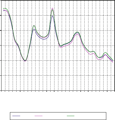
Stress Factor Vs Node Numbers (V=200 m/s)
0
0.1
0.2
0.3
0.4
0.5
0.6
2
17
22
20
25
34
41
48
60
73
83
86
104
116
119
Node Numbers
Stress Factor
Steel Aluminium Carbon Fibre
Fig. 3.13 Stress factor at various nodal positions on the cross-section of the electroplated cBN
grinding wheel rotating at 200 m/s. Used with permission from Inderscience Publishers (2010)
146 M.J. Jackson
techniques, but they are not applicable because of non-uniform deviation of the
calculated bursting speed compared to observed bursting speeds. In a recent paper
by Behrens and Kammler [15], a procedure is described where bursting speed is
calculated using linear elastic fracture mechanics coupled with the determination of
rotational stresses using finite element calculations. In their approach, the critical
pore size that trigge rs failure is calculated for a 36-mesh and an 80-mesh vitrified
grinding wheel. The stress intensity at the flaw tip is calculated using the mode I
stress intensity factor, and is used to calculate the fracture toughness of the abrasive
body. The experimental fracture toughness is measured using a single edge v-notch
beam loaded in the four-point bending mode to failure. Th e results are then used in
concert with a set of modifying functions that are incorporated into Munnich’s
equation for calculating bursting speed. The modified equation is:
v
bursting
¼
ffiffiffiffiffiffiffiffiffiffiffiffiffiffiffiffiffiffiffiffiffiffiffiffiffiffiffiffiffiffiffiffiffiffiffiffiffiffiffiffiffiffiffiffiffiffi
4s
fracture
3 þ n þð1 nÞ:
H
2
D
2
:r:f
s
s
(3.17)
0
10
20
30
40
50
60
70
120 140 160 180 200 220 240
Grindin
g
wheel surface s
p
eed
(
m/s
)
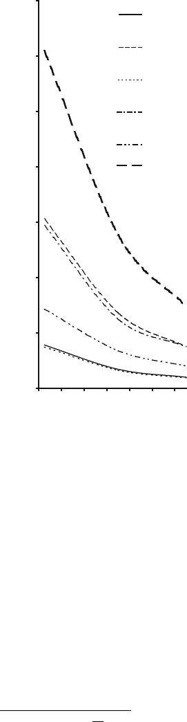
Safety factor
Hyperbolic solid disc:
Steel
Hyperbolic solid disc :
Carbon Fibre
Trapezoidal solid disc :
Steel
Trapezoidal solid disc :
Carbon Fibre
Porous disc : Steel
Porous disc : Carbon
Fibre
Fig. 3.14 Effect of material
and geometric shape of the
reinforcing center-section on
the safety factor of vitrified,
segmented grinding wheels.
Used with permission from
Inderscience Publishers
(2010)
3 Grinding Wheel Safety and Design 147
where v
bursting
is the bursting speed, s
fracture
is the fracture strength of the grinding
wheel, n is Poisson’s ratio, H is diameter of the bore of the grinding wheel, D is the
outer diameter of the grinding wheel, r is the density of the vitrified material, and f
s
is the stress intensity function at the maximum tangential stress at the outer edge of
the bore as a function of the normalized diameter and the depth of the recess. The
function f
s
is calculated using the following equation:
f
s
¼3: 00102x
3
þ 4:49064x
2
2:58489x þ0:640967y
2
2:05676y
þ 4:98248x
3
y
3
8:56909x
2
y
2
þ 6:31512xy þ 1:59627
(3.18)
where x ¼P/D, y ¼F/T, P is the diameter of the recess, T is the thickness of the
grinding wheel, F is the depth of the recess, x is the normalized recess diameter, and
y is the normalized recess depth. Equations (3.17) and (3.19 ) are valid for the range
of F/T between 0.13 and 0.88, and for the range of P/D between 0.36 and 0.96.
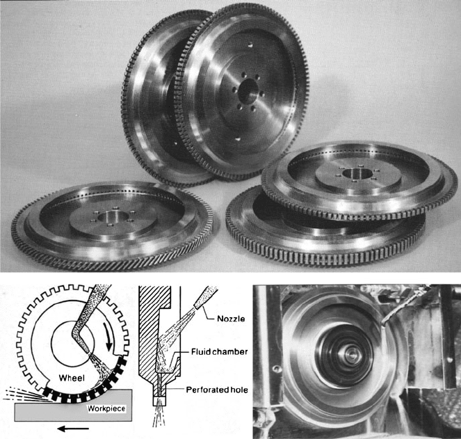
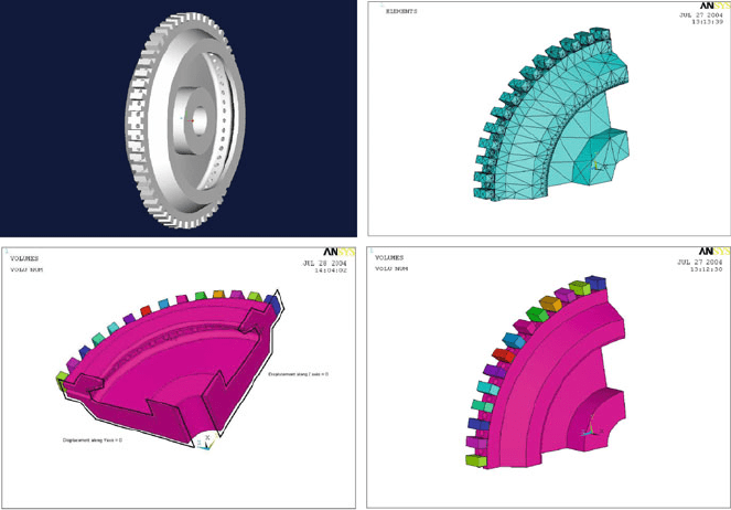
Fig. 3.15 Slotted grinding wheels showing mechanism of lubricant penetration (courtesy of
Dr. M. W. Bailey, De Beers Diamond Company)
148 M.J. Jackson
Equations (3.17) and (3.18) are used in the present work for calculating bursting
speeds for a variety of different recessed grinding wheels and are compared with
experimental bursting speed data.
3.8.1.1 Computational Analysis
Dynamic loads on a rotating grindin g wheel is defined in the rotating co-ordinate
system and while the stiffness and damping terms are the same as those measured in
the stationary system, the terms due to inertial resistance are dependent upon the
rotation of the grinding wheel. Owing to the porous nature of the grinding wheel
body, the dynamic imbalance is magnified in certain parts of the grinding wheel
when rotating at certain speeds. The inertial depend ent terms need to be determined
for a particular wheel structure and are then added to the total impedance of the
structure before static and dynamic analyses in the rotating wheel can be performed.
The approach in this study assumes that the co-ordinate system used will rotate
at a constant rate about a fixed axis. Displacements associated with the structure and
forces applied to the structure are measured in the rotating system. The system is
accelerating relative to a stationary inertial system and as such, the mass dependent
impedance cannot be directly calculated in the rotating system. Therefore, the
impedance is calculated for the stationary system then transformed to the rotating
Fig. 3.16 Finite element model of a slotted grinding wheel showing boundary conditions and
elements in various orientations. The images show the inclusion of coolant holes in the body of the
wheel that are used to direct coolant into the slots that separate the abrasive segments. Used with
permission from Inderscience Publishers (2010)
3 Grinding Wheel Safety and Design 149
system. The development of general transformations is required between stationary
and rotating systems. This is accomplished by describing the general vector trans-
formations between stationary and rotating systems, defining the inertial terms in
the rotating co-ordinate system, applying these results to develop impedance in the
rotating system, and finally, the gyroscopic terms are added to the structural
matrices for analyzing the rotating system.
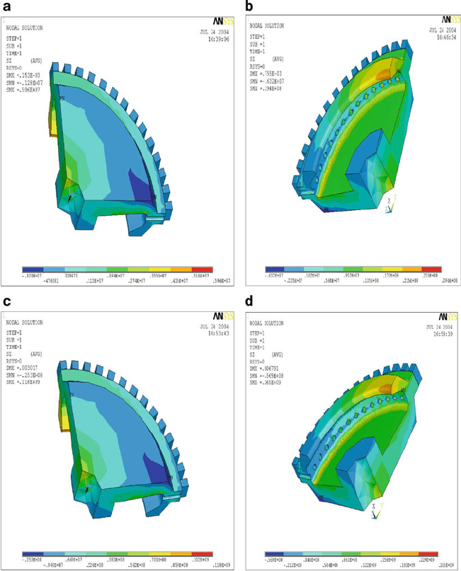
Fig. 3.17 Finite element hoop stress plots showing an aluminum body in various configurations at
maximum peripheral operating speed of (a) 45, (b) 100, (c) 200, and (d) 300 m/s. Used with
permission from Inderscience Publishers (2010)
150 M.J. Jackson
The general transformation of a time-dependent vector from a stationary to a
rotating co-ordinate is given by the following:
vðtÞ
r
¼ AðtÞ½vðtÞ
s
(3.19)
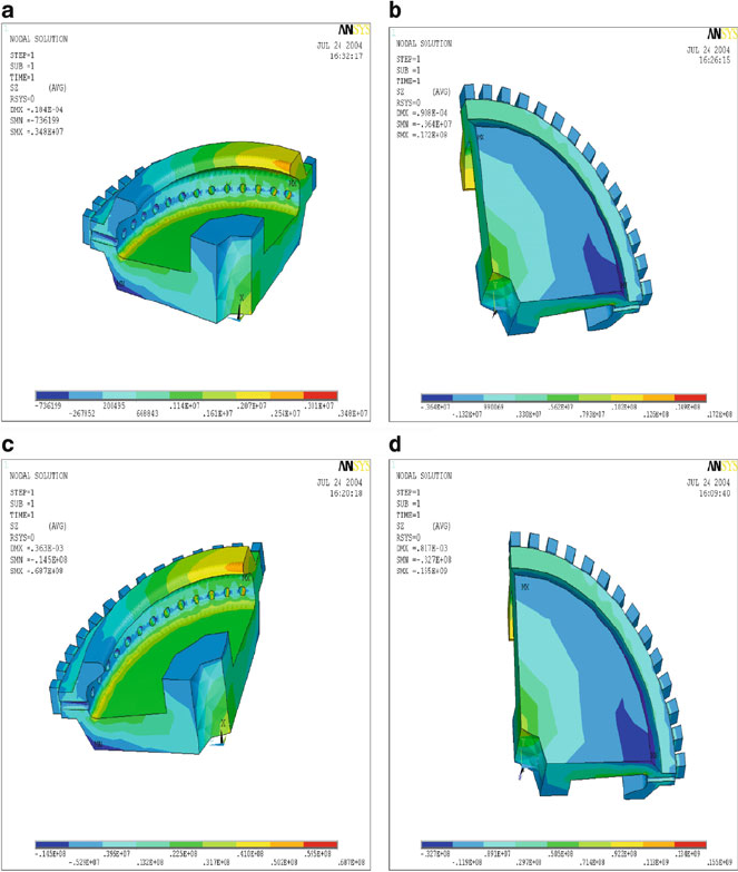
Fig. 3.18 Finite element hoop stress plots showing a carbon fiber body in various configurations
at maximum peripheral operating speed of (a) 45, (b) 100, (c) 200, and (d) 300 m/s. Used with
permission from Inderscience Publishers (2010)
3 Grinding Wheel Safety and Design 151
where {v(t)
r
} is the rotating co-ordi nate system of the time-dependent vector, [A(t)]
is the time-dependent transformation matrix from the rotating to the stationary
system, and {v(t)
s
} is the stationary co-ordinate system of the time-dependent
vector. The transformation is valid for any vector, both real and complex. Trans-
formations using complex identities for small angular deviations allows the
transformation vector to be described in the x-y-z co-ordinates:
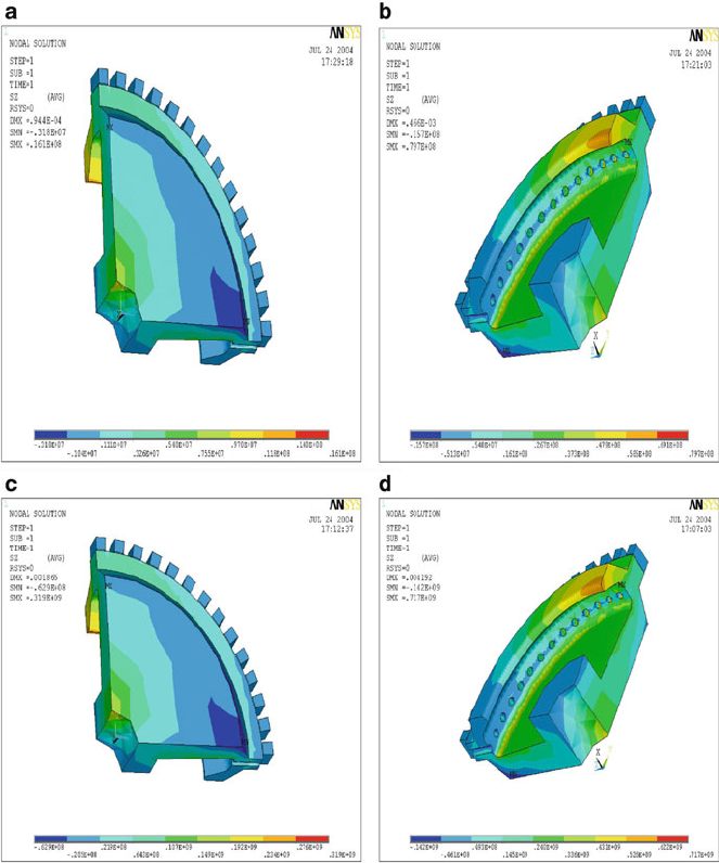
Fig. 3.19 Finite element hoop stress plots showing a steel body in various configurations at
maximum peripheral operating speed of (a) 45, (b) 100, (c) 200, and (d) 300 m/s. Used with
permission from Inderscience Publishers (2010)
152 M.J. Jackson
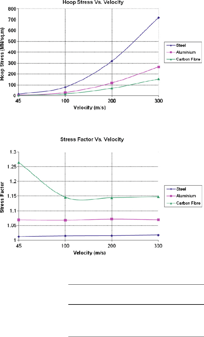
Fig. 3.20 Calculated hoop stress versus peripheral velocity for the various types of slotted
grinding wheels. Used with permission from Inderscience Publishers (2010)
Fig. 3.21 Stress factor versus peripheral velocity for various types of slotted grinding wheels.
Used with permission from Inderscience Publishers (2010)
Table 3.1 Calculated and
measured bursting speeds
of a parallel-sided vitrified
grinding wheel
Abrasive
mesh size
Calculated bursting
speed (m/s)
(Munnich [ 11])
Measured
bursting
speed (m/s)
36 140.7 119.6
54 156.5 133
70 166.9 142.8
100 183.8 153.9
150 196.9 164.6
3 Grinding Wheel Safety and Design 153

xðtÞ
r
yðtÞ
r
zðtÞ
r
8
>
<
>
:
9
>
=
>
;
¼
e
iy
2
1 i 0
i 10
000
2
4
3
5
þ
e
iy
2
1 i 0
i 10
000
2
4
3
5
þ
000
000
001
2
4
3
5
0
@
1
A
xðtÞ
s
yðtÞ
s
zðtÞ
s
8
>
<
>
:
9
>
=
>
;
(3.20)
Or,
xðtÞ
r
yðtÞ
r
zðtÞ
r
8
>
<
>
:
9
>
=
>
;
¼
e
iy
2
T
1
½þ
e
iy
2
T
1
½
þ T
o
½
xðtÞ
s
yðtÞ
s
zðtÞ
s
8
>
<
>
:
9
>
=
>
;
(3.21)
And the conjugate matrix is:
½T
1
¼
1
2
1 i 0
i 10
000
2
4
3
5
(3.22)
½T
1
¼
1
2
1 i 0
i 10
000
2
4
3
5
(3.23)
½T
o
¼
000
000
001
2
4
3
5
(3.24)
Equation (3.21) can be re-formulated as a transformation from rotating to non-
rotating co-ordinates where the progressive and regress ive vectors can be written in
terms of a non-rotating system, thus,
xðtÞ
s
yðtÞ
s
zðtÞ
s
8
>
<
>
:
9
>
=
>
;
¼
e
iy
2
T
1
½
þ
e
iy
2
T
1
½þT
o
½
xðtÞ
r
yðtÞ
r
zðtÞ
r
8
>
<
>
:
9
>
=
>
;
(3.25)
Inertial forces are cal culated using Newton’s laws of motion, whilst particles
contained within the body are defined as position vectors. The inertial force on a
particle whose position is measured relative to a rotating co-ordinate system is,
154 M.J. Jackson