Hoque. Advanced Applications of Rapid Prototyping Technology in Modern Engineering
Подождите немного. Документ загружается.

Rapid Prototyping for Evaluating
Vehicular Communications 5
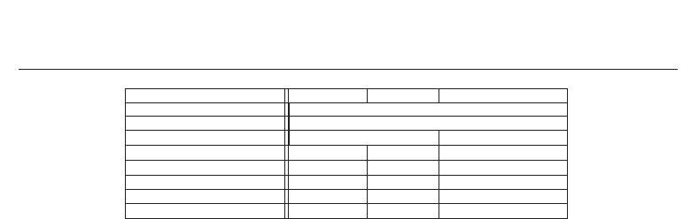
Parameter 802.11p 802.11a 802.16e
Carrier Modulation BPSK, QPSK, 16-QAM, 64-QAM
Code rate 1/2, 2/3, 3/4
# subcarriers 48 data + 4 pilots 360 data + 60 pilots
OFDM symbol duration 8 μs 4 μs 64 μs
Guard time 1.6 μs 0.8 μs 12.8 μs
FFT period 6.4 μs 3.2 μs 51.2 μs
Total bandwidth 10 MHz 20 MHz 10 MHz
Subcarrier spacing 156.25 KHz 312.5 KHz 19.53 KHz
Table 1. Feature comparison of wireless standards.
limited to the minimum (to obtain the channel model, if there is none already available) and
the rest of the experiments are carried out inside a testing lab.
There are many commercial channel emulators that are manufactured by companies such
as Spirent, Rhode & Schwarz, Azimuth Systems, Agilent... These emulators are usually
general-purposed (for instance, Spirent’s SR5500 or Rhode’s AMU200A), but there are some
that are aimed at evaluating a specific technology, like Azimuth’s 400WB MIMO Channel
Emulator (for IEEE 802.11n and Mobile WiMAX MIMO systems) or Agilent’s N5106A PXB
MIMO Receiver Tester (with built-in LTE and Mobile WiMAX channels).
All these channel emulators are robust and work great for most applications, but they are
normally quite expensive and may not offer enough flexibility to researchers when setting
channel configuration parameters. To tackle these issues a number of low-cost ad-hoc channel
emulators have recently been proposed.
Due to real-time constraints and suitability, most of the proposed low-cost,
easily-reconfigurable ad-hoc emulators are based on FPGA technology. Some examples
are described in (Alimohammad, 2008; Ghazel, 2003; Hwang, 2007). In (Ghazel, 2003) an
FPGA-based AWGN channel emulator is implemented. The emulator is based on a hardware
white Gaussian noise generator that is developed by combining the Box-Muller and Central
limit theorems, and designing the whole model in VHDL (Very High Speed Integrated Circuit
Hardware Description Language). Similarly, in (Alimohammad, 2008), the authors use a
Xilinx Virtex-II Pro to implement a fading channel emulator. The fading process models
use sum-of-sinusoids (SOS) algorithms that allow designing and implementing Rician and
Rayleigh fading channels.
Finally, (Hwang, 2007) presents a baseband multipath fading channel emulator implemented
on a Virtex-IV using the Xilinx XtremeDSP FPGA platform. The emulator is implemented
using Simulink models and System Generator IP blocks. The final design is limited to a
two-path channel due to the extensive use of FPGA resources; the input/output rate is set
to 20 MHz; and the Doppler frequency is 5 Hz.
The above mentioned developments have at least two major drawbacks. First, the use of
low-level description languages such as VHDL results in slow development stages. Although
in most cases VHDL allows obtaining a resource-efficient FPGA design, programming can
become a cumbersome task that may consume a large amount of time and economic resources.
There are new sophisticated tools like System Generator which allow working with high-level
blocks to build complex designs easier and faster.
The second problem is related to the use of high-level tools. These tools facilitate fast
prototyping but they usually generate non-optimized large designs that may not fit into
the FPGA. For instance, in (Hwang, 2007) the authors only download a two-path channel
emulator due to the lack of available hardware resources. Hence, for large designs,
optimizations must be made.
The vehicular emulator described in this chapter addresses these issues: we used System
Generator to develop the channel emulator faster than using VHDL and we optimized our
271
Rapid Prototyping for Evaluating Vehicular Communications

6 Will-be-set-by-IN-TECH
design in order to be able to implement a twelve-path channel emulator, leaving space for
future extensions, such as MIMO emulation, also described herein in Section 4.
3.1 Implemented vehicular channel models
The implemented channel models are based on the excellent work in (Acosta, 2007b) and
(Acosta, 2007a), that is mainly based on a measurement campaign at 5.9 GHz carried out
in the spring of 2006 in Atlanta, Georgia. From these measurements the authors obtained
six different channel models that cover the most common situations where VTV and RTV
communications may take place:
• Urban canyons, with dense and tall buildings, where vehicles move at speeds between
32 Km/h and 48 Km/h.
• Suburban expressways, with moderately dense, low-story buildings, where the
measurement speed was approximately 105 Km/h.
• Suburban surface streets, with moderately dense, low-story buildings, where the driving
speed was between 32 Km/h and 48 Km/h.
Although the measurement campaign was performed at 105 Km/h in expressways and
32 Km/h to 48 Km/h for surface streets, the authors scaled the models to make their Doppler
frequencies consistent with vehicle speeds of 140 Km/h and 120 Km/h, respectively.
Vehicular Channel Distance Speed Path Modulation Maximum Rician K Overall Maximum Maximum LOS
TX-RX (km/h) (number of paths) Delay Spread (dB) K Factor Freq. Shift Fading Doppler Doppler
(m) (ns) (dB) (Hz) (Hz) (Hz)
VTV-Expressway Oncoming 300-400 140 Rician (1) / Rayleigh (10) 302 -1.6 -3.6 1466 858 1452
RTV-Urban Canyon 100 120 Rician (1) / Rayleigh (11) 501 7.5 6.7 720 994 654
RTV-Expressway 300-400 140 Rician (1) / Rayleigh (11) 401 -5.3 4.3 769 813 770
VTV-Urban Canyon Oncoming 100 120 Rician (1) / Rayleigh (11) 401 4.0 3.0 1145 936 1263
RTV-Suburban Street 100 120 Rician (1) / Rayleigh (11) 700 3.3 2.1 648 851 635
VTV-Express. Same Dir. with Wall 300-400 140 Rician (2) / Rayleigh (10) 701 23.8, 5.7 3.3 -561 1572 -60, 40
Table 2. Main characteristics of the vehicular models.
Our channel emulator implements these six vehicular channel models, whose key
characteristics are summarized in Table 2. For each model, the following parameters are
shown: distance between the transmitter and the receiver, speed of the vehicle, number of
paths of the channel and their modulation (Rician or Rayleigh), maximum delay spread,
Rician K for the Rician paths, overall K factor (i.e. the ratio of the deterministic power over
the total random power of all taps), maximum frequency shift for all paths, maximum fading
Doppler (i.e. maximum half-width of the fading spectral shapes of all the paths of each
channel) and LOS Doppler of the Rician paths.
Vehicular Channel Coefficient generation Interpolation Occupied Occupied Occupied Occupied Occupied
rate [Effective rate] (Hz) rate Slices (%) Slice Flip-Flops (%) LUTs (%) FIFO16 / RAMB16s (%) DSP48s (%)
VTV-Expressway Oncoming 3484 [4000] x2500 76% 36% 50% 19% 60%
RTV-Urban Canyon 2194.6 [2500] x4000 84% 39% 57% 20% 65%
RTV-Expressway 2168 [2500] x4000 84% 39% 57% 20% 65%
VTV-Urban Canyon Oncoming 3314 [4000] x2500 84% 39% 57% 20% 65%
RTV-Suburban Street 1988 [2000] x5000 84% 39% 57% 20% 65%
VTV-Express. Same Direction With Wall 3170 [4000] x2500 85% 40% 57% 24% 65%
Table 3. General parameters and resources occupied by the vehicular channel emulator.
Table 2 also gives an idea of the complexity involved in the implementation of these channels.
These high speed and high delay spread scenarios own large Doppler shifts that force the
emulator to interpolate and rapidly update each path coefficients. Moreover, although the
amount of required FPGA hardware is reduced by working with the baseband IQ components
272
Advanced Applications of Rapid Prototyping Technology in Modern Engineering
Rapid Prototyping for Evaluating
Vehicular Communications 7
!
"#
$
$
$
$
$
$
$
$
$
$
$
%&'
%&'!
%&'
%&'!
%&'
%&'!
%&'
%&'!
%&'
%&'!
%&'
%&'!
%&'
%&'!
%&'
%&'!
%&'
%&'!
%&'
%&'!
%&'
%&'!
!'$
(&
$
)%#
*
%&
%&$
%&
%&$
%&
%&$
%&
%&$
%&
%&$
%&
%&$
%&
%&$
%&
%&$
%&
%&$
%&
%&$
%&
%&$
+
+$
$
(&
(,
%
(
(&&%-
!
!
!
!
!
!
!
!
!
!
!
.
&)#
#
%&
%&$
%&
%&$
%&
%&$
%&
%&$
%&
%&$
%&
%&$
%&
%&$
%&
%&$
%&
%&$
%&
%&$
%&
%&$
,'
.
!
-
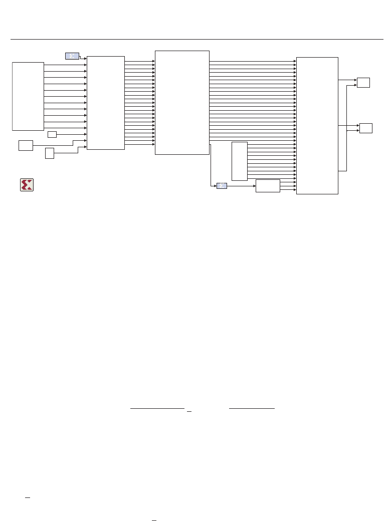
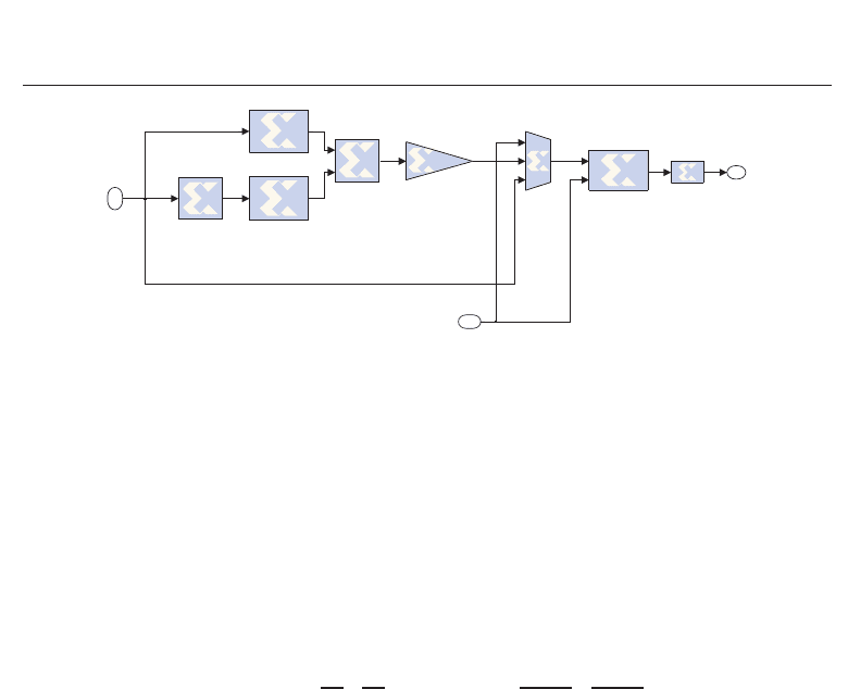
Fig. 2. General view of the System Generator model optimized for the vehicular channel
VTV-Expressway Oncoming.
at 10 MHz, it is not possible to implement the six channels into our FPGA. Thus, six
independent .bit files are generated though, in practice, only three different FPGA designs
are needed due to the model similarities:
• One design is exclusively dedicated to the channel VTV-Expressway Oncoming which is the
only one with eleven paths.
• Another model is used for VTV-Expressway Same Direction with Wall because it requires the
existence of two Rician and ten Rayleigh paths, while the rest of the channels (apart from
VTV-Expressway Oncoming) consists of just one Rician path and eleven Rayleigh paths.
• One design for the other four channels, which differ in their configuration parameters but
share all their FPGA resources.
3.2 Theoretical channel model
For the generation of each channel coefficient at the i-th path in the time instant t, we used the
following model
h
(i, t)=
K
i
P
i
/(K
i
+ 1) h(i, t)+
P
i
/(K
i
+ 1) h
w
(i, t) (1)
where
• K
i
and P
i
are, respectively, the Rice factor and the power of the i-th path.
• h
w
(i, t) represents the contribution of the non-line-of-sight (NLOS) component to the i-th
path at the time instant t. It is a random variable that follows a complex Gaussian
distribution with mean zero and unit variance.
•
h(i, t): contribution of the line-of-sight (LOS) component to the i-th path at the time instant
t. It is determined by
h(i, t)=e
j(2π f
D,i
cos(θ
i
)t+φ
i
)
(2)
where f
D,i
, θ
i
and φ
i
are, respectively, the maximum Doppler spread, angle of arrival and
phase of the LOS component of the i-th path.
273
Rapid Prototyping for Evaluating Vehicular Communications

8 Will-be-set-by-IN-TECH
To decrease the number of input configuration parameters, we calculate off-line several of the
operations involved in (1) and (2). As it can be viewed in Fig. 2, the emulator only needs five
parameter blocks:
• Sigma block contains the power factors of the NLOS components: σ
=
P
i
/(K
i
+ 1).
• A block holds the power factors of the LOS components: A
=
K
i
P
i
/(K
i
+ 1).
• FrequencyLOS block contains part of the exponent of
h(i, t): f
LOS
= 2π f
D,i
cos(θ
i
).
• PhaseLOS block is simply φ
i
.
• Taps delay block holds the normalized delays of the different paths.
3.3 Hardware and software
The vehicular channel emulator is implemented on an FPGA using Nallatech’s BenADDA-IV
development kit which has the following features: it contains a Virtex IV (XC4VSX35-10FF668)
that allows using Xtreme-DSP slices of up to 400 MHz; includes 4 MB of 166MHz ZBT-RAM,
two 14-bit ADCs able to work up to 105 MS/s and two 14-bit DACs that can run up to
160 MS/s; provides a dedicated internal clock up to 105 MHz, although it can use an external
clock; offers the possibility to operate either connected to a PC (via the PCI bus) or in
stand-alone mode.
In order to diminish the amount of time required to implement the channel model on
the FPGA, we decided to use System Generator for DSP because it enables to design and
program our Virtex IV faster. It allows using libraries of high-level blocks and can interact
with MATLAB and Simulink. Moreover, another advantage of this software is its ability to
exchange data between a design running in the FPGA and a software implementation that is
executed on a PC. In fact, for our tests (Section 5) we have run in MATLAB and Simulink the
transceivers that interact with the vehicular emulator, which was running on the FPGA.
3.4 FPGA design overview
Fig. 2 shows a general view of the hardware design. Several blocks represented in such figure
contain sub-blocks which are shown throughout this chapter: the Coefficient Generator
block includes Figs. 3 and 4, the Interpolator block contains a number of interpolators like
the one shown in Fig. 5.
The design depicted in Fig. 2 has been optimized for a specific channel (VTV-Expressway
Oncoming), although the rest of channels models share most of the hardware resources.
The design can be divided into different parts that carry out six different major tasks:
acquisition of the channel parameters, Gaussian noise generation, Doppler filtering, LOS
Doppler generation, interpolation and FIR filtering.
3.4.1 Acquisition of the channel parameters
The generation of the configuration parameters of the vehicular channel is performed offline
since they remain constant throughout the emulation. The parameters are stored into registers
readable by the FPGA. All the parameters equal to zero for a particular channel are removed
to save hardware. For example, all the channels but VTV-Expressway Same Direction With Wall
have one Rician component, so in these channels we only need one register to store each of
the LOS parameters detailed in Section 3.2.
274
Advanced Applications of Rapid Prototyping Technology in Modern Engineering
Rapid Prototyping for Evaluating
Vehicular Communications 9
3.4.2 White gaussian noise generation
To obtain the NLOS coefficients, we need to use the System Generator’s White Gaussian Noise
Generator (WGNG) block that generates i.i.d samples from a Gaussian distribution with zero
mean and unit variance. Since the maximum number of complex paths is twelve, we need to
obtain twenty-four real-valued of such noise samples that will be filtered depending on the
Doppler experienced by each path. Instead of using twenty-four independent WGNG blocks,
we multiplex in time the samples produced by only one WGNG block (Fernández-Caramés,
2010). This optimization is crucial since each WGNG block consumes an important amount
of FPGA resources. Since each WGNG block runs at 10 MHz, using a twenty-five output
multiplexor (twenty-five is the integer divider of 10 MHz closest to twenty-four), leads us to
generate twenty-four noise samples at a frequency of 400 KHz, that still is several orders of
magnitude higher than the desired channel coefficient generation effective rates (see Table 3).
Therefore, the optimization of the 24-output Gaussian noise generator makes the emulator to
produce channel coefficients slower but at a sufficiently high rate, and saving a great deal of
FPGA resources.
Using the System Generator’s Resource Estimator block, there is a 95% of saving for all the
FPGA resources thanks to this optimization (Fernández-Caramés, 2010). Also, if we needed to
reduce the number of occupied resources, it would be possible to avoid using WGNG blocks:
the channel coefficients could be generated in MATLAB and then transferred to the FPGA.
However, there are important drawbacks in this approach:
• If the channel coefficients were only transmitted from MATLAB during the initialization
phase, due to the limited amount of memory on the FPGA, there would be a time when
the channel coefficients would have to be used again. Therefore, correlation in the output
signal would appear.
• If we transfer a new set of channel coefficients from MATLAB at fixed intervals, we would
not be able to use the emulator in stand-alone mode since we always would relay on having
a computer running MATLAB linked to the FPGA.
3.4.3 Doppler filtering
To generate the actual NLOS components, the generated white Gaussian noise samples have
to be filtered according to each path’s Doppler spectrum. This spectrum is determined by a
fading spectral shape, a frequency shift and a maximum Doppler shift. Table 2 shows these
latter two parameters for the considered channel models. Four different spectral shapes are
considered: round, flat, classic 3 dB and classic 6 dB (Acosta, 2007a).
!"
#
$
%
!"
#
$
%
!&
$
%
!&
$
%
!&
$
%
'
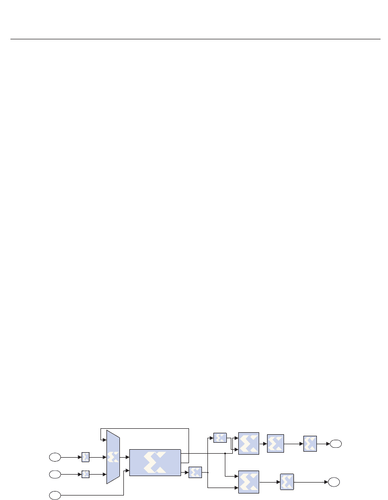
Fig. 3. Optimized blocks for applying the Doppler Spectrum.
Fig. 3 shows the blocks that allow applying the Doppler spectrum to each Rayleigh path. Each
Doppler filter consists of 256 coefficients. This filter size provides a good tradeoff between
precision and hardware complexity. Since each filter is unique for each path of each vehicular
channel, we hard-coded the coefficients in each of the six .bit files.
275
Rapid Prototyping for Evaluating Vehicular Communications
10 Will-be-set-by-IN-TECH
To reduce to a half the required hardware, we exploit the fact that the real and the imaginary
parts of the filter have to be used twice for each path to perform the complex FIR filtering (see
Fig. 4). This optimized block can be seen in Fig. 3, which is contained under the block Doppler
Filter shown in Fig. 4.
Table 4 shows some of the resource savings, achieved when reducing to a half the number of
filters in a vehicular channel with eleven paths. Although the optimized block uses slightly
more slices, the savings occur in the DSP48 and the RAMB16 blocks, that are reduced by 50%.
This is important, since the lack of this type of blocks is a bottleneck to keep on designing the
rest of the emulator.
Resource Optimized Non-optimized Total FPGA Savings
type 24-output Gaussian generator 24-output Gaussian generator resources (%)
Slices 7382 7239 15360 -1.9%
DSP48 blocks 88 176 192 50%
RAMB16 blocks 44 88 192 50%
Table 4. Savings due to the optimization of the Doppler filter block
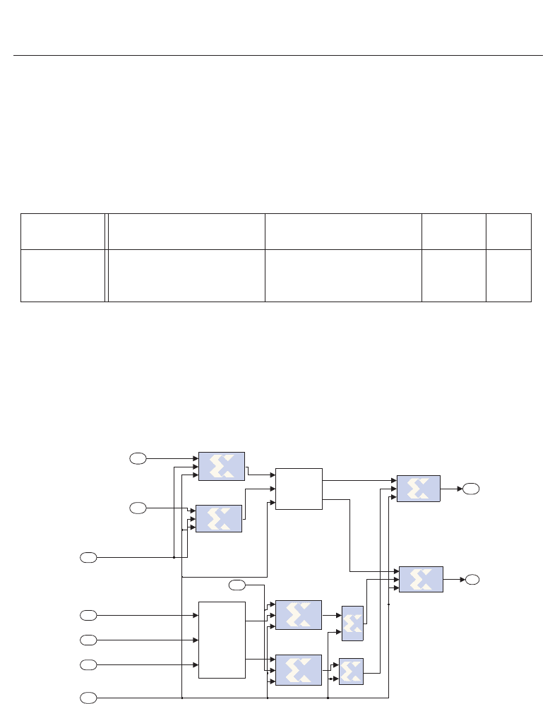
Finally, LOS Doppler has also to be taken into account and must be applied to each Rician
path according to Eq. (2). To achieve this, we use the System Generator’s DDS (Direct Digital
Synthesizer) block that generates a sine and a cosine with the required phase and frequency
parameters. Since the angle of arrival of the LOS component has not been considered in
(Acosta, 2007b), we always set its value to zero, what means that the received Rician paths
arrive straight from the driving direction. This implies that the LOS Doppler is always equal
to the path’s maximum Doppler spread.
!
"#
!
"#
$%%
&
$%%
&
&
'
#
()
$
Fig. 4. Generation and addition of the LOS and NLOS components of each path.
3.4.4 Interpolation and FIR filtering
After adding the LOS and NLOS components according to Eq. (1) (see Fig. 4), the coefficients
must adapt their rate to the rate of the incoming signal (i.e. the signal from our transmitters
276
Advanced Applications of Rapid Prototyping Technology in Modern Engineering
Rapid Prototyping for Evaluating
Vehicular Communications 11
!"
#$
$
#
!"
%!
!
%
Fig. 5. One path’s linear interpolator.
arrives at 10 MHz). These coefficients are generated at a rate that depends on the maximum
Doppler shift and that is much lower than the FPGA’s frequency. Indeed, in a specific
vehicular channel, the implicit sample rate is twice the maximum Doppler shift of all paths. In
the implemented vehicular channel models, this rate fluctuates between 1988 Hz and 3484 Hz
(see Table 3). To avoid designing a complex resampling stage, instead of using the original
coefficient generation rate, we use an effective sample rate that is equal to the nearest superior
integer divider of 10 MHz. Thus, we only need an interpolator (we actually use two cascaded
linear interpolators, whose global interpolation rates are also included in Table 3).
Fig. 5 shows a linear interpolator applied to one of the paths. The way it works is simple:
• At the time instant t , the current coefficient and the one generated at the time instant t
− 1
are copied p times, being p the interpolation factor. Hence, we would have two sets of
upsampled coefficients: s
t
=[
p
s
t
, s
t
, ..., s
t
] and s
t−1
=[
p
s
t−1
, s
t−1
, ..., s
t−1
]. At the time instant
0, the upsampled coefficients at t
− 1 are all equal to 0. If the interpolator is currently in
a time instant superior to 0, it is assumed that there exists a previously interpolated value
y
t−1
.
• Next, the n-th upsampled coefficients from s
t
and s
t−1
are subtracted and divided by p:
Δ
t
=(s
t
n
− s
t−1
n
)/p.
• Finally, Δ
t
is added or subtracted (depending on its sign) to/from the interpolation value
calculated at the time instant t
− 1, obtaining the current output interpolated value: y
t
=
y
t−1
+ Δ
t
.
Finally, the signal from the transmitter is filtered with the interpolated coefficients. Details
about the implemented FIR filter can be found in (Fernández-Caramés, 2010).
3.5 Emulator basic operation
The emulator operation can be summarized as follows:
1. The configuration parameters of the vehicular channel are initially read from registers
(shown in Fig. 2).
2. The emulator starts to generate channel coefficients, both for the LOS and the NLOS
components (illustrated in Figs. 2 to 4).
3. The coefficients are interpolated to have their rate adapted to the incoming signal rate,
passing each path through linear interpolators (like the one shown in Fig. 5). The
interpolation is carried out in two stages, whose interpolation factors depend on the
effective generation rates shown in Table 3. For instance, in the channel RTV-Urban Canyon,
277
Rapid Prototyping for Evaluating Vehicular Communications

12 Will-be-set-by-IN-TECH
the coefficients have an effective generation rate equal to 2500 Hz. Since the incoming
signal rate is 10 MHz, the coefficients need to be interpolated with a global factor of 4,000,
which can be applied in two stages with interpolation factors 2
5
and 5
3
.
4. Finally, the incoming signal is applied to a complex FIR filter that uses the generated
channel coefficients.
4. Upgrading to MIMO
First, note that the channels modeled in (Acosta, 2007b) are based on SISO measurements, but
we use them because they have become the reference for evaluating IEEE 802.11p. Further
investigation is still needed to adapt such channels to multiple-antenna environments, but
when that occurs, the transceivers and channel emulator model presented in this chapter will
continue to be valid, only requiring slight modifications or no modifications at all. Also, for
the sake of brevity, regarding MIMO we will restrict ourselves to IEEE 802.11p transceivers.
4.1 IEEE 802.11p MIMO transceivers
4.1.1 Multiple-antenna transmitter
In the transmitter, the use of several antennas lead us to change our SISO channel estimation
and use orthogonal pilots that constitute matrices called OSTPM (Orthogonal Space-Time
Pilot Matrices). Specifically, we use Hadamard matrices created using Sylvester’s method,
which generates a sequence of matrices that are known as Walsh matrices. Such matrices are
orthogonal in space and time and, in the case of transmitting with two antennas, they are
generated according to:
P
=
p
k
p
k
p
k
−p
k
(3)
where p
k
is the BPSK-modulated pilot symbol transmitted at the k subcarrier. Since IEEE
802.11p uses four pilots inside each OFDM symbol, the pilot matrix is generated by replicating
Equation (3) to obtain a 2
×4 matrix.
Using this scheme, channel estimation only requires simple linear processing. For instance, in
the case of transmitting with two antennas, the received signal at the k-th subcarrier for two
consecutive OFDM symbols would be:
y
1,k
= p
k
h
1,k
+ p
k
h
2,k
+ n
1
y
2,k
= p
k
h
1,k
− p
k
h
2,k
+ n
2
(4)
where n
1
and n
2
are AWGN samples and h
1
and h
2
are the channel coefficients. Thus, the
channel coefficient estimations are obtained as:
ˆ
h
1,k
=
y
1,k
+ y
2,k
2p
k
ˆ
h
2,k
=
y
1,k
− y
2,k
2p
k
(5)
Note that this channel estimation method has several limitations. First, it assumes that the
channel remains constant over two consecutive pilots, so when the Doppler spread is high,
performance will be degraded. The second drawback is related to the pilot generation matrix:
it is only possible to use this pilot scheme when the number of transmit antennas is a power of
two. Moreover, it requires an even number of transmitted OFDM symbols to be transmitted.
In spite of the above mentioned issues, we stick to using this method due to its simplicity and
because the maximum Doppler shift of the implemented channels is 1742 Hz, that corresponds
to a channel coherence time of 574 μs, which is clearly higher than the time required to
transmit two consecutive OFDM symbols (16 μs).
278
Advanced Applications of Rapid Prototyping Technology in Modern Engineering
Rapid Prototyping for Evaluating
Vehicular Communications 13
Apart from the modifications required by the channel estimation step, to exploit space-time
diversity, MIMO systems need an additional coding stage. In the case of 2
×2 system Alamouti
coding is used (Alamouti, 1998), whereas the 4
×4 transceiver implements a quasi-orthogonal
code proposed by Jafarkhani (Jafarkhani, 2000).
4.1.2 Multiple-antenna receiver
At the receiver side the main changes with respect to the SISO system are related to support
diversity schemes. In the SIMO case the system implements the MRC (Maximum-Ratio
Combining) technique, while the MIMO transceiver requires the use of an Alamouti decoder
in the 2
×2 case, and a ML (Maximum-Likelihood) detector otherwise. We do not give herein
more details about the receivers since they use standard MIMO algorithms and techniques.
4.2 MIMO vehicular channel emulation
There are several examples of academic MIMO FPGA-based channel emulators. Some of
them are generic (e.g. (Ren, 2010; Wang, 2008; Zhan, 2009)), while others (e.g. (Eslami, 2009))
are specifically oriented towards the implementation of the IEEE 802.11n reference channel
models. However, none of the existing channel emulators has been explicitly developed for
recreating VTV or RTV environments.
One of the main problems when implementing MIMO channel emulators in an FPGA is that
they require large designs and, therefore, the use of resources has to be optimized. Most of
the channel emulators described in the literature are able to implement the whole system into
only one FPGA. To fit the design into one FPGA, researchers have to save resources using
several clever tricks, being one of the most recurrent the off-line generation of the channel
coefficients (Eslami, 2009; Zhan, 2009). Also, some authors (Eslami, 2009) are able to save up
to 67% of the FPGA resources by applying the channel coefficients in the frequency domain.
These academic developments present at least three drawbacks. First, the use of low-level
description languages such as VHDL slows down the development stage.
The second problem is related to the portability of the channel emulator. A good channel
emulator should be able to work in stand-alone mode, i.e. without needing external devices
to generate and transfer channel coefficients to the FPGA.
The third drawback is related to scalability. As it can be derived from the results exposed in
(Eslami, 2009), when we work with a time-domain based channel emulator, the gate count (i.e.
the number of 2-NAND logic gates that would be required to implement the same number and
type of logic functions) roughly doubles every time we add a transmit and a receive antenna
to the system. Therefore, a scalable solution would have to be able to deal with more inputs
and outputs without requiring such important hardware complexity increases.
The vehicular emulator described in this chapter addresses these three drawbacks: we use
Xilinx System Generator to develop the channel emulator faster than using an HDL, we
optimize our design in order to fit a MIMO twelve-path channel emulator into one FPGA,
we design the emulator bearing in mind that it has to be able to work in stand-alone mode
with minimal modifications and we propose a time-multiplexing solution that has a very low
impact on the emulator design, thus facilitating scalability.
4.3 Refining the emulator: from SISO to MIMO
Our first attempt to expand our SISO emulator to accept more input and output antennas
consisted in creating a SIMO 1
× 2 system by replicating the SISO design. The obtained design
was too large to fit into our FPGA, so we proceeded to optimize it. For the sake of brevity,
we will only cite the three most important optimizations we carried out, whose savings are
279
Rapid Prototyping for Evaluating Vehicular Communications