Hooke R.L. Principles of glacier mechanics
Подождите немного. Документ загружается.

Equipotential surfaces in a glacier 201
Outlet
1
23
∆
z
z
1
z
2
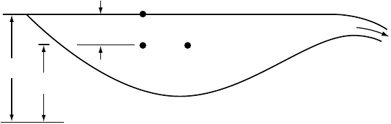
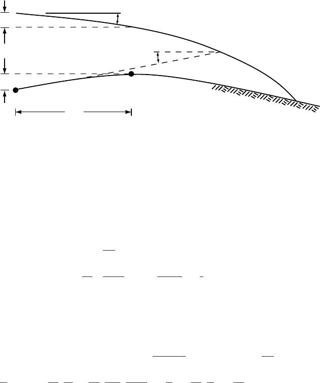
Figure 8.2. Illustration of
difference between pressure
field and potential field.
Over a period of several years Holmlund (1988) carefully mapped
such structures on Storglaci¨aren as ablation exposed ever deeper levels in
the glacier. He also descended into some of the moulins during the winter.
He found that moulins are typically 30–40 m deep, although deeper
ones occur on other glaciers, that channels leading from the bottoms
of moulins are typically meandering and trend in the direction of the
initiating crevasse, and that after some distance the meandering channel
ends in a vertical conduit leading deeper into the glacier.
Shreve (1972) has compared the drainage system we have just
described with one developed in a permeable limestone in which karst
has developed. The anastomosing vein system provides the basic perme-
ability, while the moulins and larger arborescent network of conduits are
the analog of the karst system. Our task now is to consider the geometry
of the system of larger conduits deeper in the glacier, below the level
of Holmlund’s mapping. One possibility is that these conduits are not
vertical, but rather slope steeply downglacier, normal to equipotential
surfaces in the glacier. We develop the theory behind this idea next,
following closely the analysis of Shreve (1972).
Equipotential surfaces in a glacier
In a permeable porous medium, water flows in the direction of the neg-
ative of the maximum gradient of the potential, ,where is defined
by:
=
o
+ P
w
+ ρ
w
gz (8.1)
Here,
o
is a reference potential, P
w
is the pressure in the water, ρ
w
is
the density of water, g is the acceleration of gravity, and z is the elevation
above some datum level such as sea level.
To gain some appreciation for this concept, consider the situation in
a lake (Figure 8.2). Let =
1
at point 1 on the lake surface. Moving
down a distance z to point 2 increases P
w
by ρ
w
gz but decreases the
third term on the right in Equation (8.1)bythe same amount. Therefore
2
=
1
and there is no flow between points 1 and 2. However, if the lake
202 Water flow in and under glaciers
surface slopes gently towards the outlet, moving horizontally at constant
z = z
2
from point 2 to point 3 will result in a decrease in P
w
, and hence
in . Flow will then be toward the position of lower P
w
,which also is
a position of lower .Inother words, it is not the gradient in P
w
that
controls the direction of flow, but the gradient in .
To determine the potential field in a glacier from Equation (8.1), we
must determine P
w
everywhere. P
w
is not hydrostatic because the water
is moving, and most of it is a long way from the surface through many
small passages.
In general, the pressure in the ice, P
i
,isdifferent from that in the
water, and the ice deforms as a result of this pressure difference. P
w
rarely exceeds P
i
significantly, but it can be much less than P
i
.Passages
may thus increase in size slightly at very high water pressures, and they
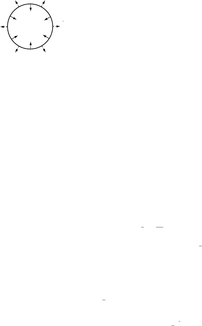
decrease in size rapidly at low pressures. In addition, as noted, heat
generated by viscous dissipation melts conduit walls, enlarging passages
(Figure 8.3). In a steady state, the rate of closure of passages by creep of
ice, u,isequal to the melt rate,
˙
m,sothe net rate of increase in size of the
passages, ˙r =
˙
m − u,is0.(Although mathematically untidy, note that
we have defined positive u as being inward, while positive
˙
m is outward.
This simplifies some of the later equations.)
P
w
u
P
i
m
Figure 8.3. In a steady
state, closure of a cylindrical
conduit, u,isbalanced by
melt, m.
Let us assume that the flow of ice can be represented by ˙ε
e
=(σ
e
/ B)
n
,
that ice is incompressible and isotropic, and that the passages are circular
in cross section. We further define the pressure causing creep closure,
P
c
,by:
P
c
=
P
i
−
P
w
(8.2)
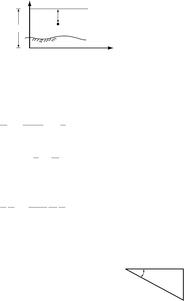
(Figure 8.3). To a good approximation, P
i
= ρ
i
g(H − z), where H is the
elevation of the ice surface above the datum level (Figure 8.4). Then:
u
r
=
P
c
nB
n
(8.3)
(Nye, 1953). This relation will be derived in Chapter 12 (Equation
(12.22)). In the derivation it is assumed that σ
e
= (1/
√
2)σ
rr
,where σ
rr
is
the radial stress deviator. In other words, other components of the devi-
atoric stress tensor, and hence of the strain rate tensor, are assumed to
be negligible (see Equation (2.10)). Thus, there can be no deformation
of the ice other than that resulting from the presence of the passage.
In the present application, in which this assumption is clearly violated,
we add a multiplying factor, K,which is approximately 1. K equals 1
if σ
e
= (1/
√
2)σ
rr
. Rearranging and substituting for P
c
and P
i
,wecan
rewrite Equation (8.2) as:
P
w
= ρ
i
g(H − z) − KnB
u
r
1
n
u ≥ 0 (8.4)
Equipotential surfaces in a glacier 203
H
(H − z)
z
x
Ice surface
Bed
Figure 8.4. Coordinate axes
used in discussion of conduit
closure.
(If u < 0, implying that the passage is opening as a result of water
pressures in excess of the ice pressure, |u|must be used, and the sign of the
second term adjusted accordingly, but u < 0israre in nature.) In excess
of a couple of kilometers from the glacier terminus, parameters in the last
term on the right change relatively little along a tunnel. Thus, combining
Equations (8.1) and (8.4) and taking the derivative with respect to an
arbitrary direction, s, yields:
∂
∂s
= ρ
i
g
∂(H − z)
∂s
+ ρ
w
g
∂z
∂s
(8.5)
To determine the orientations of equipotential planes in the glacier, we
make use of the fact that if s lies in such a plane, ∂/∂s = 0, so:
− (ρ
w
− ρ
i
)
∂z
∂s
= ρ
i
∂ H
∂s
(8.6)
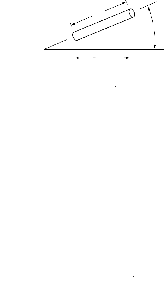
Our objective is to define the dip of this plane, β. The dip in some
horizontal direction, x, will be dz/dx because z is the vertical coordinate
of the plane (Figure 8.5). Therefore, multiply Equation (8.6)by∂s/∂x
and rearrange, thus:
∂z
∂s
∂s
∂x
=−
ρ
i
ρ
w
− ρ
i
∂ H
∂s
∂s
∂x
or, inserting numerical values for the respective densities, letting α =
dH/dx, the slope of the glacier surface, and noting that tan β = dz/dx:
β ≈−tan
−1
(11α) (8.7)
Thus, the equipotential planes dip upglacier (note the minus sign) with
dx
dz
ds
b
Figure 8.5. Sloping
conduit showing how ds
and β are defined.
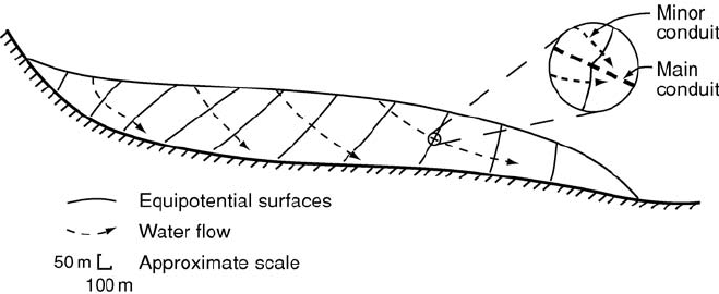
a slope of about 11 times the slope of the glacier surface (Figure 8.6), a
result first obtained by Shreve (1972), and water entering the glacier
through a moulin should reach the bed of the glacier some dis-
tance downglacier from the entry point. In support of this, Iken and
Bindschadler (1986) found that pressure fluctuations in boreholes drilled
to the bed of Findelengletscher, just below the firn edge, did not correlate
with marked variations in stream flow entering nearby moulins. Rather,
the pressure fluctuations seemed to reflect a slower delayed input of water
through the snow cover above the firn edge.
204 Water flow in and under glaciers
Figure 8.6. Longitudinal section of a glacier showing upglacier-dipping
equipotential surfaces and the theoretical directions of englacial water flow. Inset
shows dimpling of an equipotential surface and consequent diversion of flow in
smaller passages toward the main conduit. (After Hooke, 1989, Figure 1.)
Rigorously, the equipotential surfaces are defined only within the
water passages, but with suitable caution, they can be treated as though
they were defined throughout the glacier. Because P
w
< P
i
under normal
conditions, is slightly lower in the conduit than in the surrounding
ice. Thus, the equipotential surfaces are dimpled in the vicinity of the
conduits. As decreases downglacier, the dimples point upglacier as
shown in Figure 8.6.With the use of the theory presented below, it can be
shown that the difference between P
i
and P
w
increases with increasing
conduit size, so dimples around larger conduits are larger. Thus, water
in smaller conduits flowing normal to equipotential surfaces will be
deflected toward the larger ones. This strengthens the tendency of the
conduit system to evolve toward an arborescent pattern.
Alternative derivation of equipotential-plane dip
Consider the situation in Figure 8.7. There is a conduit along the bed
between points 1 and 2. We wish to determine under what conditions
the upglacier slope of the hill will be parallel to an equipotential plane
so that water in the conduit will not flow. The ice pressure at (1) is
P
i1
= ρ
i
g(h
1
+ h
2
+ h), and that at (2) is P
i2
= ρ
i
gh
2
.Inthe absence
of water flow and conduit closure, the pressure in the water at (1), P
w
,
would be the sum of P
i2
plus the hydrostatic head in the conduit, ρ
w
gh
1
.
If P
i1
> P
w
, the conduit will begin to close and water will be forced out
over the hill. Thus, the condition we seek is P
i1
= P
w
, or:
ρ
i
g(h
1
+ h
2
+ h) = ρ
i
gh
2
+ ρ
w
gh
1
(8.8)
Solving this for h
1
,dividing by x, noting that α =−h/x and tan
β =h
1
/x, and inserting numerical values for the densities leads directly
to Equation (8.7)Q.E.D.
Melt rates in conduits 205
(1)
(2)
∆ x
b
a
∆ h
h
2
h
1
Figure 8.7. Sketch illustrating alternative derivation of dip of equipotential
planes in a glacier.
Melt rates in conduits
Let us now consider the rate of melting of conduit walls, following Shreve
(1972). The total amount of energy available per unit length of conduit,
s, per unit time is:
Q
∂
∂s
s
m
3
s
N/m
2
m
m =
N −m
s
=
J
s
(8.9)
Some of this energy must be used to warm the water to keep it at the
pressure melting point as ice thins in the downglacier direction. The rest
is available to melt ice, thus:
˙
m s (2r ρ
i
L) + ρ
w
C
w
C
∂(H − z)
∂s
ρ
i
g sQ= Q
∂
∂s
s
m
s
mm
kg
m
3
J
kg
kg
m
3
J
kgK
K
N/m
2
m
m
kg
m
3
m
s
2
m
m
3
s
(8.10)
Here, r is the radius of the conduit, L is the latent heat of fusion, C
w
is the
heat capacity of water, and C is the change in the melting point per unit
of pressure (see Equation (2.2)). As you will see from inspection of the
terms and the dimensions of the various quantities in them, the first term
on the left is the energy used to melt tunnel walls, and the second is the
energy needed to warm the water to keep it at the pressure melting point.
Here, we have implicitly taken the positive s-direction to be upglacier,
in the direction opposite to that of the water flow. Thus, both ∂/∂s and
∂(H −z)/∂s are positive.
It is common to define k = ρ
w
C
w
C. Inserting numerical values
(ρ
w
= 1000 kg m
−3
, C
w
= 4180 J kg
−1
K
−1
, and C = 0.074 × 10
−6
KPa
−1
)wefind that k =0.309 and that it is dimensionless. If we assume
that the water is saturated with air, and adjust C accordingly, k = 0.410.
206 Water flow in and under glaciers
Then, using Equation (8.5) and dividing by s yields:
˙
m(2rρ
i
L) +k
∂
∂s
− ρ
w
g
∂z
∂s
Q = Q
∂
∂s
(8.11)
or solving for
˙
m:
˙
m =
Q
(1 −k)
∂
∂s
+ kρ
w
g
∂z
∂s
2rρ
i
L
(8.12)
It is interesting to insert some numbers into this equation to get a
sense of the magnitude of
˙
m. Consider a horizontal tunnel so ∂z/∂s =0.
Suppose the tunnel has a diameter of 0.5 m and that it is under a glacier
with a surface slope of 0.01. We now need a relation between Q and the
tunnel roughness. The Gaukler–Manning–Strickler equation is one of
two that are commonly used for such calculations. It is:
v =
Q
r
2
=
R
2/3
S
1/2
n
(8.13)
Here, v is the mean velocity over the tunnel cross section, R is the
hydraulic radius of the tunnel, or the cross-sectional area divided by
the perimeter (so R = r/2incircular tunnels), S is the nondimensional
headloss:
S =
1
ρ
w
g
∂
∂s
(8.14)
which is approximately equal to the glacier surface slope, and n
is known
as the Manning roughness coefficient. For smooth channels, n
may be as
low as 0.005 m
−1/3
s, but studies of floods, called j¨okulhlaups, resulting
from drainage of ice-dammed lakes through subglacial conduits yield
values ranging from 0.08 to 0.12 m
−1/3
s (Bj¨ornsson, 1992). A still higher
value was obtained from dye-trace experiments on Storglaci¨aren; flow
velocities there suggested n
≈ 0.2 m
−1/3
s (Seaberg et al., 1988; Hock
and Hooke, 1993). Where roughness elements on the tunnel walls and
floor are large in comparison with the tunnel size, n
will be higher; this
is probably responsible for the relatively high value from Storglaci¨aren.
Choosing an intermediate value of 0.1 m
−1/3
s, Equation (8.13)gives a
mean velocity of about 0.25 m s
−1
,orQ ≈ 0.05 m
3
s
−1
, and Equation
(8.14)gives∂/∂s ≈ 98 N m
−3
. Whence
˙
m ≈ 0.22 m a
−1
. This may not
seem like a lot but, volumetrically, the amount of ice melted in a year is
2.6 times the size of the original conduit.
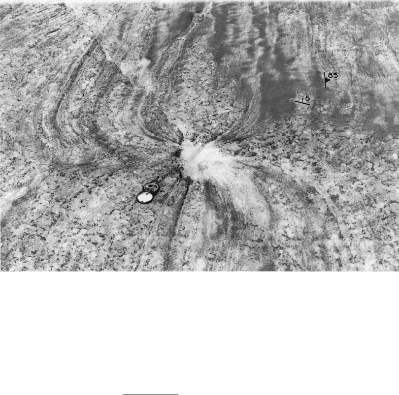
A consequence of this melting and the resulting inward flow of ice
towards the conduit is that structures such as foliation in the ice are also
bent inward. A beautiful example of this is shown in Figure 8.8.
Melt rates in conduits 207
Figure 8.8. Foliation deflected into a conduit by inward flow of ice in response
to melting of conduit walls. (From Taylor, 1963, Figure 11. Reproduced with
permission of the author and the International Glaciological Society.)
Some heat may also be advected into the glacier in water originating
at the glacier surface and entering the englacial conduit system by way
of moulins. The melt rate from such water,
˙
m
s
, is:
˙
m
s
=
Qρ
w
C
w
(∂/∂s)
2rρ
i
L
(8.15)
(Shreve, 1972). Here, ∂/∂s is the rate at which the water cools as it flows
through the conduit. If we assume that ∂
/∂s ≈ 0.1Kkm
−1
and use the
discharge in the previous example,
˙
m
s
≈ 0.08 m a
−1
. Thus, this is a heat
source that cannot be neglected. A possible mitigating factor, however,
is that ice crystals are often carried in streams on a glacier surface. Thus,
some of the heat would be used to melt these crystals rather than the
conduit walls. It is not clear how the energy will be partitioned in this
situation. One would also expect most of this heat to be consumed in the
moulin itself or in the first few hundred meters of flow in an englacial
passage.
208 Water flow in and under glaciers
Water pressures in subglacial conduits
on hard beds
Our next task is to determine the water pressure in conduits. Our dis-
cussion focuses on subglacial conduits on hard beds, but much of the
development is equally applicable to englacial ones that are deep enough
that P
w
is greater than atmospheric pressure. The water pressure in sub-
glacial conduits is of considerable interest owing to its effect on the
sliding speed.
Qualitatively, we expect P
w
to increase upglacier because the ice
thickness increases, and P
c
must remain relatively constant so that
u =
˙
m. The increase in P
w
,ormore rigorously in , provides the poten-
tial gradient that drives water toward the terminus. Less obvious is the
wayinwhich P
w
should vary with Q,yet this is quite important because
if P
w
decreases as Q increases, water will be drawn from smaller con-
duits toward larger ones, leading to the development of an arborescent
drainage network. Conversely, if P
w
increases as Q increases, the conduit
system will tend to remain braided or distributed.Inthe type of system
that we have been discussing, consisting of conduits that may vary in
size but not in shape in the longitudinal direction, it turns out that P
w
decreases as Q increases. However, in subglacial drainage systems in
which conduits locally lie in the lee of bedrock steps, so that conduit
geometry is controlled by the steps, the reverse may be true. Qualita-
tive explanations of these phenomena are difficult because the result
depends upon the details of the way in which conduit size changes with
discharge and in which u and
˙
m change with conduit size. We thus turn
to a quantitative analysis, following closely the work of R¨othlisberger
(1972). Initially, we will focus on circular conduits.
We start with the steady-state condition, u =
˙
m, and obtain an expres-
sion representing this condition by combining Equations (8.3) and (8.12),
thus:
r
P
c
nB
n
=
Q
(1 −k)
∂
∂s
+ kρ
w
g
∂z
∂s
2rρ
i
L
(8.16)
Noting that R = r/2incircular conduits and solving Equations (8.13)
and (8.14) for r yields:
r
2
=
2
1
2
n
3
4
Q
3
4
(ρ
w
g)
3
8
3
4
∂
∂s
3
8
(8.17)
Combining Equations (8.16) and (8.17)toeliminate r, letting:
D = 2
3
2
1
4
(ρ
w
g)
3
8
ρ
i
L = 3.63×10
10
N
m
2
11
8
m
−
3
8
Water pressures in subglacial conduits 209
d x
d
s
b
Figure 8.9. Definition of ds
in terms of β and dx.
and simplifying, we obtain:
∂
∂s
11
8
+
k
1 −k
ρ
w
g
∂z
∂s
∂
∂s
3
8
=
Dn
3
4
P
n
c
(1 −k)Q
1/4
(nB)
n
(8.18)
We now need to relate ∂/∂s to P
w
and to the geometry of the tunnel
system. Differentiating Equation (8.1) with respect to s yields:
∂
∂s
=
∂ P
w
∂s
+ ρ
w
g
∂z
∂s
(8.19)
Referring to Figure 8.9,wesee that:
ds =
dx
cos β
(8.20)
so, noting again that dz/dx = tan β, Equation (8.19) becomes:
∂
∂s
=
dP
w
dx
+ ρ
w
g tan β
cos β (8.21)
Letting:
G =
dP
w
dx
+ ρ
w
g tan β
(8.22)
and using Equations (8.21) and (8.22)inEquation (8.18) yields:
G
11
8
− kG
11
8
+ k
G −
dP
w
dx
G
3
8
=
Dn
3
4
P
n
c
Q
1/4
(nB)
n
cos
11/8
β
(8.23)
Canceling the two terms in kG
11/8
and replacing P
c
and G by their
equivalents from Equations (8.2) and (8.22) results in the relation we
have been seeking:
dP
w
dx
+ ρ
w
g tan β
11
8
− k
dP
w
dx
+ ρ
w
g tan β
3
8
dP
w
dx
=
Dn
3
4
(P
i
− P
w
)
n
Q
1/4
(nB)
n
cos
11/8
β
(8.24)
Equation (8.24)isanonlinear differential equation that can be inte-
grated numerically to obtain the water pressure, P
w
,inaconduit as a
function of distance from the terminus, x = 0, subject to the boundary
condition that P
w
= 0atthe terminus. If the conduit is not full of water
210 Water flow in and under glaciers
at the terminus, the boundary condition applies some distance upglacier
from the terminus, where the conduit first becomes full, and the integra-
tion must start at this point. (Atmospheric pressure is ignored, as it is
uniform over the area.) To carry out the integration, one uses the surface
and bed topography along the course of the conduit to calculate P
i
and
β at each step, dx.
In the derivation of Equation (8.24), we assumed that the conduit
was circular. If, instead, we were to assume that it was semicircular,
a more rational assumption for a conduit on a hard bed, and modified
Equations (8.12) and (8.13) accordingly, we would find that the form
of Equation (8.24)was unchanged. However, D would be 2.00 × 10
10
(N m
−2
)
11/8
m
−3/8
.Wewould then be assuming, implicitly, that Equation
(8.3) still applied. These assumptions will be discussed further in the next
section.
Equation (8.24)isclearly quite complicated, but we can gain insight
into the general behavior of the water pressure field by studying some
idealized cases. Consider, for example, a circular tunnel at the base of a
slab of ice, 250 m thick, resting on a horizontal bed. Then, β = 0 and
P
i
=constant. R¨othlisberger presented some solutions for this case. They
are shown in Figure 8.10,inwhich the water pressure is represented on the
ordinate by the height to which water would rise in a vertical borehole
that intersects the tunnel, or the piezometric head.Aline connecting
these water levels in a series of boreholes along a tunnel is called the
hydraulic grade line or energy grade line, and its slope is ∂/∂s. The
water equivalent line in Figure 8.10 is the piezometric head at which
the glacier would float. The values of n
and B used in the calculations
are shown.
Aside from the obvious increase in P
w
in the upglacier direction, thus
providing the hydraulic head necessary to drive the flow on a horizontal
bed, there are two characteristics of the patterns in Figure 8.10 that merit
comment.
1. Water pressures increase as B decreases (compare curves (1), (2) and
(3)). This is because lower values of B imply softer ice and hence
higher tunnel closure rates. Thus, higher pressures are necessary to
reduce the closure rate so that u =
˙
m.
2. Water pressures increase as Q decreases (curves (3), (3a), and (3b)).
Although obvious from inspection of Equation (8.24), this is some-
what counterintuitive. Consider the consequences of halving Q, hold-
ing, for the moment, P
w
and hence ∂/∂s constant.
˙
m will thus be
halved (Equation (8.12)). Clearly, halving Q will require a decrease
in the cross-sectional area of the conduit, A.NowA varies as r
2
but