Hibbeler R.C. Structural Analysis
Подождите немного. Документ загружается.


250 CHAPTER 6INFLUENCE LINES FOR S TATICALLY DETERMINATE STRUCTURES
6
6.7 Absolute Maximum Shear and Moment
In Sec. 6–6 we developed the methods for computing the maximum shear
and moment at a specified point in a beam due to a series of concentrated
moving loads. A more general problem involves the determination of
both the location of the point in the beam and the position of the loading
on the beam so that one can obtain the absolute maximum shear and
moment caused by the loads. If the beam is cantilevered or simply
supported, this problem can be readily solved.
Shear. For a cantilevered beam the absolute maximum shear will
occur at a point located just next to the fixed support. The maximum
shear is found by the method of sections, with the loads positioned
anywhere on the span, Fig. 6–33.
For simply supported beams the absolute maximum shear will occur just
next to one of the supports. For example, if the loads are equivalent, they
are positioned so that the first one in sequence is placed close to the
support, as in Fig. 6–34.
Moment. The absolute maximum moment for a cantilevered beam
occurs at the same point where absolute maximum shear occurs, although
in this case the concentrated loads should be positioned at the far end of
the beam, as in Fig. 6–35.
For a simply supported beam the critical position of the loads and the
associated absolute maximum moment cannot, in general, be determined
by inspection. We can, however, determine the position analytically. For
purposes of discussion, consider a beam subjected to the forces
shown in Fig. 6–36a. Since the moment diagram for a series of concen-
trated forces consists of straight line segments having peaks at each
force, the absolute maximum moment will occur under one of the forces.
Assume this maximum moment occurs under The position of the
loads on the beam will be specified by the distance x, measured
from to the beam’s centerline as shown. To determine a specific value
of x, we first obtain the resultant force of the system, and its distanceF
R
,
F
2
F
3
F
2
,F
1
,
F
2
.
F
3
F
2
,F
1
,
Fig. 6–33
V
abs
max
V
abs
max
M
abs
max
F
1
F
2
F
3
F
R
B
y
A
y
AB
x
d
2
d
1
L
—
2
L
—
2
(a)
( x)
_
x¿
_
x¿
F
1
d
1
A
y
L
—
2
( x)
M
2
V
2
(b)
Fig. 6–34
Fig. 6–35
Fig. 6–36

6.7 ABSOLUTE MAXIMUM SHEAR AND MOMENT 251
6
measured from Once this is done, moments are summed about B,
which yields the beam’s left reaction, that is,
If the beam is sectioned just to the left of the resulting free-body
diagram is shown in Fig. 6–36b. The moment under is therefore
For maximum we require
or
Hence, we may conclude that the absolute maximum moment in a
simply supported beam occurs under one of the concentrated forces, such
that this force is positioned on the beam so that it and the resultant force
of the system are equidistant from the beam’s centerline. Since there are a
series of loads on the span (for example, in Fig. 6–36a), this
principle will have to be applied to each load in the series and the
corresponding maximum moment computed. By comparison, the largest
moment is the absolute maximum.As a general rule, though, the absolute
maximum moment often occurs under the largest force lying nearest the
resultant force of the system.
Envelope of Maximum Influence-Line Values. Rules or
formulations for determining the absolute maximum shear or moment
are difficult to establish for beams supported in ways other than the
cantilever or simple support discussed here. An elementary way to
proceed to solve this problem, however, requires constructing influence
lines for the shear or moment at selected points along the entire length
of the beam and then computing the maximum shear or moment in the
beam for each point using the methods of Sec. 6–6. These values when
plotted yield an “envelope of maximums,” from which both the absolute
maximum value of shear or moment and its location can be found.
Obviously, a computer solution for this problem is desirable for
complicated situations, since the work can be rather tedious if carried out
by hand calculations.
F
3
F
2
,F
1
,
x =
x
¿
2
dM
2
dx
=
-2F
R
x
L
+
F
R
x¿
L
= 0
M
2
=
F
R
L
4
-
F
R
x¿
2
-
F
R
x
2
L
+
F
R
xx¿
L
- F
1
d
1
=
1
L
1F
R
2c
L
2
- 1x¿-x2da
L
2
- xb- F
1
d
1
M
2
= A
y
a
L
2
- xb- F
1
d
1
©M = 0;
F
2
M
2
F
2
,
A
y
=
1
L
1F
R
2c
L
2
- 1x¿-x2d©M
B
= 0;
A
y
,
F
2
.x¿
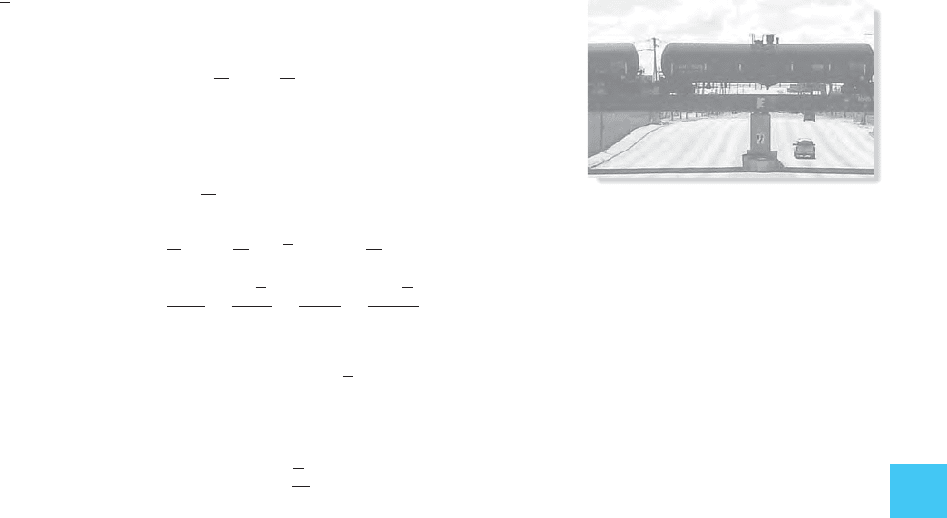
The absolute maximum moment in this
girder bridge is the result of the moving
concentrated loads caused by the wheels of
these train cars. The cars must be in the
critical position, and the location of the point
in the girder where the absolute maximum
moment occurs must be identified.

252 CHAPTER 6INFLUENCE LINES FOR S TATICALLY DETERMINATE STRUCTURES
6
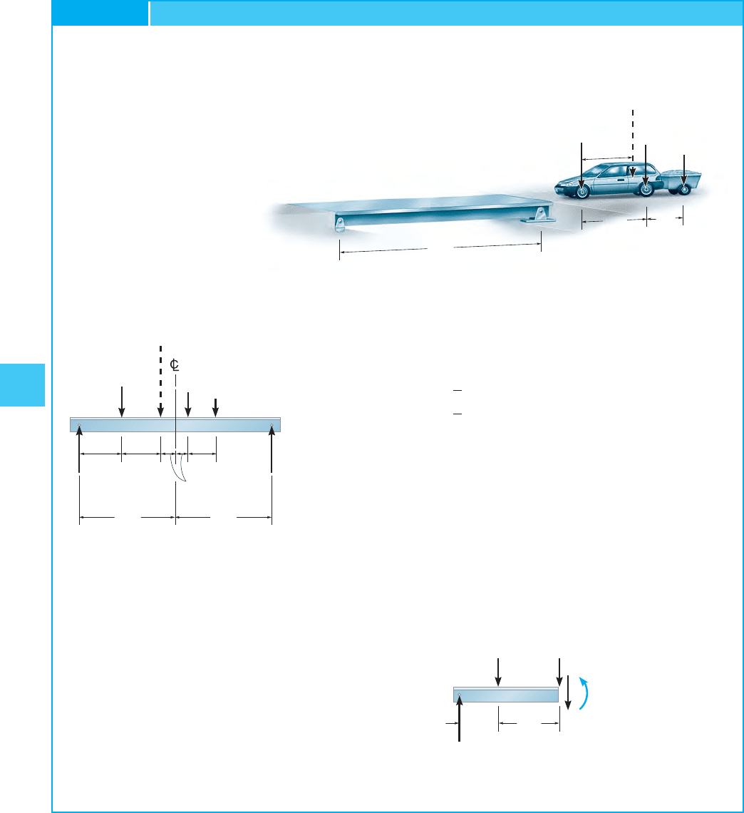
Determine the absolute maximum moment in the simply supported
bridge deck shown in Fig. 6–37a.
EXAMPLE 6.21
SOLUTION
The magnitude and position of the resultant force of the system are
determined first, Fig. 6–37a. We have
Let us first assume the absolute maximum moment occurs under
the 1.5-k load. The load and the resultant force are positioned
equidistant from the beam’s centerline, Fig. 6–37b. Calculating
first, Fig. 6–37b, we have
Now using the left section of the beam, Fig. 6–37c, yields
M
S
= 21.7 k
#
ft
-2.50116.672+ 21102+ M
S
= 0d +©M
S
= 0;
-A
y
1302+ 4.5116.672= 0
A
y
= 2.50 kd +©M
B
= 0;
A
y
x = 6.67 ft
4.5x
= 1.51102+ 11152e +M
R
C
=©M
C
;
F
R
= 2 + 1.5 + 1 = 4.5 k+TF
R
=©F;
A
y
2.5 k
10 ft
M
S
V
S
1.5 k2 k
6.67 ft
(c)
F
R
4.5 k
A
B
15 ft
A
y
B
y
(
b
)
15 ft
2 k
1.5 k
1 k
6.67 ft 6.67 ft
1.67 ft
5 ft
10 ft
1 k
2 k
F
R
4.5 k
_
x6.67 ft
30 ft
A
B
C
(a)
5 ft
1.5 k
Fig. 6–37

6.7 ABSOLUTE MAXIMUM SHEAR AND MOMENT 253
6
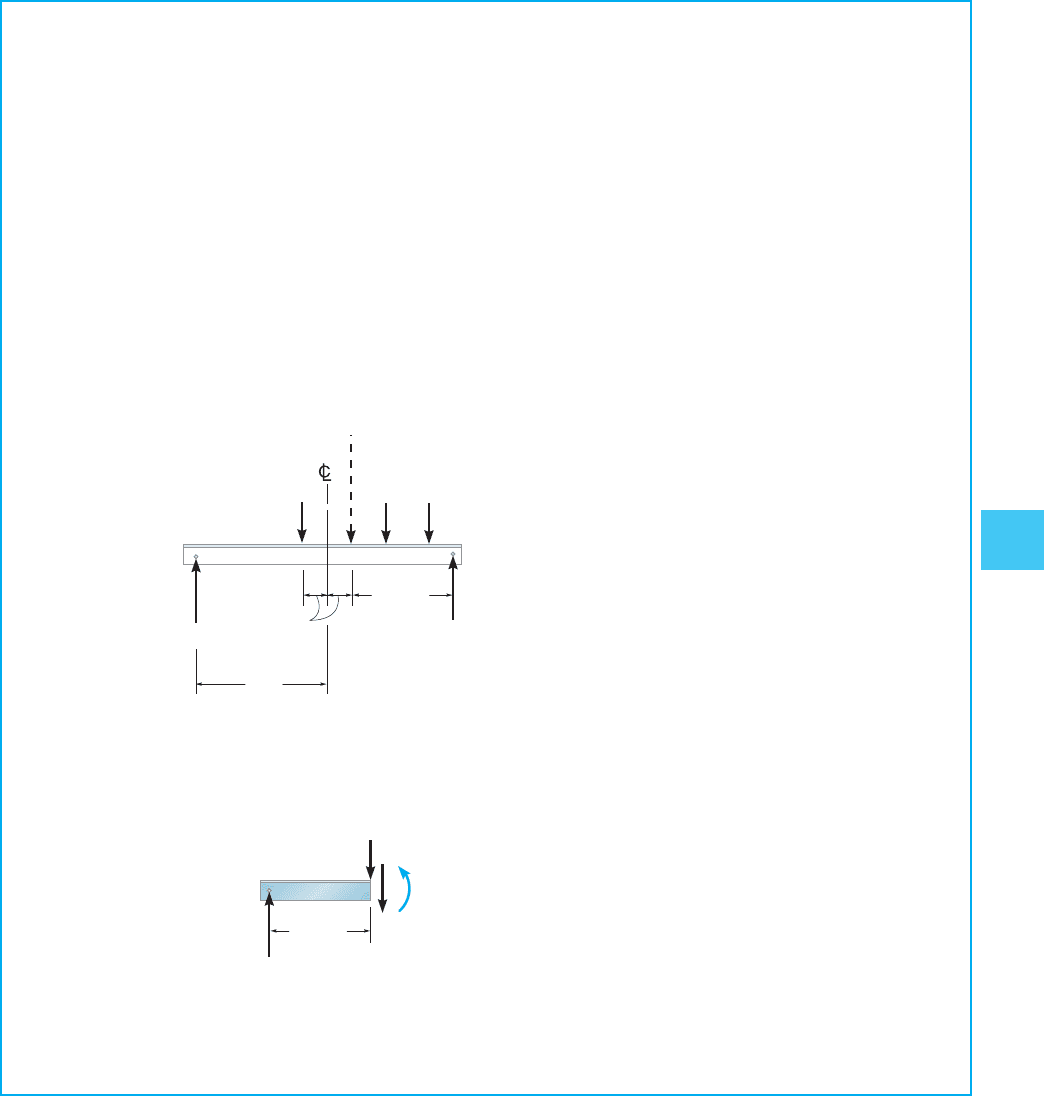
There is a possibility that the absolute maximum moment may
occur under the 2-k load, since and is between both 2 k
and 1.5 k. To investigate this case, the 2-k load and are positioned
equidistant from the beam’s centerline, Fig. 6–37d. Show that
as indicated in Fig. 6–37e and that
By comparison, the absolute maximum moment is
Ans.
which occurs under the 1.5-k load, when the loads are positioned on
the beam as shown in Fig. 6–37b.
M
S
= 21.7 k
#
ft
M
S
= 20.4 k
#
ft
A
y
= 1.75 k
F
R
F
R
2 k 7 1.5 k
A
y
1.75 k
11.67 ft
M
S
V
S
2 k
(e)
F
R
4.5 k
15 ft
A
y
B
y
(
d
)
2 k 1.5 k
3.33 ft
11.67 ft
1 k

254 CHAPTER 6INFLUENCE LINES FOR S TATICALLY DETERMINATE STRUCTURES
6
The truck has a mass of 2 Mg and a center of gravity at G as shown in
Fig. 6–38a. Determine the absolute maximum moment developed in
the simply supported bridge deck due to the truck’s weight.The bridge
has a length of 10 m.
SOLUTION
As noted in Fig. 6–38a, the weight of the truck,
and the wheel reactions have been calculated by statics.
Since the largest reaction occurs at the front wheel, we will select this
wheel along with the resultant force and position them equidistant from
the centerline of the bridge, Fig. 6–38b. Using the resultant force rather
than the wheel loads, the vertical reaction at B is then
The maximum moment occurs under the front wheel loading. Using
the right section of the bridge deck, Fig. 6–38c, we have
Ans.M
s
= 39.7 kN
#
m
8.82914.52- M
s
= 0d +©M
s
= 0;
B
y
= 8.829 kN
B
y
1102- 19.6214.52= 0d +©M
A
= 0;
19.62 kN,
2110
3
2kg19.81 m/s
2
2=
EXAMPLE 6.22
(a)
6.54 kN 13.08 kN
1 m2 m
19.62 kN
G
5 m 5 m
(b)
A
B
A
y
B
y
6.54 kN
13.08 kN
13.08 kN
8.83 kN
0.5 m
0.5 m
19.62 kN
4.5 m
V
s
M
s
Fig. 6–38
(c)

6.7 ABSOLUTE MAXIMUM SHEAR AND MOMENT 255
6
6–59. Determine the maximum moment at point C on the
single girder caused by the moving dolly that has a mass of
2 Mg and a mass center at G. Assume A is a roller.
6–62. Determine the maximum positive moment at the
splice C on the side girder caused by the moving load which
travels along the center of the bridge.
PROBLEMS
*6–60. Determine the maximum moment in the
suspended rail at point B if the rail supports the load of
2.5 k on the trolley.
6–63. Determine the maximum moment at C caused by
the moving load.
*6–64. Draw the influence line for the force in member IH
of the bridge truss. Determine the maximum force (tension
or compression) that can be developed in this member
due to a 72-k truck having the wheel loads shown. Assume
the truck can travel in either direction along the center of the
deck, so that half its load is transferred to each of the two
side trusses. Also assume the members are pin connected at
the gusset plates.
G
5 m 5 m 5 m
C
B
A
1.5 m
0.5 m
Prob. 6–59
8 ft 8 ft6 ft6 ft
ABC
2.5 k
2 ft
1 ft
Prob. 6–61
8 ft 8 ft6 ft6 ft
ABC
2.5 k
2 ft
1 ft
Prob. 6–60
BCA
8 m 8 m
8 m
4 kN
4 m
8 kN
Prob. 6–62
15 ft 15 ft
A
C
B
2 ft
1 ft
2400 lb
Prob. 6–63
JIHG
A
BCDE
K
L
M
10 ft
10 ft
F
32 k
32 k
8 k
20 ft 20 ft 20 ft 20 ft 20 ft
25 ft
15 ft
Prob. 6–64
6–61. Determine the maximum positive shear at point B
if the rail supports the load of 2.5 k on the trolley.

256 CHAPTER 6INFLUENCE LINES FOR S TATICALLY DETERMINATE STRUCTURES
6
6–65. Determine the maximum positive moment at
point C on the single girder caused by the moving load.
*6–68. Draw the influence line for the force in member IC
of the bridge truss. Determine the maximum force (tension
or compression) that can be developed in the member
due to a 5-k truck having the wheel loads shown. Assume
the truck can travel in either direction along the center of
the deck, so that half the load shown is transferred to each
of the two side trusses. Also assume the members are pin
connected at the gusset plates.
6–66. The cart has a weight of 2500 lb and a center of
gravity at G. Determine the maximum positive moment
created in the side girder at C as it crosses the bridge.
Assume the car can travel in either direction along the
center of the deck, so that half its load is transferred to each
of the two side girders.
6–69. The truck has a mass of 4 Mg and mass center at
and the trailer has a mass of 1 Mg and mass center at
Determine the absolute maximum live moment developed
in the bridge.
G
2
.
G
1
,
6–67. Draw the influence line for the force in member BC
of the bridge truss. Determine the maximum force (tension
or compression) that can be developed in the member
due to a 5-k truck having the wheel loads shown. Assume
the truck can travel in either direction along the center of the
deck, so that half the load shown is transferred to each of
the two side trusses. Also assume the members are pin
connected at the gusset plates.
6–70. Determine the absolute maximum live moment in
the bridge in Problem 6–69 if the trailer is removed.
5 m
AB
2 m
1.5 m
4 kN
6 kN
8 kN
5 m
C
Prob. 6–65
8 ft 8 ft
AB
1.5 ft 1 ft
G
C
Prob. 6–66
JI H G
DCB
E
F
15 ft
2 k
3 k
8 ft
A
20 ft 20 ft 20 ft 20 ft
Probs. 6–67/6–68
8 m
AB
G
1
G
2
1.5 m
0.75 m
1.5 m
Prob. 6–69
8 m
AB
G
1
G
2
1.5 m
0.75 m
1.5 m
Prob. 6–70

6.7 ABSOLUTE MAXIMUM SHEAR AND MOMENT 257
6
6–71. Determine the absolute maximum live shear
and absolute maximum moment in the jib beam AB
due to the 10-kN loading. The end constraints require
0.1 m … x … 3.9 m.
6–73. Determine the absolute maximum moment in the
girder bridge due to the truck loading shown. The load is
applied directly to the girder.
*6–72. Determine the maximum moment at C caused by
the moving loads.
6–74. Determine the absolute maximum shear in the beam
due to the loading shown.
4 m
x
AB
10 kN
Prob. 6–71
20 ft 30 ft
C
AB
2 k2 k
4 k
6 k
3 ft 4 ft 3 ft
Prob. 6–72
B
80 ft
20 ft
8 ft
10 k
15 k
7 k
3 k
4 ft
A
Prob. 6–73
12 m
20 kN
25 kN
40 kN
4 m
AB
1.5 m
Prob. 6–75
12 m
20 kN
25 kN
40 kN
4 m
AB
1.5 m
Prob. 6–74
6–75. Determine the absolute maximum moment in the
beam due to the loading shown.

258 CHAPTER 6INFLUENCE LINES FOR S TATICALLY DETERMINATE STRUCTURES
6
*6–76. Determine the absolute maximum shear in the
bridge girder due to the loading shown.
6–79. Determine the absolute maximum shear in the beam
due to the loading shown.
6–78. Determine the absolute maximum moment in the
girder due to the loading shown.
6–81. The trolley rolls at C and D along the bottom and
top flange of beam AB. Determine the absolute maximum
moment developed in the beam if the load supported by the
trolley is 2 k. Assume the support at A is a pin and at B a
roller.
30 ft
8 ft
B
A
10 k
6 k
Prob. 6–77
30 ft
8 ft
B
A
10 k
6 k
Prob. 6–76
25 ft
10 k
8 k
3 k
2 ft2 ft3 ft
4 k
Prob. 6–78
30 ft
3 k
6 k
2 k
3 ft3 ft5 ft
4 k
Prob. 6–80
30 ft
3 k
6 k
2 k
3 ft3 ft5 ft
4 k
Prob. 6–79
A
D
B
C
1 ft
0.5 ft
20 ft
Prob. 6–81
6–77. Determine the absolute maximum moment in the
bridge girder due to the loading shown.
*6–80. Determine the absolute maximum moment in the
bridge due to the loading shown.

PROJECT PROBLEMS 259
6
6–1P. The chain hoist on the wall crane can be placed
anywhere along the boom and has a
rated capacity of 28 kN. Use an impact factor of 0.3 and
determine the absolute maximum bending moment in the
boom and the maximum force developed in the tie rod BC.
The boom is pinned to the wall column at its left end A.
Neglect the size of the trolley at D.
(0.1 m 6 x 6 3.4 m)
6–2P. A simply supported pedestrian bridge is to be
constructed in a city park and two designs have been
proposed as shown in case a and case b. The truss members
are to be made from timber.The deck consists of 1.5-m-long
planks that have a mass of .A local code states the
live load on the deck is required to be 5 kPa with an impact
factor of 0.2. Consider the deck to be simply supported on
stringers. Floor beams then transmit the load to the bottom
joints of the truss. (See Fig. 6–23.) In each case find the
member subjected to the largest tension and largest
compression load and suggest why you would choose one
design over the other. Neglect the weights of the truss
members.
20 kg>m
2
PROJECT PROBLEMS
0.75 m
3 m
x
0.5 m
0.1 m
28 kN
A
D
B
C
Prob. 6–1P
E
1.25 m 1.25 m 1.25 m 1.25 m
1.25 m
case b
A
BCD
FGH
1.25 m 1.25 m 1.25 m 1.25 m
1.25 m
case a
A
BCD
E
E
FGH
Prob. 6–2P
