Heitjans P., Karger J. (Eds.). Diffusion in Condensed Matter: Methods, Materials, Models
Подождите немного. Документ загружается.

21 Concept of Mismatch and Relaxation 863
example has been given in Fig. 21.2. Wherever detected, high-frequency
plateau conductivities are found to obey the Arrhenius law with an
activation energy lower than E
dc
[3,7, 10–12].
(iv) Typically, the shape of σ(ν), as observed in a log-log plot below the
microwave regime, does not depend on temperature. Therefore, a master
curve is obtained when these sections of the conductivity spectra are
shifted and superimposed. This is the time-temperature superposition
principle [13–17].
(v) In a log-log plot of σ · T versus frequency, the onset of the dispersion is
often found to occur along a straight line with a slope of one, implying
that the onset frequency and σ
dc
· T are both activated with E
dc
.This
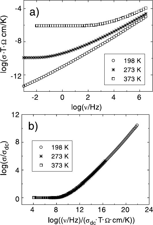
is the so-called Summerfield scaling [18], exemplified in Fig. 21.6 where
conductivity spectra of glassy 0.3Na
2
O · 0.7B
2
O
3
taken at different
temperatures have been scaled to fall on a single master curve.
(vi) Master curves constructed from spectra σ(ν)ofalargenumberofdif-
ferent ionic materials with disordered structures are surprisingly similar
in shape [15, 17, 19].
(vii) At any temperature, the initial part of σ(ν) roughly follows the Jonscher
power law, i.e., σ(ν) − σ(0) ∝ ν
p
with an exponent p between 0.6 and
0.7 in most cases. This behaviour, found in a broad variety of materials,
is often called universal dynamic response (UDR) [20].
(viii) Two-dimensional ion conductors such as the beta aluminas [21], crystals
and glasses with low number densities of mobile ions, see Sect. 21.9
and [17], and mixed cation glasses [22,23] exhibit a particularly gradual
onset of the dispersion of σ(ν).
(ix) As temperature is decreased, the slope of σ(ν) in the log-log plot
approaches the value of one at any given audio or radio frequency,
while the conductivity becomes decreasingly temperature-dependent,
cf. Fig. 21.5. As σ(ν) ∝ ν corresponds to a frequency-independent di-
electric loss, this feature has come to be known as nearly constant loss
(NCL) behaviour [24–26].
(x) As a consequence of (vii) and (ix), the typical shape of empirically con-
structed master curves of ionically conducting materials is characterised
by an apparent exponent which increases with increasing reduced fre-
quency, gradually approaching the value of one.
(xi) Remarkably, the NCL feature has also been found in ionic crystals and
glasses at cryogenic temperatures, where it is certainly not related to
ionic transport [27].

864 Klaus Funke, Cornelia Cramer, and Dirk Wilmer
Fig. 21.6. a) Experimental conductivity spectra of glassy 0.3Na
2
O · 0.7B
2
O
3
.b)
Scaled representation of the data presented in a).
21.3 Relevant Functions and Some Model Concepts for
Ion Transport in Disordered Systems
Conductivity spectra convey information on the microscopic dynamics of the
mobile charge carriers, since according to linear response theory [2], <σ(ω),
with ω =2πν, is the Fourier transform of the autocorrelation function of the
current density:

21 Concept of Mismatch and Relaxation 865
<σ(ω)=
V
3k
B
T
·
∞
0
i(0) · i(t)exp(−iωt)dt. (21.1)
In (21.1), the current density,
i(t)=
1
V
N
i=1
q
i
v
i
(t) , (21.2)
and its autocorrelation function are real functions of time. V isthevolumeof
the sample, and the summation is over all N charge carriers. Their charges
and velocities are denoted by q
i
and v
i
, respectively. In systems with only one
type of mobile charge carrier, the complex conductivity, <σ(ω), is connected
with the complex coefficient of self diffusion of this carrier,
<
D(ω), via
<σ(ω)=
Nq
2
Vk
B
T
·
1
<
H
R
(ω)
·
<
D(ω) . (21.3)
In (21.3),
<
H
R
(ω) denotes the frequency-dependent complex Haven ratio,
<
H
R
(ω)=
N
-
∞
0
v(0) · v(t) exp(− iωt)dt
-
∞
0
1..N
i,j
v
i
(0) · v
j
(t) exp(−iωt)dt
, (21.4)
which becomes a real number in its low-frequency limit: H
R
=
<
H
R
(ω =0).If
cross correlations between movements of different ions i, j may be neglected,
the Haven ratio becomes unity. Within this approximation we then obtain
the Nernst-Einstein relation,
<σ(ω)=
Nq
2
Vk
B
T
·
<
D(ω) . (21.5)
Monte-Carlo simulations by Maass et al. [28] have shown that the overall
shape of conductivity spectra is indeed well described, if only correlations
between hops of a single ion are taken into account. Within this “single
particle approximation”, the dynamic conductivity can be expressed by the
Fourier transform of the velocity autocorrelation function,
<σ(ω)=
Nq
2
3Vk
B
T
·
∞
0
v(0) · v(t)exp(−iωt)dt (21.6)
= −ω
2
Nq
2
6Vk
B
T
· lim
→0
∞
0
r
2
(t)exp(−t − iωt)dt.
Here, r
2
(t) is the time-dependent mean square displacement of the mobile
ions. Equation (21.6) implies that the dynamic conductivity can be derived
from a model-based velocity autocorrelation function, v(0) · v(t).
In the most simple approach, the ions are assumed to be random walkers,
cf. Fig. 21.1, and the velocity autocorrelation function reads:

866 Klaus Funke, Cornelia Cramer, and Dirk Wilmer
v(0) · v(t)
RW
=
Γx
2
0
2
· δ(t) . (21.7)
Here Γ and x
0
are the hopping rate and the elementary jump distance of
the ions, respectively. Combination of (21.6) and (21.7) yields a hopping
conductivity which is real and constant up to about 100 GHz:
<σ
RW
= σ
RW
=
Nq
2
x
2
0
Γ
6Vk
B
T
, (21.8)
see also Fig. 21.1.
However, (21.8) is in marked contrast to experimental conductivity spec-
tra like those presented in Figs. 21.2 and 21.5. As outlined in Sect. 21.1,
correlated hopping processes of the ions have to be taken into account. In the
latter case, both the current density autocorrelation function, i(0) · i(t),
and the velocity autocorrelation function, v(0) ·v(t), strongly deviate from
those of a random walker, cf. Fig. 21.1.
Over the years, various concepts, models and computer simulations have
been published, all of them aiming at a realistic description of the nonrandom
ion transport in disordered systems. The most important ones are briefly
summarised in the following.
(i) In his coupling concept, Ngai described the time-dependent decay of an
electric field in an electrolyte by joining together an exponential and
a stretched-exponential (Kohlrausch-Williams-Watts) decay function.
The model yields σ
dc
= σ(0), σ
hf
= σ(∞), and a dispersive conductivity
in between [29–31].
(ii) The physical picture of mismatch and mismatch relaxation was first
introduced in the jump relaxation model. Being based on interactions
between the ions, the model was able to reproduce essential features of
the spectra in a closed expression [32, 33].
(iii) Introducing disorder on a square lattice, Bunde and co-workers obtained
time-correlation functions and spectra σ(ν) from Monte-Carlo simula-
tions [34] (see Chap. 20).
(iv) In their counter-ion model, Dieterich and co-workers considered both
disorder and interactions and were thus able to derive realistic spectra
from numerical simulations [35, 36] (see Chap. 20).
(v) It has been realised that the combined validity of the time-temperature
superposition principle and the Summerfield scaling implies that the
only effect of temperature is to change the hopping rates of the ions
while their hopping mechanism is preserved.
(vi) The asymmetric double well potential (ADWP) model [37] has been
used by Nowick, Jain, and their co-workers to explain the NCL behav-
iour. Jain coined the phrase “jellyfish” behaviour [38]. Both Nowick and
Jain have always regarded UDR and NCL as different features [26].

21 Concept of Mismatch and Relaxation 867
(vii) On the other hand, concepts have also been developed which self-
consistently explain a continuous transition from UDR to NCL. One of
these is the random barrier model as treated mathematically by Dyre
and Schrøder [39, 40]. However, the comparatively large rms value of
the distance at which an ion loses memory of its previous position is an
unsolved problem of this approach.
(viii) The concept of mismatch and relaxation (CMR) also provides realistic
spectra including the UDR-NCL transition. It has the further advan-
tage of reproducing spectra with different shapes in a one-parameter
treatment, see the following section.
(ix) On the basis of the CMR, the non-Arrhenius dc conductivity encoun-
tered in fragile supercooled ionic melts has been shown to be a di-
rect consequence of a short-time behaviour characterised by Arrhenius-
activated elementary displacements normally followed by roll-back processes
[12].
(x) According to recent computer simulations [41], the NCL behaviour ob-
served at cryogenic temperatures can be explained by strictly localised
movements of interacting ions (cf. Chap. 20). The same result is ob-
tained from a suitably modified version of the CMR [42].
21.4 CMR Equations and Model Conductivity Spectra
Before embarking on the construction of the CMR, it is useful to consider
the shapes of some relevant functions. This is done with the help of Fig. 21.7,
where the approximation of (21.6) has been adopted, i. e., it is assumed that
no essential error is introduced by putting H
R
= 1, cf. [43]. For convenience,
one further function is introduced, viz., the time-dependent correlation factor,
W (t) [32]. This function is a normalised integral of v(0) · v(t) and, at the
same time, a normalised derivative of the mean square displacement, r
2
(t):
2
Γ
0
x
2
0
t
0
v(0) · v(t
)dt
= W (t)=
1
Γ
0
x
2
0
d
dt
r
2
(t) . (21.9)
Here, Γ
0
denotes the elementary hopping rate of the ions.
At very short times, when each ion performs at most one hop, correla-
tions are not yet visible. Therefore, we have W(0) = 1, and r
2
(t) increases
linearly with time, see Fig. 21.7 (b) and Fig. 21.7 (d). Note that the ballistic
short-time behaviour, with r
2
(t)∝t
2
, is not included as jump processes
are considered only. At longer times, when negative values of v(0) · v(t)
contribute significantly to the expression in (21.9), W (t) is found to decay
with time, and r
2
(t) increases in a sublinear fashion. This time regime is
sometimes called “subdiffusive” or “anomalous” (cf. Chaps. 10, 18, 19, 22).

868 Klaus Funke, Cornelia Cramer, and Dirk Wilmer
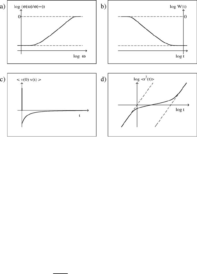
Fig. 21.7. Schematic plot of relevant functions. (a) Normalised frequency-
dependent conductivity caused by the hopping motion of the ions, versus angular
frequency in a log-log representation. (b) Time-dependent correlation factor versus
time in a log-log representation. (c) Velocity autocorrelation function of the mobile
ions versus time. (d) Mean square displacement of the mobile ions versus time in a
log-log representation.
Only at much longer times, when v(0)v(t) becomes very small and, conse-
quently, W (t) tends to its long-time limit, W (∞), does r
2
(t) change from its
subdiffusive behaviour into its diffusive long-time behaviour, which is linear
in time, with r
2
(t) =6Dt,whereD is the coefficient of self-diffusion. Note
that σ(ν)/σ(∞)andW(t), in log-log representations, are almost perfect mir-
ror images of each other, see Fig. 21.7 (a) and Fig. 21.7 (b) as well as Fig. 21.8.
Although this approximate symmetry is useful for practical purposes, we will
not use it for deriving model spectra, σ(ν)/σ(∞). Rather, exploiting the re-
lationships between σ(ν)andv(0)v(t), and between v(0)v(t) and W (t),
we write
σ(ν)
σ(∞)
=1+
∞
0
˙
W (t)cos(2πνt)dt. (21.10)
From (21.10) it is evident that σ(ν)/σ(∞) will be known as soon as W (t)
is known. The basic idea of the CMR is now to find W (t)fromsimplerate
equations that describe the development of the ion dynamics with time.
In the following, we present the equations that allow us to determine func-
tions W (t)andσ(ν)/σ(∞). We also present and discuss general features of

21 Concept of Mismatch and Relaxation 869
the conductivity spectra thus obtained, while the explanation of the physical
concept of the model is postponed to Sect. 21.6.
The rate equations used in the CMR are
−˙g(t)=Ag
K
(t) W (t) (21.11)
and
−
˙
W (t)=−BW(t)˙g(t) . (21.12)
These equations contain two time-dependent functions, W (t)andg(t).
Here W (t) is the time-dependent correlation factor, while g(t) is a normalised
mismatch function, see Sect. 21.6. They also contain three parameters, viz.,
A, B and K. The first parameter, A, is an internal frequency which turns out
to be proportional to the high-frequency conductivity, σ(∞). The second pa-
rameter, B, determines the ratio σ(0)/σ(∞)=W (∞)viaW (∞)=exp(−B).
In many cases, W (∞) is found to be Arrhenius activated which implies that
B should be proportional to the inverse temperature, 1/T . In the following
section, see (21.25), we will show that the ratio A/B is not only proportional
to σ(∞) ·T , and hence to the elementary hopping rate of the mobile ions, Γ
0
,
but that A/B and Γ
0
may even be assumed to be identical (at least for the
example studied, within the limits of experimental error). The value of the
third parameter, K, influences the shape of the resulting conductivity spec-
tra in the vicinity of the onset of the dispersion, see the end of this section
as well as the discussion at the end of Sect. 21.6. In glassy and crystalline
electrolytes with high concentrations of mobile ions, K is typically found to
be 2 or close to 2.
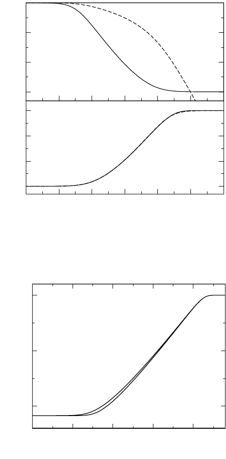
Functions W (t)andg(t) satisfying the rate equations are shown in
Fig. 21.8 (a). The particular parameter values used are W (∞)=0.001 and
K = 2. The time axis has been normalised by multiplication with the internal
frequency A. In a second step, application of (21.10) yields the normalised
conductivity spectrum, σ(ν)/σ(∞), represented in Fig. 21.8 (b) by the solid
line. Note that the broken line in Fig. 21.8 (b), obtained from W (t)byform-
ing the mirror image, provides a good approximation to the exact solution,
i.e.,
σ(ω)
σ(∞)
≈ W
2
πω
. (21.13)
Here, the factor 2/π arises as (21.13) is an approximation for an expres-
sion obtained by Fourier transformation. Figure 21.9 shows the shape of the
frequency-dependent conductivity for a fixed value of B (B = 25), and also
demonstrates the effect of varying the parameter K. In the first place, it is
important to note that, irrespective of the value of K, the model conduc-
tivity spectra do not obey a power law. Rather, as in Fig. 21.6, the appar-
ent slope in the log-log representation increases continuously, approaching
the value of one before the high-frequency plateau is attained. This is the
UDR–NCL transition. Of course, this transition can only be observed, if

870 Klaus Funke, Cornelia Cramer, and Dirk Wilmer
-2 0 2 4 6
-3
-2
-1
0
log
10
W(t), log
10
g(t)
-8 -6 -4 -2 0 2 4
-3
-2
-1
0
log
10
(σ(ω)/σ(∞))
log
10
(t
.
A)
log
10
(ω /A)
W(t)
g(t)
Fig. 21.8. (a) Functions W (t)andg(t) satisfying (21.11) and (21.12) for W (∞)=
exp(−B)=0.001 and K = 2. (b) Solid line: normalised conductivity caused by
hopping motion versus normalised angular frequency as obtained by inserting W (t)
from panel (a) into (21.10). Broken line: mirror-image approximation for the nor-
malised conductivity.
-20 -15 -10 -5 0
log
10
(ω / A)
-10
-5
0
log
10
(σ(ω)/σ(∞))
K = 2.6
K = 2.0
Fig. 21.9. Shape of frequency-dependent conductivity as obtained from the CMR
for fixed B,withB = 25, including the effect of different values of K.

21 Concept of Mismatch and Relaxation 871
W (∞)=σ(0)/σ(∞)=exp(−B) is sufficiently small, i.e., at sufficiently low
temperatures. Otherwise, the high-frequency plateau will be attained before
the transition becomes visible.
Figure 21.9 also shows how the numerical value of K influences the shape
of the spectrum. As K is increased, the transition from σ
dc
= σ(0) into the
dispersive regime becomes more and more gradual. Indeed, such a variation
has been observed experimentally, e.g., upon reducing the number density of
mobile ions in a solid electrolyte [17] or when moving from a binary alkali-ion
conducting glass into the mixed-alkali regime [22,23]. Examples will be given
in Sect. 21.9.
21.5 Scaling Properties of Model Conductivity Spectra
On the basis of (21.11) and (21.12) specific predictions can be made with re-
gard to the behaviour of W(t)andσ(ω)/σ(∞) in the vicinity of those times
and angular frequencies that mark the transitions from σ
dc
into the disper-
sive regime and from the dispersive regime into σ
hf
. We will in particular
show that model conductivity spectra possess the property of scaling in both
limiting cases. This means that the shapes of frequency-dependent model
conductivities are preserved in either frequency regime as the temperature is
varied. Of course, this requires sufficiently large ratios of σ(∞)/σ(0) as well
as a fixed value of the parameter K.
For the purpose of scaling, temperature-dependent angular frequencies
ω
O
and ω
E
will be introduced which mark the onset and the end of the
dispersion, respectively.
The situation is particularly simple at short times, when g(t) is still close
to one, cf. Fig. 21.8 (a). In this case, (21.11) and (21.12) may be combined
and approximated by
−
˙
W (t)=ABW
2
(t) . (21.14)
Equation (21.14) has the solution
W (t)=
1
1+ABt
. (21.15)
This implies that, according to the mirror image approach, the high-frequency
solution for the conductivity should be close to
σ(ω)
σ(∞)
=
1
1+2AB/(πω)
. (21.16)
We may, therefore, somewhat arbitrarily, define an “end angular frequency”
as
ω
E
= AB . (21.17)
Equation (21.16) is remarkable as it describes the nearly-constant-loss be-
haviour encountered at angular frequencies ω below ω
E
,providedg(1/ω)is

872 Klaus Funke, Cornelia Cramer, and Dirk Wilmer
-B
0
2 ln B
ln ( ω
.
B / A
)
-B
0
ln [σ(ω)/σ(∞)]
ω
O
= ⎯
A
B
e
-B
ω
E
= A
.
B
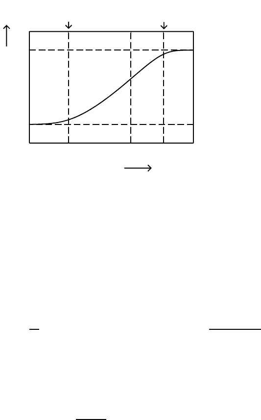
Fig. 21.10. A CMR model conductivity spectrum, with B =8andK =2.The
angular frequencies ω
O
and ω
E
mark the onset and the end of the dispersion.
still close to one. At sufficiently low temperatures, this requirement is indeed
satisfied in a wide range of angular frequencies that are still well below ω
E
.
In Fig. 21.10, the position of ω
E
has been marked in a plot of ln(σ(ω)/σ(∞))
versus ln(ωB/A). The plot also contains a mark for the corresponding “onset
angular frequency”, ω
O
. An expression for ω
O
is obtained by considering low
frequencies, corresponding to long times, where W
scaled
= W (t)/W (∞) tends
to unity. In this case we combine (21.11) and (21.12) to form
−
d
dt
ln W
scaled
(t)=AB exp(−B)W
scaled
(t)
ln W
scaled
(t)
B
K
(21.18)
or, with
ω
O
= AB
1−K
exp(−B) (21.19)
and
t
scaled
= tω
O
, (21.20)
−
d
dt
scaled
ln W
scaled
= W
scaled
· (ln W
scaled
)
K
. (21.21)
Integration of (21.21) yields
t
scaled
=
−ln W (∞)
ln W
scaled
x
−K
e
−x
dx ≈
∞
ln W
scaled
x
−K
e
−x
dx. (21.22)
The approximation made on the right-hand side of (21.22) is always valid
at times that are much longer than 1/ω
E
. In particular, it is always valid in
