Hahn Th. (ed.) International tables for crystallography. Vol. A. Space-group symmetry
Подождите немного. Документ загружается.

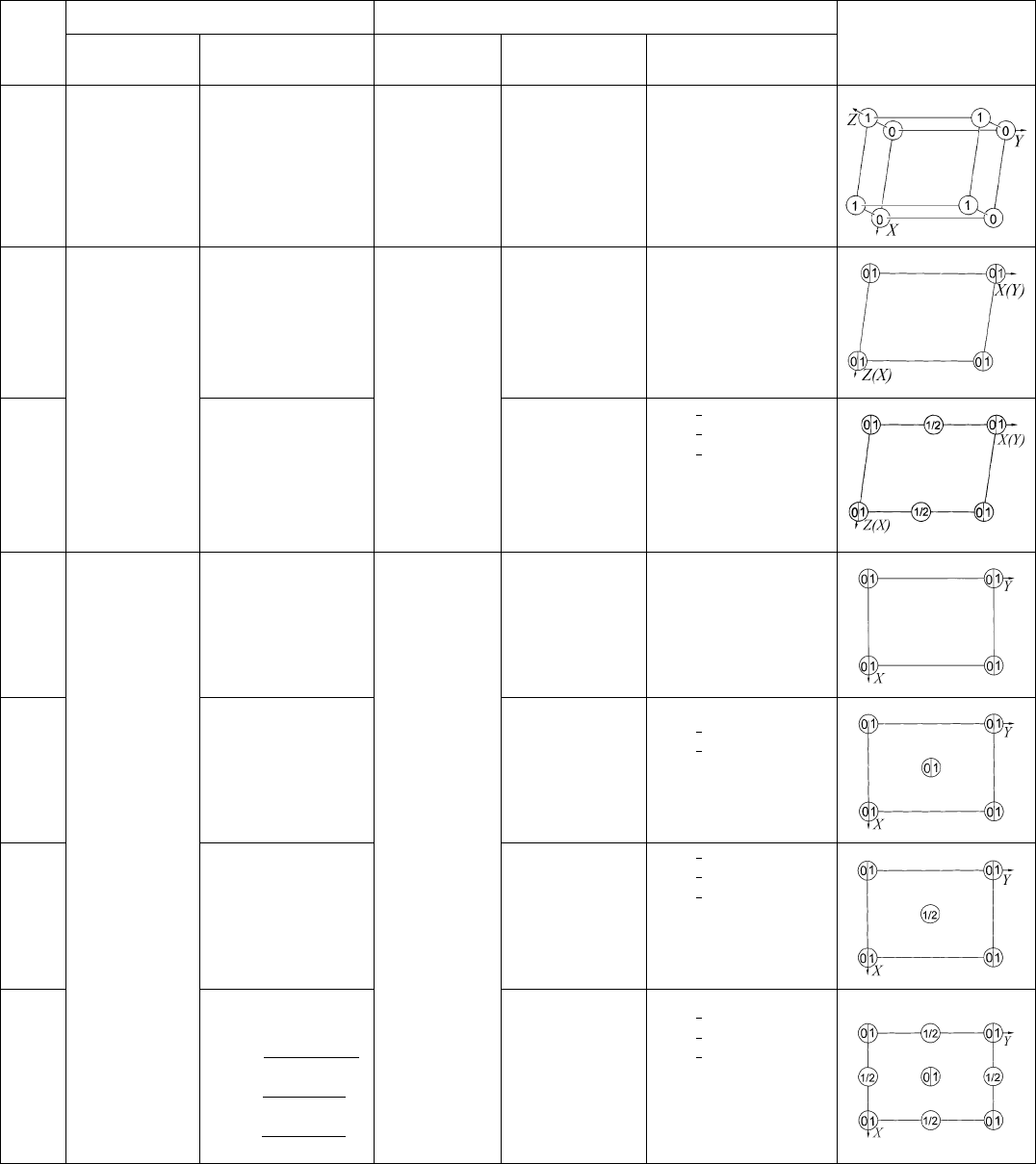
Table 9.1.7.2. Three-dimensional Bravais lattices
Bravais
lattice*
Lattice parameters Metric tensor
Projections
Conventional Primitive Conventional Primitive/transf.y
Relations of the
components
aP
a, b, c
, ,
a, b, c
, ,
g
11
g
12
g
13
g
22
g
23
g
33
g
11
g
12
g
13
g
22
g
23
g
33
mP
a, b, c
, 90
a, b, c
, 90
g
11
0 g
13
g
22
0
g
33
g
11
0 g
13
g
22
0
g
33
mC
mS
a
1
a
2
, c
,
PC
g
0
11
1
4
g
11
g
22
g
0
12
1
4
g
11
g
22
g
0
13
1
2
g
13
g
11
2g
0
11
g
0
12
g
22
2g
0
11
g
0
12
g
13
2g
0
13
g
0
11
g
0
12
g
0
13
g
0
11
g
0
13
g
33
oP
a, b, c
90
a, b, c
90
g
11
00
g
22
0
g
33
g
11
00
g
22
0
g
33
oC
oS
a
1
a
2
, c
, 90
PC
g
0
11
1
4
g
11
g
22
g
0
12
1
4
g
11
g
22
g
11
2g
0
11
g
0
12
g
22
2g
0
11
g
0
12
g
0
11
g
0
12
0
g
0
11
0
g
33
oI
a
1
a
2
a
3
, ,
cos cos
cos 1
PI
g
0
12
1
4
g
11
g
22
g
33
g
0
13
1
4
g
11
g
22
g
33
g
0
23
1
4
g
11
g
22
g
33
g
11
2g
0
12
g
0
13
g
22
2g
0
12
g
0
23
g
33
2g
0
13
g
0
23
~
gg
0
12
g
0
13
~gg
0
23
~g
~
g g
0
12
g
0
13
g
0
23
oF
a, b, c
, ,
cos
a
2
b
2
c
2
2bc
cos
a
2
b
2
c
2
2ac
cos
a
2
b
2
c
2
2ab
PF
g
0
12
1
4
g
33
g
0
13
1
4
g
22
g
0
23
1
4
g
11
g
11
4g
0
23
g
22
4g
0
13
g
33
4g
0
12
~g
1
g
0
12
g
0
13
~
g
2
g
0
23
~
g
3
~
g
1
g
0
12
g
0
13
~g
2
g
0
12
g
0
23
~
g
3
g
0
13
g
0
23
746
9. CRYSTAL LATTICES
Bravais
lattice*
Lattice parameters Metric tensor
Projections
Conventional Primitive Conventional Primitive/transf.y
Relations of the
components
tP
a
1
a
2
, c
90
a
1
a
2
, c
90
g
11
00
g
11
0
g
33
g
11
00
g
11
0
g
33
tI
a
1
a
2
a
3
,
2 cos cos 1
PI
g
0
12
1
4
2g
11
g
33
g
0
13
1
4
g
33
g
11
2g
0
12
g
0
13
g
33
4g
0
13
gg
0
12
g
0
13
gg
0
13
g
g g
0
12
2g
0
13
hR
a
1
a
2
, c
90
120
a
1
a
2
a
3
g
11
1
2
g
11
0
g
11
0
g
33
PR
g
0
11
1
9
3g
11
g
33
g
0
12
1
9
3
2
g
11
g
33
g
11
2g
0
11
g
0
12
g
33
3g
0
11
2g
0
12
g
0
11
g
0
12
g
0
12
g
0
11
g
0
12
g
0
11
hP
a
1
a
2
, c
90
120
g
11
1
2
g
11
0
g
11
0
g
33
cP
a
1
a
2
a
3
90
a
1
a
2
a
3
90
g
11
00
g
11
0
g
11
g
11
00
g
11
0
g
11
cI
a
1
a
2
a
3
109:5
cos
1
3
PI
g
0
11
3
4
g
11
g
11
4
3
g
0
11
g
0
11
1
3
g
0
11
1
3
g
0
11
g
0
11
1
3
g
0
11
g
0
11
cF
a
1
a
2
a
3
60
PF
g
0
11
1
2
g
11
g
11
2g
0
11
g
0
11
1
2
g
0
11
1
2
g
0
11
g
0
11
1
2
g
0
11
g
0
11
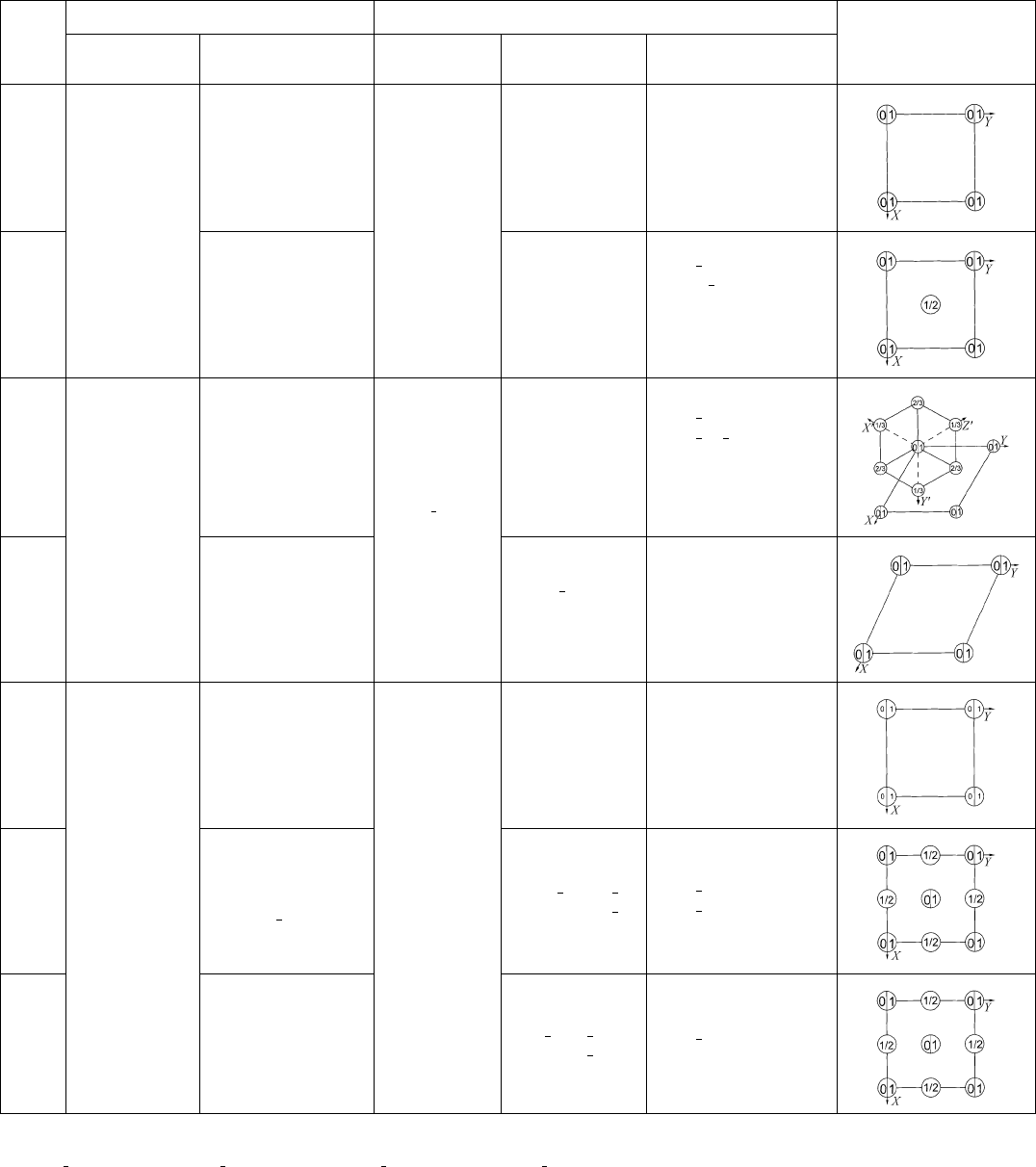
* See footnote to Table 9.1.7.1. Symbols in parentheses are standard symbols, see Table 2.1.2.1.
y PC
1
2
110=
110=002, PI
1
2
1
11=1
11=11
1, PF
1
2
011=101=110, PR
1
3
12
1=
211=111:
Table 9.1.7.2. Three-dimensional Bravais lattices (cont.)
747
9.1. BASES, LATTICES AND BRAVAIS LATTICES

Table 9.1.8.1. The 24 ‘Symmetrische Sorten’
In the centred monoclinic lattices, the set fa, c, a cgfp, q, rg of the three shortest vectors in the ac plane is used to describe the metrical conditions. These
vectors are renamed according to their relation to the projection of the centring point in the ac plane: p designates the vector that crosses the projection of the
centring point, q is the shorter one of the two others and r labels the third one.
Delaunay
symbol Bravais type
Metrical conditions
(parameters of
conventional cells)
Voronoi
type
Notation of the scalar products according to equation
(9.1.8.1)
Transformation
matrix P
12 13 14 23 24 34
K1 cI – I 12 12 12 12 12 12 011=101=110
K2 cF – III 013131313 01
11=111=002
K3 cP –V
0 0 14 14 14 0 100=001=011
0 0 14 0 14 14 100=010=001
HhP– IV 12 0 12 0 12 34 100=010=001
R1 hR 2c
2
< 3a
2
I 121214121414101=
111=0
11
R2 hR 2c
2
> 3a
2
III 013131324 0101=003=012
Q1 tI c
2
< 2a
2
I 121313131312011= 101= 110
Q2 tI c
2
> 2a
2
II 01313131334101=011=002
Q3 tP –V
0 0 14 0 14 34 100=010=001
0 0 14 14 24 0 100=001=011
0 0 14 23 0 23 001=110=010
O1 oF – I 12 13 13 13 13 34 1
11=111=002
O2 oI a
2
b
2
> c
2
I 121314141312011= 101= 110
O3 oI a
2
b
2
< c
2
II 01313232334101=011=002
O4 oI a
2
b
2
c
2
III
013141413 0011=101=110
013132323 0101=011=002
O5 o(AB)C –IV
12 0 14 0 12 34 200=110=001
12 0 14 0 14 34 110=
110=001
O6 oP –V
0 0 14 0 24 34 100=010=001
0 0 14 23 24 0 100=001=011
M1 m(AC)Ib
2
> p
2
I 121314131434
110=
1
10=
101
M2 m(AC)Ip
2
> b
2
> r
2
q
2
I 12131414133401
1=110=10
1
M3 m(AC)Ir
2
q
2
> b
2
II 01314232334
101=
110=
200
M4 m(AC)Ib
2
p
2
II
0131414133401
1=110=10
1
01314131434
110=
1
10=
101
M5 m(AC)Ib
2
r
2
q
2
III
013142323 0
101=
110=
200
013142313 010
1=1
10=0
1
1
M6 mP – IV 0 13 14 0 24 34 100=010=001
T1 aP – I 12 13 14 23 24 34 100=010=001
T2 aP – II 0 13 14 23 24 34 100= 010= 001
T3 aP – III 013142324 0100=010=001
748
9. CRYSTAL LATTICES

are considered. The reduction is performed minimizing the sum
P
b
1
2
... b
n1
2
: 9:1:8:1
It can be shown that this sum can be reduced as long as one of the
scalar products is still positive. If e.g. the scalar product b
1
b
2
is
still positive, a transformation can be performed such that the sum
P
0
of the transformed b
0
2
i
is smaller than
P
:
b
0
1
b
1
, b
0
2
b
2
, b
0
3
b
1
b
3
and b
0
4
b
1
b
4
:
In the two-dimensional case, b
0
3
2b
1
b
3
holds.
If all the scalar products are less than or equal to zero, the three
shortest vectors forming the reduced basis are contained in the set
V fb
1
, b
2
, b
3
, b
4
, b
1
b
2
, b
2
b
3
, b
3
b
1
g,
which corresponds to the maximal set of faces of the Dirichlet
domain (14 faces).
For practical application, it is useful to classify the patterns of the
resulting nn 1=2 scalar products regarding their equivalence or
zero values. These classes of patterns correspond to the reduced
bases and result in ‘Symmetrische Sorten’ (Delaunay, 1933) that
lead directly to the conventional crystallographic cells by fixed
transformations (cf. Patterson & Love, 1957; Burzlaff & Zimmer-
mann, 1993). Table 9.1.8.1 gives the list of the 24 ‘symmetrische
Sorten’. Column 1 contains Delaunay’s symbols, column 2 the
symbol of the Bravais type. For monoclinic centred lattices, the
matrix P of the last column transforms the primitive reduced cell
into an I-centred cell, which has to be transformed to A or C
according to the monoclinic standardization rules, if necessary. P
operates on the basis in the following form:
a
r
, b
r
, c
r
P a
c
, b
c
, c
c
,
where a
r
, b
r
, c
r
denotes the 1 3 matrix of the basis vectors of
the reduced cell and a
c
, b
c
, c
c
the 1 3 matrix of the
conventional cell.
Column 3 gives metrical conditions for the occurrence of certain
Voronoi types. Column 5 indicates the relations among the scalar
products of the reduced vector set. In some cases, different Selling
patterns are given for one ‘symmetrische Sorte’. This procedure
avoids a final reduction step (cf. Patterson & Love, 1957) and
simplifies the computational treatment significantly. The number of
‘symmetrische Sorten’, and thus the number of transformations
which have to be applied, is smaller than the number of lattice
characters according to Niggli. Note that the introduction of
reduced bases using shortest lattice vectors causes complications
in more than three dimensions (cf. Schwarzenberger, 1980).
9.1.9. Example
This example is discussed in Aza´roff & Buerger (1958, pp. 176–
180).
The lattice parameters are given as b
1
4:693, b
2
4:936,
b
3
7:524 A
,
23
131:00,
31
89:57,
12
90:67
. The
scalar products resulting from these data are given in Table 9.1.9.1.
The scalar product b
1
b
3
is positive. Thus the transformation
b
0
1
b
1
, b
0
3
b
3
, b
0
2
b
1
b
2
, b
0
4
b
1
b
4
is applied. The new scalar products are all non-positive as given in
the second row of Table 9.1.9.1 (within the accuracy of the
experimental data). Comparison with Table 9.1.8.1 leads to M6,
Voronoi type IV and the monoclinic Bravais lattice mP .
The transformation related to this case leads to a monoclinic
conventional cell but does not consider the possibility of shorter
basis vectors. For this reason, it is necessary here to look at the
other vectors of the set V in the (b
0
1
b
0
3
) plane, the only one of
interest is b
0
1
b
0
3
. The length of this vector is 4:936 A
, which is
shorter than b
0
3
(jb
0
3
j6:771 A
) and leads to the cell parameters
a 4:693, b 5:678, c 4:936 A
, 90, 90:67, 90
.
Table 9.1.9.1. Example
Transformation
Scalar products
12 13 14 23 24 34
b
1
b
2
b
3
b
4
0:271 0.265 22.02 24.37 0.272 32.51
b
1
b
1
+ b
2
b
3
b
1
+ b
4
21.75 0.265 0 24.10 ~0 32.24
b
0
1
b
0
3
b
0
4
b
0
2
13 14 12 34 23 24
749
9.1. BASES, LATTICES AND BRAVAIS LATTICES

9.2. Reduced bases
BY P. M. DE WOLFF
9.2.1. Introduction
Unit cells are usually chosen according to the conventions
mentioned in Chapter 9.1 so one might think that there is no need
for another standard choice. This is not true, however; conventions
based on symmetry do not always permit unambiguous choice of
the unit cell, and unconventional descriptions of a lattice do occur.
They are often chosen for good reasons or they may arise from
experimental limitations such as may occur, for example, in high-
pressure work. So there is a need for normalized descriptions of
crystal lattices.
Accordingly, the reduced basis* (Eisenstein, 1851; Niggli,
1928), which is a primitive basis unique (apart from orientation)
for any given lattice, is at present widely used as a means of
classifying and identifying crystalline materials. A comprehensive
survey of the principles, the techniques and the scope of such
applications is given by Mighell (1976). The present contribution
merely aims at an exposition of the basic concepts and a brief
account of some applications.
The main criterion for the reduced basis is a metric one: choice of
the shortest three non-coplanar lattice vectors as basis vectors.
Therefore, the resulting bases are, in general, widely different from
any symmetry-controlled basis, cf. Chapter 9.1.
9.2.2. Definition
A primitive basis a, b, c is called a ‘reduced basis’ if it is right-
handed and if the components of the metric tensor G (cf. Chapter
9.1)
a abbc c
b cc aa b
9:2:2:1
satisfy the conditions shown below. The matrix (9.2.2.1) for the
reduced basis is called the reduced form.
Because of lattice symmetry there can be two or more possible
orientations of the reduced basis in a given lattice but, apart from
orientation, the reduced basis is unique.
Any basis, reduced or not, determines a unit cell – that is, the
parallelepiped of which the basis vectors are edges. In order to test
whether a given basis is the reduced one, it is convenient first to find
the ‘type’ of the corresponding unit cell. The type of a cell depends
on the sign of
T a bb cc a:
If T > 0, the cell is of type I, if T 0 it is of type II. ‘Type’ is a
property of the cell since T keeps its value when a , b or c is inverted.
Geometrically speaking, such an inversion corresponds to moving
the origin of the basis towards another corner of the cell. Corners
with all three angles acute occur for cells of type I (one opposite
pair, the remaining six corners having one acute and two obtuse
angles). The other alternative, specified by main condition (ii) of
Section 9.2.3, viz all three angles non-acute, occurs for cells of type
II (one or more opposite pairs, the remaining corners having either
one or two acute angles).
The conditions can all be stated analytically in terms of the
components (9.2.2.1), as follows:
(a) Type-I cell
Main conditions:
a a b b c
c; jb cj
1
2
b b; ja cj
1
2
a a;
ja bj
1
2
a a 9:2:2:2a
b c > 0; a c > 0; a b > 0: 9:2:2:2b
Special conditions:
if a a b b then b c a c
if b b c c then a c a b
if b c
1
2
b b then a b 2a c
if a c
1
2
a a then a b 2b c
if a b
1
2
a a then a c 2b c:
9:2:2:3a
9:2:2:3b
9:2:2:3c
9:2:2:3d
9:2:2:3e
(b) Type-II cell
Main conditions:
as 9:2:2:2a9:2:2:4a
jb cjja cjja bj
1
2
a a b b9:2:2:4b
b c 0; a c 0; a b 0: 9:2:2:4c
Special conditions:
if a a b b then jb cjja cj9:2:2:5a
if b b c c then ja cjja bj9:2:2:5b
if jb cj
1
2
b b then a b 0 9:2:2:5c
if ja cj
1
2
a a then a b 0 9:2:2:5d
if ja bj
1
2
a a then a c 0 9:2:2:5e
if jb cjja cjja bj
1
2
a a b b
then a a 2ja cjja bj: 9:2:2:5f
The geometrical interpretation in the following sections is given in
order to make the above conditions more explicit rather than to
replace them, since the analytical form is obviously the most
suitable one for actual verification.
9.2.3. Main conditions
The main conditions† express the following two requirements:
(i) Of all lattice vectors, none is shorter than a; of those not
directed along a, none is shorter than b; of those not lying in the ab
plane, none is shorter than c. This requirement is expressed
analytically by (9.2.2.2a), and for type-II cells by (9.2.2.4b),
which for type-I cells is redundant.
(ii) The three angles between basis vectors are either all acute or
all non-acute, conditions (9.2.2.2b) and (9.2.2.4c). As shown in
Section 9.2.2 for a given unit cell, the origin corner can always be
*
Very often, the term ‘reduced cell’ is used to indicate this normalized lattice
description. To avoid confusion, we shall use ‘reduced basis’, since it is actually a
basis and some of the criteria are related precisely to the difference between unit
cells and vector bases.
{
In a book on reduced cells and on retrieval of symmetry information from lattice
parameters, Gruber (1978) reformulated the main condition (i) as a minimum
condition on the sum s a b c. He also examined the surface areas of primitive
unit cells in a given lattice, which are easily shown to be proportional to the
corresponding sums s
a
b
c
for the reciprocal bases. He finds that if there
are two or more non-congruent cells with minimum s (‘Buerger cells’), these cells
always have different values of s
. Gruber (1989) proposes a new criterion to
replace the conditions (9.2.2.2a)–(9.2.2.5f ), viz that, among the cells with the
minimum s value, the one with the smallest value of s
be chosen (which need not be
the absolute minimum of s
since that may occur for cells that are not Buerger cells).
The analytic form of this criterion is identical to (9.2.2.2a)–(9.2.2.5e); only
(9.2.2.5f ) is altered. For further details, see Chapter 9.3.
750
International Tables for Crystallography (2006). Vol. A, Chapter 9.2, pp. 750–755.
Copyright © 2006 International Union of Crystallography
chosen so as to satisfy either the first alternative of this condition (if
the cell is of type I) or the second (if the cell is of type II).
Condition (i) is by far the most essential one. It uniquely defines
the lengths a, b and c, and limits the angles to the range
60 , , 120
. However, there are often different unit cells
satisfying (i), cf. Gruber (1973). In order to find the reduced basis,
starting from an arbitrary one given by its matrix (9.2.2.1), one can:
(a) find some basis satisfying (i) and (ii) and if necessary modify it
so as to fulfil the special conditions as well; (b) find all bases
satisfying (i) and (ii) and test them one by one with regard to the
special conditions until the reduced form is found. Method (a) relies
mainly on an algorithm by Buerger (1957, 1960), cf. also Mighell
(1976). Method (b) stems from a theorem and an algorithm, both
derived by Delaunay (1933); the theorem states that the desired
basis vectors a, b and c are among seven (or fewer) vectors – the
distance vectors between parallel faces of the Voronoi domain –
which follow directly from the algorithm. The method has been
established and an example is given by Delaunay et al. (1973), cf.
Section 9.1.3 where this method is described.
9.2.4. Special conditions
For a given lattice, the main condition (i) defines not only the
lengths a, b, c of the reduced basis vectors but also the plane
containing a and b, in the sense that departures from special
conditions can be repaired by transformations which do not change
this plane. An exception can occur when b c; then such
transformations must be supplemented by interchange(s) of b and
c whenever either (9.2.2.3b) or (9.2.2.5b) is not fulfilled. All the
other conditions can be conveniently illustrated by projections of
part of the lattice onto the ab plane as shown in Figs. 9.2.4.1 to
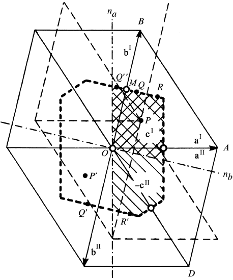
9.2.4.5. Let us represent the vector lattice by a point lattice. In Fig.
9.2.4.1, the net in the ab plane (of which OBAD is a primitive mesh;
OA a, OB b) is shown as well as the projection (normal to that
plane) of the adjoining layer which is assumed to lie above the
paper. In general, just one lattice node P
0
of that layer, projected in
Fig. 9.2.4.1 as P, will be closer to the origin than all others. Then the
vector OP
0
!
is c according to condition (i). It should be stressed
that, though the ab plane is most often (see above) correctly
established by (i), the vectors a, b and c still have to be chosen so as
to comply with (ii), with the special conditions, and with right-
handedness. The result will depend on the position of P with respect
to the net. This dependence will now be investigated.
The inner hexagon shown, which is the two-dimensional Voronoi
domain around O, limits the possible projected positions P of P
0
.Its
short edges, normal to OD, result from (9.2.2.4b); the other edges
from (9.2.2.2a). If the spacing d between ab net planes is smaller
than b, the region allowed for P is moreover limited inwardly by the
circle around O with radius b
2
d
2
1=2
, corresponding to the
projection of points P
0
for which OP
0
c b. The case c b has
been dealt with, so in order to simplify the drawings we shall
assume d > b. Then, for a given value of d, each point within the
above-mentioned hexagonal domain, regarded as the projection of a
lattice node P
0
in the next layer, completely defines a lattice based
on OA
!
, OB
!
and OP
!
0
. Diametrically opposite points like P and P
0
represent the same lattice in two orientations differing by a rotation
of 180
in the plane of the figure. Therefore, the systematics of
reduced bases can be shown completely in just half the domain. As a
halving line, the n
a
normal to OA is chosen. This is an important
boundary in view of condition (ii), since it separates points P for
which the angle between OP
0
and OA is acute from those for which
it is obtuse.
Similarly, n
b
, normal to OB, separates the sharp and obtuse
values of the angles P
0
OB. It follows that if P lies in the obtuse
sector (cross-hatched area) between n
a
and n
b
, the reduced cell is of
type I, with basis vectors a
I
, b
I
, and OP
0
c. Otherwise (hatched
area), we have a type-II reduced cell, with OP
0
c and a and
b as shown by a
II
and b
II
.
Since type II includes the case of right angles, the borders of this
region on n
a
and n
b
are inclusive. Other borderline cases are points
like R and R
0
, separated by b and thus describing the same lattice.
By condition (9.2.2.5c) the reduced cell for such cases is excluded
from type II (except for rectangular a, b nets, cf. Fig. 9.2.4.2); so the
projection of c points to R, not R
0
. Accordingly, this part of the
border is inclusive for the type-I region and exclusive (at R
0
) for the
type-II region as indicated in Fig. 9.2.4.3. Similarly, (9.2.2.5d)
defines which part of the border normal to OA is inclusive.
The inclusive border is seen to end where it crosses OA, OB or
OD. This is prescribed by the conditions (9.2.2.3d), (9.2.2.3c) and
(9.2.2.5f ), respectively. The explanation is given in Fig. 9.2.4.1 for
(9.2.2.3c): The points Q and Q
00
represent the same lattice because
Q
0
(diametrically equivalent to Q as shown before) is separated
from Q
00
by the vector b. Hence, the point M halfway between O and
B is a twofold rotation point just like O. For a primitive orthogonal
a, b net, only type II occurs according to (9.2.2.5c) and (9.2.2.5d),
cf. Fig. 9.2.4.2. A centred orthogonal a, b net of elongated character
(shortest net vector in a symmetry direction, cf. Section 9.2.5) is
depicted in Fig. 9.2.4.4. It yields type-I cells except when 90
[condition (9.2.2.5c)]. Moreover, (9.2.2.3c) eliminates part of the
type-I region as compared to Fig. 9.2.4.3. Finally, a centred net with
compressed character (shortest two net vectors equal in length)
requires criteria allowing unambiguous designation of a and b.
Fig. 9.2.4.1. The net of lattice points in the plane of the reduced basis
vectors a and b; OBAD is a primitive mesh. The actual choice of a and b
depends on the position of the point P, which is the projection of the
point P
0
in the next layer (supposed to lie above the paper, thin dashed
lines) closest to O. Hence, P is confined to the Voronoi domain (dashed
hexagon) around O. For a given interlayer distance, P defines the
complete lattice. In that sense, P and P
0
represent identical lattices; so do
Q, Q
0
and Q
00
, and also R and R
0
. When P lies in a region marked c
II
(hatched), the reduced type-II basis is formed by a
II
, b
II
and c OP
!
0
.
Regions marked c
I
(cross-hatched) have the reduced type-I basis a
I
, b
I
and c OP
!
0
. Small circles in O, M etc. indicate twofold rotation
points lying on the region borders (see text).
751
9.2. REDUCED BASES
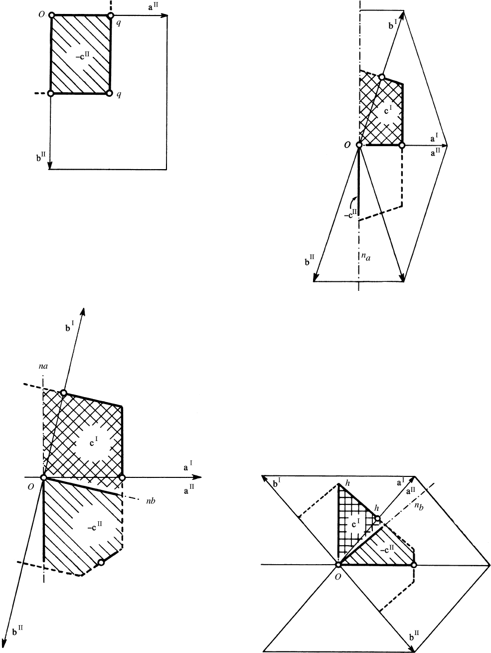
Fig. 9.2.4.3. The effect of the special conditions. Border lines of type-I and
type-II regions are drawn as heavy lines if included. Type-I and type-II
regions are marked as in Fig. 9.2.4.1. n
b
belongs to the type-II region. A
heavy border line of a region stops short of an end point if the latter is
not included in the region to which the border belongs. a, b net oblique;
special conditions (9.2.2.3c), (9.2.2.3d), (9.2.2.5f ).
Fig. 9.2.4.4. The effect of the special conditions. Border lines of type-I and
type-II regions are drawn as heavy lines if included. The type-I region is
cross-hatched; the type-II region is a mere line. A heavy border line of a
region stops short of an end point if the latter is not included in the
region to which the border belongs. a, b net centred orthogonal
(elongated); special conditions (9.2.2.3e), (9.2.2.5e).
Fig. 9.2.4.5. The effect of the special conditions. Border lines of type-I and
type-II regions are drawn as heavy lines if included. Type-I and type-II
regions are marked as in Fig. 9.2.4.1. n
b
belongs to the type-II region. A
heavy border line of a region stops short of an end point if the latter is
not included in the region to which the border belongs. a, b net centred
orthogonal (compressed); special conditions (9.2.2.3a), (9.2.2.5a).
Fig. 9.2.4.2. The effect of the special conditions. Border lines of type-I and
type-II regions are drawn as heavy lines if included. The type-I and
type-II regions are marked as in Fig. 9.2.4.1. A heavy border line of a
region stops short of an end point if the latter is not included in the
region to which the border belongs. a, b net primitive orthogonal;
special conditions (9.2.2.5c), (9.2.2.5d).
752
9. CRYSTAL LATTICES

Table 9.2.5.1. The parameters D b c,E a c and F a b of the 44 lattice characters (A a a, B b b, C c c)
The character of a lattice given by its reduced form (9.2.2.1) is the first one that agrees when the 44 entries are compared with that reduced form in the sequence given below
(suggested by Gruber). Such a logical order is not always obeyed by the widely used character numbers (first column), which therefore show some reversals, e.g. 4 and 5.
No. Type DEFLattice symmetry
Bravais
type‡
Transformation to a conventional basis
(cf. Table 9.2.5.2, footnote **)
A B C
1I A=2 A=2 A=2 Cubic cF 1
11=11
1=
111
2I DDDRhombohedral hR 1
10=
101=
1
1
1
3 II 0 0 0 Cubic cP 100=010=001
5II A= 3 A=3 A=3 Cubic cI 101=110=011
4II DDDRhombohedral hR 1
10=
101=
1
1
1
6II D* DFTetragonal tI
011=101=110
7II D* EETetragonal tI 101=110=011
8II D* EFOrthorhombic oI
1
10=
10
1=0
1
1
A B, no conditions on C
9I A=2 A=2 A=2 Rhombohedral hR 100=
110=
1
13
10 I DDFMonoclinic mC 110=1
10=00
1
11 II 0 0 0 Tetragonal tP 100=010=001
12 II 0 0 A=2 Hexagonal hP 100=010=001
13 II 0 0 F Orthorhombic oC 110=
110
=001
15 II A=2 A=2 0 Tetragonal tI 100=010=112
16 II D* DFOrthorhombic oF
1
10=1
10=112
14 II DDFMonoclinic mC 110=
110=001
17 II D* EFMonoclinic mC 1
10=110=
10
1
B C, no conditions on A
18 I A=4 A=2 A=2 Tetragonal tI 0
11=1
1
1=100
19 I DA/2 A/2 Orthorhombic oI
100=0
11=
111
20 I DEEMonoclinic mC 011= 01
1=
100
21 II 0 0 0 Tetragonal tP 010=001=100
22 II B=2 0 0 Hexagonal hP 010=001=100
23 II D 0 0 Orthorhombic oC 011=0
11=100
24 II D* A=3 A=3 Rhombohedral hR 121=0
11=100
25 II DEEMonoclinic mC 011=0
11=100
No conditions on A, B, C
26 I A=4 A=2 A=2 Orthorhombic oF 100=
120=
102
27 I DA=2 A=
2 Monoclinic mC
120=
100=0
11
28 I DA=22D Monoclinic mC
100=
102=010
29 I D 2DA=2 Monoclinic mC 100=1
20=00
1
30 I B=2 E 2E Monoclinic mC 010=01
2=
100
31 I DEFTriclinic aP 100=010=001
32 II 0 0 0 Orthorhombic oP 100=010=001
40 II B=2 0 0 Orthorhombic oC 0
10=012=
100
35 II D 0 0 Monoclinic mP 0
10=
100=00
1
36 II 0 A=2 0 Orthorhombic oC 100=
10
2=010
33 II 0 E 0 Monoclinic mP 100=010=001
38 II 0 0 A=2 Orthorhombic oC
100=120=00
1
34 II 0 0 F Monoclinic mP
100=00
1=0
10
42 II B=2 A=2 0 Orthorhombic oI
100=0
10=112
41 II B=2 E 0 Monoclinic mC 0
1
2=0
10=
100
37 II D A=2 0 Monoclinic mC 102=100=
010
39 II D 0 A=2 Monoclinic mC
1
20=
100=00
1
43 II D† EFMonoclinic mI
100=
1
1
2=0
10
44 II DEFTriclinic aP 100=010=001
*2jD E FjA B.
† As footnote * plus j2D FjB.
‡ For symbols for Bravais types see footnote * to Table 9.1.7.1 and de Wolff et al. (1985). The capital letter of the symbols in this column indicates the centring type of the
cell as obtained by the transformation in the last column. For this reason, the standard symbols mS and oS are not used here.
753
9.2. REDUCED BASES

These are conditions (9.2.2.3a) and (9.2.2.5a), cf. Fig. 9.2.4.5. The
simplicity of these bisecting conditions, similar to those for the case
b c mentioned initially, is apparent from that figure when
compared with Fig. 9.2.4.3. This compressed type of centred
orthogonal a, b net is limited by the case of a hexagonal net (where
it merges with the elongated type, Fig. 9.2.4.4) and by the centred
quadratic net (where it merges with the primitive orthogonal net,
Fig. 9.2.4.2). In the limit of the hexagonal net, the triangle Ohh in
Figs. 9.2.4.4 and 9.2.4.5 is all that remains, it is of type I except for
the point O. For the quadratic net, only the type-II region in Fig.
9.2.4.5, then a triangle with all edges inclusive, is left. It
corresponds to the triangle Oqq in Fig. 9.2.4.2.
9.2.5. Lattice characters
Apart from being unique, the reduced cell has the further advantage
of allowing a much finer differentiation between types of lattices
than is given by the Bravais types. For two-dimensional lattices, this
is apparent already in the last section where the centred orthogonal
class is subdivided into nets with elongated character and those with
compressed character, depending on whether the shortest net vector
is, or is not, a symmetry direction. It is impossible to perform a
continuous deformation – within the centred orthogonal type – of an
elongated net into a compressed one, since one has to pass through
either a hexagonal or a quadratic net.
In three dimensions, lattices are of the same character if, first, a
continuous deformation of one into the other is possible without
leaving the Bravais type. Secondly, it is required that all matrix
elements of the reduced form (9.2.2.1) change continuously during
such a deformation. These criteria lead to 44 different lattice
characters (Niggli, 1928; Buerger, 1957). Each of them can be
recognized easily from the relations between the elements of the
reduced form given in Table 9.2.5.1 [adapted from Table 5.1.3.1 in
IT (1969), which was recently improved by Mighell & Rodgers
(1980)]. The numbers in column 1 of this table are at the same time
used as a general notation of the lattice characters themselves. We
speak, for example, about the lattice character No. 7 (which is part
of the Bravais type tI) etc.
In Table 9.2.5.2, another description of lattice characters is given
by grouping together all characters of a given Bravais type and by
indicating for each character the corresponding interval of values of
a suitable parameter p, expressed in the usual parameters of a
Table 9.2.5.2. Lattice characters described by relations between conventional cell parameters
Under each of the roman numerals below ‘Lattice characters in’, numbers of characters (cf. Table 9.2.5.1, first column) are listed for which the key parameter p lies in the
interval defined by the same roman numeral below ‘Intervals of p’. For instance, a lattice with character No. 15 under IV has p c=a; so it falls in the interval IV with
p
2 < c=a < 1; No. 33 under II has p b; therefore the interval a c for II yields the relation a < b < c.
Lattice symmetry
Bravais
type*
p key
parameter
Lattice characters in Intervals of p
Conventions**I II III IV I II III IV
Tetragonal tP c=a 21 11 – – 0 1 1 ––
Tetragonal tI c=a 18 6 7 15 0
p
2=3 1
p
2 1
Hexagonal hP c=a 22 12 – – 0 1 1 ––
Rhombohedral hR c =a 24 4 2 9 0
p
3=8
p
3=2
p
6 1 Hexagonal axes
Orthorhombic oP – 32 no relations – – – – – a < b < c
Orthorhombic oS
b < a=
p
3 c 23 13 – – 0 d† 1 ––a < b
b > a=
p
3 c 40 36 38 – 0 ad† 1 –
Orthorhombic oI r‡ 8 19 42 – 0
ab1 – a < b < c
Orthorhombic oF b=a 16 26 – – 1
p
3 1 ––a < b < c
Monoclinic mP b 35 33 34 – 0 ac1 – a < c{
Monoclinic mS
Centred
net
1x
2
2, 3
1, 2, 3
3
8
>
>
>
>
>
>
>
>
>
>
>
>
<
>
>
>
>
>
>
>
>
>
>
>
>
:
b=a
b=a
b=a
b=a
b=a
37
41
n
27
39
n
43
20
10
17
n
25
14
28
29
n
30
9
>
>
>
>
>
>
>
>
=
>
>
>
>
>
>
>
>
;
0
1
p
1=3
1
1
p
3
1
C centred{
I centred{
Triclinic aP , , 31 44 – – 60
90
120
––a < b < c
Cubic
cP
cI
cF
3
5
1
9
=
;
no relations
* For symbols for Bravais types see footnote * to Table 9.1.7.1 and de Wolff et al. (1985).
† d
1
2
p
a
2
b
2
.
‡ r
1
2
p
a
2
b
2
c
2
.
§ This number specifies the centred net among the three orthogonal nets parallel to the twofold axis and passing through (1) the shortest, (2) the second shortest, and (3) the
third shortest lattice vector perpendicular to the axis. For example, ‘2, 3’ means that either net (2) or net (3) is the centred one.
{ Setting with unique axis b; >90
; a < c for both P and I cells, a < c or a > c for C cells.
** These conventions refer to the cells obtained by the transformations of Table 9.2.5.1. They have been chosen for convenience in this table.
754
9. CRYSTAL LATTICES
conventional cell. In systems where no generally accepted
convention exists, the choice of this cell has been made for
convenience in the last column of this table.
The subdistinctions ‘centred net 1, 2 or 3’ for the monoclinic
centred type are closely related to the description in other
conventions. For instance, they correspond to C-, A-orI-centred
cells, respectively, if b is the unique axis and a and c are the shortest
vectors a < c perpendicular to b; note that in Table 9.2.5.2 only
C and I, not A, cells are listed. From the multiple entries in Table
9.2.5.2 for this type, it follows that the description in terms of b/a is
not exhaustive; the distinctions depend upon rather intricate
relations (cf. Mighell et al., 1975; Mighell & Rodgers, 1980).
No attempt has been made in Table 9.2.5.2 to specify whether the
end points of p intervals are inclusive or not. For practical purposes,
they can always be taken to be non-inclusive. Indeed, the end points
correspond either to a different Bravais type or to a purely
geometric singularity without physical significance. If p is very
close to an interval limit of the latter kind, one should be aware of
the fact that different measurements of such a lattice may yield
different characters, with totally differing aspects of the reduced
form.
9.2.6. Applications
9.2.6.1. Classification
The reduced basis can be used to derive the Bravais-lattice type
and the conventional cell parameters, starting from an arbitrary
description of the lattice. For this purpose, the reduced form is first
derived from the given description, e.g. by means of the algorithm
of Kr
ˇ
ivy
´
& Gruber (1976). Subsequently it is compared with the
reduced forms (Table 9.2.5.1) for the 44 lattice characters and
transformed to the appropriate conventional cell. Thus the reduced
cell is helpful as an accessory in classifications based on
conventional cells.
Alternatively, the parameters of the reduced form itself (either of
the direct lattice or of the reciprocal lattice) can be used as a basis
for determinative classification.
9.2.6.2. Comparison of lattices
Two lattices, defined by their reduced cells, can be compared on
a rigorous basis to find out whether they are identical lattices or are
related by one cell being a subcell of the other (Santoro et al., 1980).
Further properties of lattices are discussed in Chapter 9.3.
Acknowledgements
The author wishes to thank Dr B. Gruber (Prague) and Dr A.
Santoro (Washington) for reading the manuscript and for suggesting
several improvements as well as pointing out errors, especially in
Tables 9.2.5.1 and 9.2.5.2.
755
9.2. REDUCED BASES
