Groshong Richard H. 3-D Structural Geology(Second Edition)
Подождите немного. Документ загружается.


189
An overturned fold limb can easily be mistaken for a fault zone. The upward and
downward correlations will break down at the axial surfaces that bound the over-
turned limb. The overturned sequence will appear to be an unfamiliar unit and so
is easily interpreted as being a fault zone. Try correlating an upside
-down stratigraphic
column to the possible fault zone to see if an overturned section is present. Beds
near the fault may be steeply dipping, causing a great exaggeration of the bed thick-
nesses in a vertical well, representing another factor to consider when correlating to
the type section.
The precision of the determination of stratigraphic separation depends on the level
of detail to which the stratigraphy is known. For example, if the fault cut in Fig. 7.10a
was at the top of unit e rather than near the base, the missing section would be signifi-
cantly (50–75 m) greater. The error in the amount of missing section is the sum of the
stratigraphic uncertainties in the units on both sides of the fault. Lack of stratigraphic
resolution means that small faults may not be detectable by correlation of sections.
The fault cut refers to the position of the fault in a well and the to the amount of
the missing or repeated section compared to the reference section (Tearpock and
Bischke 2003). The location of the fault cut, the amount of the fault cut and the ref-
erence section should be recorded for each fault cut. It is not unusual to find that after
preliminary mapping has been completed, the original stratigraphic thicknesses were
inappropriate. For example, the units in a reference well may be shown by mapping
to have a significant dip and their thicknesses therefore will have been exaggerated.
Mapping may also reveal that the reference section is faulted. Any change in thick-
ness in the reference section requires changes in the magnitudes of all the fault cuts
determined from it.
Fig. 7.10. Location and amount of stratigraphic separation determined from the missing or repeated
section across the fault. a About 300 m of section is missing across a normal fault. b About 600 m of
section is repeated across a reverse fault
7.2 · Recognition of Faults

190 Chapter 7 · Properties of Faults
7.2.6
Rock Type
Rock types diagnostic of faulting (Fig. 7.11) include the cataclasite suite, produced pri-
marily by fragmentation, and the mylonite suite, produced by large crystal-plastic strains
and/or recrystallization (Sibson 1977; Ramsay and Huber 1987). A cataclastic fault sur-
face, or slickenside, is usually grooved, scratched, or streaked by mineral fibers or may
be highly polished. The parallel striations or mineral elongation directions are slicken-
lines which indicate the slip direction at some stage in the movement history. A mylonite
typically has a thinly laminated compositional foliation and a strong penetrative min-
eral lineation which is elongated in the displacement direction. Soft
-sediment fault
zones typically have macroscopic textures similar to those of mylonite zones, although
no metamorphism has occurred. At the microscopic scale, the grains in a soft
-sedi-
ment fault zone are usually undeformed.
A fault zone may be recognizable in well logs. An uncemented cataclastic fault zone
is mechanically weak and very friable. This is the reason why an outcropping fault zone
may erode to a valley. Where a well encounters a mechanically weak unit, such as an
uncemented fault zone, an enlargement of the well
-bore diameter occurs. A caliper log
is produced by a tool that measures the size of the well bore and a fault may be re-
corded as an expansion in the size of the borehole, generally short in length. Well
enlargement may occur in any mechanically weak unit such as coal, uncemented clay
or sand, salt, etc. If the normal stratigraphic reasons for well enlargement can be elimi-
nated, however, then the presence of a fault zone is a good possibility. A high
-resolu-
tion dipmeter provides a log that resembles a photograph of the wall of the borehole.
A fault zone may be inferred from the same observational criteria that would apply to
Fig. 7.11. Representative fault-rock textures. The scale is approximate. a Cataclasite. b Mylonite. Drawn
from thin section photographs in Ramsay and Huber (1987)

191
an outcrop, in particular, a high concentration of fractures or an abrupt change in li-
thology not part of the normal stratigraphic sequence.
7.2.7
Fault Drag
The systematic variation of the dip of bedding adjacent to the fault shown in Fig. 7.12b
is known as “normal” drag, or simply drag, as the term will be used here. A drag fold
gives the sense of slip on the fault. This geometry is probably best interpreted as being
the result of the permanent strain that occurs prior to faulting (Fig. 7.12a), a sequence
of formation well known from experimental rock mechanics. The term “drag” is thus
a misnomer because the fold forms prior to faulting, not as the result of frictional drag
along a pre
-existing fault. In fact, the strain associated with slip on a pre-existing fault
tends to produce bending in the opposite direction relative to the sense of slip (Reches
and Eidelman 1995) called “reverse” drag. The reverse drag described by Reches and
Eidelman (1995) is significantly smaller in magnitude than the normal drag produced
before faulting and might not be noticeable at the map scale. Map
-scale reverse drag
is also well known as a consequence of slip on a downward
-flattening normal fault
(Hamblin 1965). Because the term drag is long established for the fold close to a fault
and because the curvature of drag folds gives the correct interpretation of the sense of
shear, use of the term is continued here. The drag
-fold geometry usually extends no
more than a few to tens of meters away from the fault zone. Although the drag geom-
etry is common, not all faults have associated drag folds.
7.3
Unconformities
Unconformities are important surfaces for structural and stratigraphic interpretation.
They provide evidence for structural and sea
-level events, and mineral deposits, in-
cluding hydrocarbons, are commonly trapped below unconformities. An unconformity
truncates older geological features and so shares a geometric characteristic with a fault
which also truncates older features (Figs. 7.4 and 7.13). Sometimes the two can be dif-
ficult to distinguish. The flat portion of a fault may cut bedding at a very low angle, just
like the typical unconformity.
Fig. 7.12. Drag folds caused by permanent bending strain before faulting. a Fold before the units reach
their ductile limit. b A fault forms after the ductile limit is exceeded, and the permanent strain remains
as a drag fold
7.3 · Unconformities

192 Chapter 7 · Properties of Faults
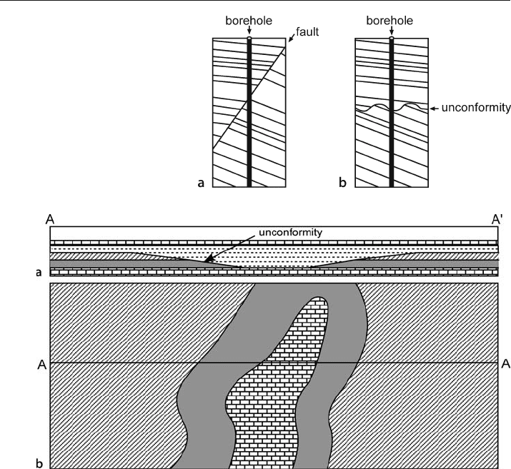
An unconformity can be mapped like a stratigraphic horizon, but it is significantly
different because the units both above and below the unconformity can change over
the map area (Fig. 7.14). An unconformity surface should be mapped separately from
the units that it cuts or that terminate against it. The stratigraphic separation across
an unconformity can be mapped and the separation can be expected to die out later-
ally into a continuous stratigraphic sequence (the correlative conformity) or at an-
other unconformity. A subcrop map shows the units present immediately below an
unconformity (Fig. 7.14b). This type of map has several important uses. It provides a
guide to the paleogeology, can indicate the trends of important units, for example
hydrocarbon reservoirs, and can suggest the paleostructure. An analogous map type
is a subcrop map of the units below a thrust fault.
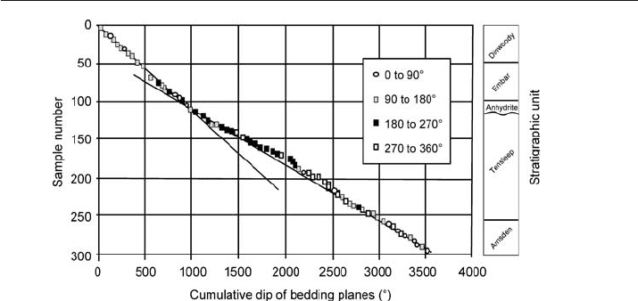
The dip change across an unconformity can be very small, a few degrees or less. A
plot of the cumulative dip versus depth (Hurley 1994) is very sensitive to such small
Fig. 7.13.
A dip change across a strati-
graphic discontinuity may be
either a fault or an uncon-
formity. a Fault. b Unconfor-
mity. (After Hurley 1994)
Fig. 7.14. The geometry of a low-angle unconformity. a Cross section showing a filled paleo-valley.
Vertical exaggeration is about two to three times. b Subcrop map of units below the unconformity.
(After Calvert 1974)

193
changes (Fig. 7.15). The vertical axis can be either depth or the sample number. Equal
spacing of points on the vertical axis gives a more interpretable result and so if the
bedding planes are sampled at irregular intervals, it is better to plot sample number
rather than true depth or distance (Hurley 1994). The dips of the bedding planes are
added together in the direction of the traverse to obtain the cumulative dip. In the
example (Fig. 7.15), the change in average slope of the line through the data points
indicates the position of an unconformity at the top of the Tensleep sandstone. The dip
change in Fig. 7.15 is only 1.3° across the unconformity, yet it is clearly visible.
An additional analysis technique for the cumulative dip data is a first derivative plot
(Hurley 1994). The first derivative (slope) between each two data points is plotted as
the vertical axis and the cumulative dip of bedding planes as the horizontal axis. The
slope between two successive dip points is the difference in depth or the sample
-num-
ber increment (1) divided by the difference in cumulative dip between adjacent samples.
Abrupt dip changes, even small ones, appear as large departures from the overall trend
on this type of plot.
7.4
Displacement
Displacement is the general term for the relative movement of the two sides of a fault,
measured in any direction (Bates and Jackson 1987). The components of displacement
depend on five measurable attributes: the attitude of the fault, the magnitude of the
stratigraphic separation, the attitudes of the beds on both sides of the fault, and direc-
tion of the slip vector in the fault plane. Different sets of these attributes are used to
define the displacement components of slip or separation as will be discussed next.
Throw and heave are the separation components most useful in structure-contour map
construction because they appear on the map.
Fig. 7.15. Cumulative dip versus sample number from a well in the Bighorn basin, western U.S. Samples are
numbered from the top of the well. Bedding planes are derived from a high-resolution dipmeter log. Points
falling into different quadrants of the compass are coded with different symbols. (After Hurley 1994)
7.4 · Displacement

194 Chapter 7 · Properties of Faults
7.4.1
Slip
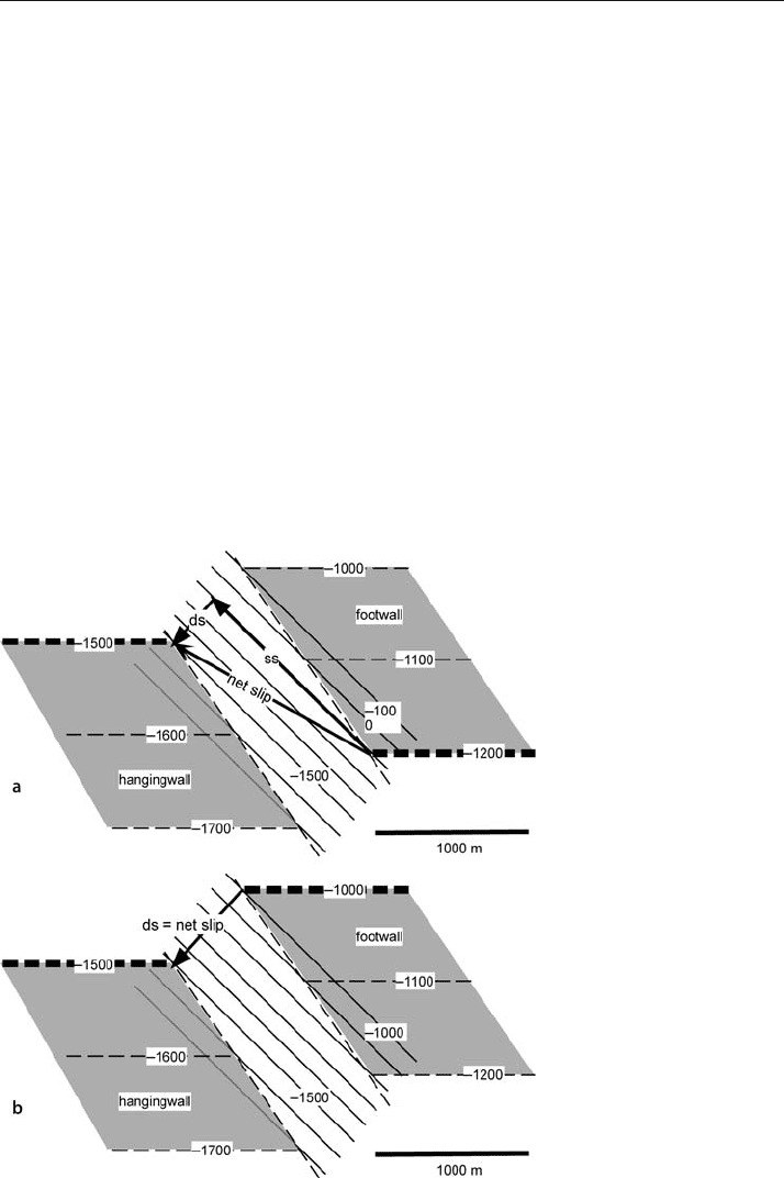
Slip (or net slip) is the relative displacement of formerly adjacent points on opposite
sides of the fault, measured along the fault surface (Bates and Jackson 1987). Slip is
commonly described in terms of its components in the plane of the fault, dip slip and
strike slip (Fig. 7.16a). Dip slip components are normal or reverse and strike slip com-
ponents are right lateral or left lateral. The offset of a marker horizon, as recorded on
a map, can be produced by slip in a variety of directions. The geometry of the fault and
the offset horizon are identical in Figs. 7.16a,b but the fault in 7.16a is oblique slip and
in 7.16b is pure dip slip.
There are two traditional approaches for finding the net slip on a fault. The most
direct is to find the offset of a geological line that can be correlated across the fault. A
geological line may be a geographic or a paleogeographic feature such as a stream
channel or a facies boundary. The alternative is based on the distance in the slip direc-
tion between correlative planar surfaces. In this method the slip direction must be
known, for example, from the slickenline direction. The orientation of the slip vector
may be recorded as the bearing and plunge of the lineation, or as the rake, which is the
angle from horizontal in the plane of the fault.
Fig. 7.16.
Displacement of a marker
horizon (shaded, with dashed
contours) across a fault (un-
shaded, with solid contours).
The final geometries of a and
b are identical although the
slip is different. Wide contour
lines represent correlative lin-
ear features displaced by the
fault. ds: dip slip; ss: strike slip.
a Right-lateral, normal oblique
slip. b Normal dip slip

195
The best features for determining true displacements are the offsets of pre-existing
linear stratigraphic trends or the intersection lines produced by cross
-cutting features,
for example, a dike
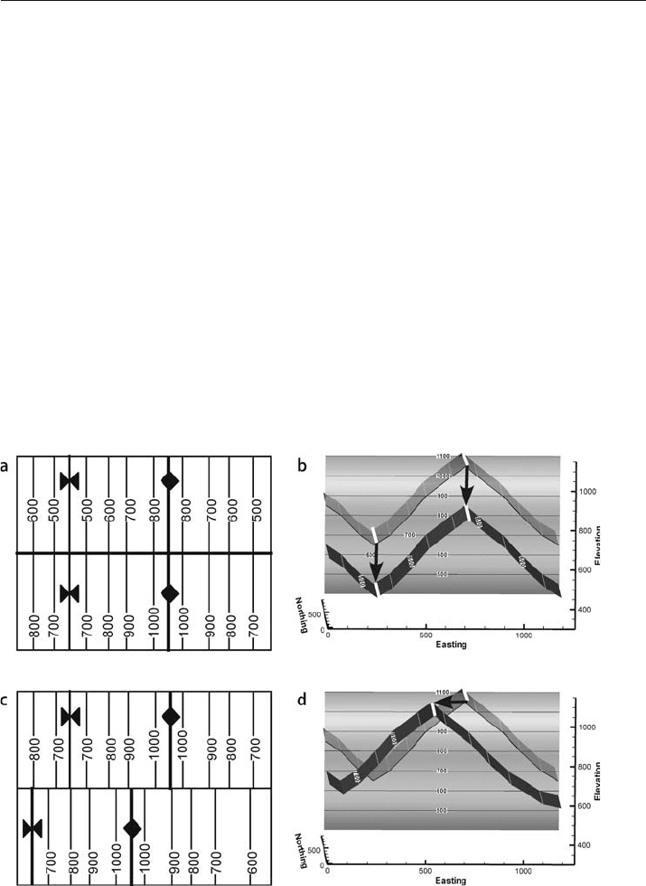
-bedding plane intersection line. Offset structural lines may be used
in some circumstances. Fold hinge lines on identical marker horizons are potentially
correlative marker lines. The offsets of the hinge lines in Fig. 7.17 give the true dis-
placement for both the dip slip and strike slip examples. Offset hinge lines are good
markers of displacement if the folds developed prior to faulting. Tear faults present at
the beginning of folding may divide a region into separate blocks in which the folds
can develop independently. The folds in adjacent blocks may have never been con-
nected and so the separation of their hinge lines is not a measure of the displacement.
If more than one fold hinge line can be matched across the fault and more than one
hinge line gives approximately the same displacement, the probability is higher that
the fault displaces pre
-existing folds and the displacement determination is valid. The
most complete method for the determination of the slip from the offset of geological
features that intersect the fault is based on Allan maps of cutoff lines in the fault sur-
face (see Sect. 8.4.3).
Fault slip can be obtained if marker beds can be matched across the fault in the slip
direction. The slip direction may be given by the direction of grooves or slickenlines
observed on the fault surface or by the trend of the lineation in the fault
-zone rock.
Fig. 7.17. Folds offset by a later fault. a Structure contour map of vertical slip on vertical fault. b Oblique
view to N of 3-D version of a. c Structure contour map of strike-slip on a vertical fault. d Oblique view
to N of 3-D version of c. North-south lines on a and c are structure contours labeled with elevations. White
lines on b and d are fold hinge lines, black arrows are slip vectors, fault is shaded with contours labeled
7.4 · Displacement

196 Chapter 7 · Properties of Faults
The slip direction is usually perpendicular to the axis of the drag fold at the border
of the fault zone, which can be observed in outcrop or be inferred by dip sequence
(SCAT) analysis (Chap. 9, see also Becker 1995). The axes of folds contained within a
fault zone are approximately normal to the slip direction, but may be arcuate, in which
case the slip direction bisects the arc (Hansen 1971). Slip vector determination con-
tains inherent ambiguities that must be considered, however. Different slip directions
may be overprinted with only the last increment being observed or the slip trajecto-
ries may be curved.
To determine the fault slip, draw the slip vector on the structure contour map of the
fault so that it connects the correlated points on the hangingwall and the footwall as
in Fig. 7.16. If the end points of the slip vector are specified by their xyz coordinates,
the length of the slip vector in the plane of the fault is (from Eq. 2.4)
L =[(x
2
– x
1
)
2
+(y
2
– y
1
)
2
+(z
2
– z
1
)
2
]
1/2
, (7.1)
where L = the slip and the subscripts “1” and “2” = the coordinates of the opposite ends
of the slip vector. If the end points are specified by the horizontal and vertical distance
between them (from Eq. 4.7)
L =(v
2
+ h
2
)
1/2
, (7.2)
where L = the slip, v = vertical distance between end points, and h = the horizontal
distance between end points.
Without the information provided by the correlation of formerly adjacent points
across the fault or knowledge of the slip vector, it is impossible to determine whether
a fault is caused by strike slip, dip slip, or oblique slip. Map interpretation must fre-
quently be done without knowledge of the slip amount or direction, a situation for
which the fault separation, given next, provides the framework for the interpretation.
7.4.2
Separation
Separation is the distance between any two index planes disrupted by a fault (Dennis
1967; Bates and Jackson 1987). Several different separation components are commonly
used to describe the magnitude of the fault offset. Strike and dip separations are, re-
spectively, the separations measured between correlative surfaces along the strike and
directly down the dip of the fault (Billings 1972). The stratigraphic separation (Fig. 7.18)
is the stratigraphic thickness of the beds missing or repeated across a fault (after Bates
and Jackson 1987). Stratigraphic separation is a thickness, and therefore represents a
measurement direction perpendicular to bedding. The stratigraphic separation is equal
to the fault cut, that is, the amount of section missing or repeated across a fault at a
point. It is possible for a fault to have a large displacement and yet show no strati-
graphic separation. For example, strike
-slip displacement of horizontal beds produces
no stratigraphic separation. Other combinations of slip direction and dip of marker
beds can also result in zero separation (Redmond 1972).

197
Fig. 7.18.
Vertical and stratigraphic fault
separation. a Reverse fault.
b Normal fault: the marker
horizon must be projected
across the fault in order to
measure the vertical separation
Vertical separation is the distance, measured vertically, between the two parts of
a displaced surface (Fig. 7.18; Dennis 1967). In the case of a normal
-separation fault,
one of the surfaces must be projected across the fault to make the measurement. The
vertical separation of an offset marker horizon is shown in a vertical cross section in
the direction of dip of the bedding across the fault from the fault cut (Fig. 7.19). The
separation is measured from the marker horizon at the point of the fault cut to the
position of the same marker horizon across the fault (reverse separation; Fig. 7.19a)
or from the marker horizon at the fault cut to the projection of the marker horizon
from its location across the fault (normal separation, Fig. 7.19b). The amount of the
vertical separation is
v = t /cos
δ
, (7.3)
where v = vertical separation, t = stratigraphic separation = amount of the fault cut,
and
δ
= cross-fault bedding dip. The cross-fault bedding dip is the dip of bedding across
the fault from the marker horizon at the fault cut. The vertical separation of a vertical
bed is undefined.
7.4 · Displacement

198 Chapter 7 · Properties of Faults
7.4.3
Heave and Throw from Stratigraphic Separation
Heave and throw have a special significance because they are the separation compo-
nents visible on the structure contour map of a faulted horizon. Throw is the vertical
component of the dip separation and heave is the horizontal component of the dip
separation, both being measured in a vertical cross section in the dip direction of the
fault (Dennis 1967; Billings 1972). Throw and heave can be found directly from the
stratigraphic separation. The following discussion refers to the geometry shown in
Fig. 7.20. Let point P
1
be the location of the fault cut in a well or exposed in outcrop.
The marker horizon is shaded. P
2
is the location of the marker horizon in a vertical
plane oriented in the direction of fault dip. The calculation of throw and heave is a
projection across the fault from the control location (P
1
) to a predicted location (P
2
).
The stratigraphic separation at the point of the fault cut is the thickness of the missing
or repeated section, t. The dip separation, S
d
, is equal to the apparent thickness of the
missing or repeated section in the direction of the fault dip (dip vector) between
points P
1
and P
2
. The dip separation can be found from Eq. 4.1 as
S
d
= t /cos
ρ
, (7.4)
where t = the stratigraphic separation and
ρ
= the angle between the pole to the cross-
fault bedding attitude and the dip vector of the fault. The dip of bedding used is always
that belonging the side of the fault to which the projection is being made (P
2
), that is,
across the fault from the fault cut on the marker horizon. The value of
ρ
can be found
with a stereogram (Sect. 4.1.1.1) or from any of the analytical methods in Sect. 4.1.1.2.
The heave and throw are determined by taking the horizontal (H) and vertical (T)
components (Fig. 7.20) of S
d
from Eq. 7.4:
H = t cos
φ
/cos
ρ
, (7.5)
T = t sin
φ
/cos
ρ
, (7.6)
Fig. 7.19. Vertical separation calculated in a vertical cross section in the direction of the cross-fault
bedding dip. a Reverse separation fault. b Normal separation fault
