Gersten J.I., Smith F.W. The Physics and Chemistry of Materials
Подождите немного. Документ загружается.


292 OPTICAL MATERIALS
The Verdet constant is therefore
V D
e
m
c
c
ω
ω
p
2
1
r
0
2
p
r
0
³
ne
3
m
2
c
c
0
ω
2
ω
2
ω
2
0
3/2
ω
2
ω
2
0
ω
2
p
,W18.21
where the damping constant is neglected in the last expression.
This formula displays the factors influencing the size of the Verdet constant: the
concentration of oscillators, the cyclotron effective mass of the carriers, and the reso-
nance frequency relative to that of the light. In semiconductors, the effective mass
could be small and the value of V could be large. In the neighborhood of an electronic
resonance, the value of V could likewise become large.
Typical values for the Verdet constant for several nonmagnetic materials are presented
in Table W18.1. It is customary to express V in arc-minutes/OeÐm, where 1 Oe D
1, 000/40 A/m. A magnetic induction of B D 40 ð 10
7
T corresponds to a field
intensity H of 1 A/m. The Faraday and Kerr effects in magnetic materials are discussed
in Chapter 17 of the textbook.
†
Magneto-optical applications are also given there.
An optical isolator may be constructed from a polarizer and Faraday rotator that
rotates the polarization vector by 45
°
. If light is partially reflected from some interface
TABLE W18.1 Verdet Constants for Several Non-
magnetic Materials
$V
Material (nm) (arc-min/OeÐm)
Diamond 589.3 2.3
NaCl 589.3 3.5
KCl 589.3 2.8
SiO
2
589.3 1.7
B
2
O
3
633 1.0
Al
2
O
3
546.1 2.4
SrTiO
3
620 14
ZnSe 476 150
496 104
514 84
587 53
633 41
Tb
2
Al
5
O
12
520 103.9 (300 K)
520 343 (77 K)
520 6480 (4.2 K)
KH
2
PO
4
(KDP) 632.8 1.24
Source: Data from M. J. Weber, Handbook of Laser Science and
Technology, Vol. 4, CRC Press, Boca Raton, Fla., 1986; and
D. R. Lide, ed., CRC Handbook of Chemistry and Physics, 75th
ed., CRC Press, Boca Raton, Fla., 1994.
†
The material on this home pate is supplemental to The Physics and Chemistry of Materials by Joel I.
Gersten and Frederick W. Smith. Cross-references to material herein are prefixed by a “W”; cross-references
to material in the textbook appear without the “W.”
OPTICAL MATERIALS 293
after it passes through the isolator, the direction of its electric field vector will be
reversed by the reflection. As it propagates backward through the Faraday rotator, the
electric field vector will experience a further 45
o
rotation. Since the field will then be
perpendicular to the polarizer, it will be blocked by it. This prevents the reflected light
from propagating backward and possibly causing damage to optical components.
W18.3 Theory of Optical Band Structure
Band-structure engineering may be applied to more complex structures than were
considered in Section 18.6. In this section an analysis is given of one such structure,
consisting of a one-dimensional periodic array. Each unit cell of the array contains
two layers of transparent material with different indices of refraction. The propagation
of electron waves in one-dimensional periodic structures is studied in Chapter 7, and
it forms the basis for understanding the band theory of solids. Here the concept is
extended to the optical case.
Consider the passage of light through two materials in the case where the photon
energy is less than the bandgap. Barring any other absorption processes, both materials
would, separately, be transparent. Next construct a stratified structure in which alternate
layers of the two materials are stacked in a periodic fashion. It will be shown that for
some wavelengths, propagation cannot occur and the structure acts as a mirror. Other
colors, however, will pass through and the structure therefore acts as a color-selective
filter. These effects come about due to the destructive and constructive interference of
reflected light waves, in much the same way as electronic band structure results from
the interference of scattered electron waves in solids.
Let the indices of refraction for the two materials be n
1
and n
2
, and let the thick-
ness of layer n
1
be b and the thickness of layer n
2
be a b. The structure has a
periodicity of size a (Fig. W18.3). For transverse waves propagating along the x direc-
tion, the problem of wave propagation reduces to solving the Helmholtz equation
[r
2
C k
2
x]E D 0, where k
1
D ωn
1
/c, k
2
D ωn
2
/c,andE is the electric field of the
light. The solution in medium 1 is
Ex D A
j
e
ik
1
xja
C B
j
e
ik
1
xja
if ja<x<jaC b, W18.22a
n
1
n
2
n
ja
x
ja+b(j+1)a (j+1)a+b
Figure W18.3. Stratified layers of optically transparent materials.
294 OPTICAL MATERIALS
and in medium 2 is
Ex D C
j
e
ik
2
xja
C D
j
e
ik
2
xja
if ja C b<x<jaC a. W18.22b
Matching E and dE/dx at x D ja C b yields
A
j
e
ik
1
b
C B
j
e
ik
1
b
D C
j
e
ik
2
b
C D
j
e
ik
2
b
,W18.23a
k
1
A
j
e
ik
1
b
k
1
B
j
e
ik
1
b
D k
2
C
j
e
ik
2
b
k
2
D
j
e
ik
2
b
.W18.23b
Repeating the match at x D j C 1a yields
A
jC1
C B
jC1
D C
j
e
ik
2
a
C D
j
e
ik
2
a
,W18.24a
k
1
A
jC1
k
1
B
jC1
D k
2
C
j
e
ik
2
a
k
2
D
j
e
ik
2
a
.W18.24b
Let
3
1
D e
ik
1
a
,3
2
D e
ik
2
a
,4
1
D e
ik
1
b
,4
2
D e
ik
2
b
.W18.25
After eliminating C
j
and D
j
from the equations above, one arrives at the recurrence
formula
A
jC1
B
jC1
D M
A
j
B
j
,W18.26
where the 2 ð 2 transfer matrix M is
M D
1
4k
1
k
2
k
1
C k
2
2
4
Ł
2
4
1
3
2
k
2
2
k
2
1
4
Ł
1
4
Ł
2
3
2
k
1
k
2
2
3
Ł
2
4
1
4
2
k
2
2
k
2
1
3
Ł
2
4
Ł
1
4
2
k
2
1
k
2
2
4
Ł
2
4
1
3
2
k
2
k
1
2
4
Ł
1
4
Ł
2
3
2
k
2
1
k
2
2
3
Ł
2
4
1
4
2
Ck
1
C k
2
2
3
Ł
2
4
Ł
1
4
2
.W18.27
Note that M is independent of the index j. The sum of the diagonal elements is called
the trace:
TrM D
1
4k
1
k
2
[k
1
C k
2
2
4
Ł
2
4
1
3
2
C 4
2
4
Ł
1
3
Ł
2
k
1
k
2
2
3
Ł
2
4
1
4
2
C 3
2
4
Ł
1
4
Ł
2
].
W18.28
The determinant of the M matrix is 1.
The eigenvalues of the M matrix are defined as the roots of the characteristic
equation
M
11
M
12
M
21
M
22
D 0 D
2
TrM C 1,W18.29
and are
š
D
1
2
TrM š
1
2
TrM
2
1.W18.30
The product of the two eigenvalues is equal to 1, the determinant. If both eigenvalues
are real, one of them is larger than 1 and the other is smaller than 1. On the other
OPTICAL MATERIALS 295
hand, if one of the eigenvalues is complex, the other is its complex conjugate and
each eigenvalue has magnitude 1. If the eigenvalue is real, repeated application of
the transfer matrix will cause the amplitudes A
j
and B
j
to grow exponentially with
increasing j, leading to an unphysical situation. Under such circumstances, propagation
is not possible. The condition for propagation is therefore that
š
be complex [i.e.,
that TrM
2
< 4]. This will define what is called a propagation band. The condition
may be recast as the condition
fk
1
C k
2
2
cos[k
2
k
1
b k
2
a] k
1
k
2
2
cos[k
2
C k
1
b k
2
a]g
2
<4k
1
k
2
2
.
W18.31
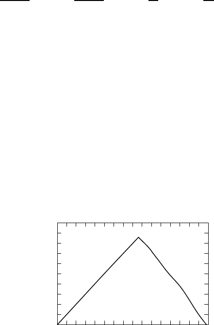
In Fig. W18.4 the allowed propagation band for the special case b D a/2 is illus-
trated. Let
k D
k
1
C k
2
2
,qD
k
2
k
1
2
,xD
ka
2
,yD
qa
2
.W18.32
Then the propagation-band conditions are
y
2
cos
2
y<x
2
cos
2
x, y
2
sin
2
y<x
2
sin
2
x. W18.33
Some wavelengths are able to propagate through the structure and others are blocked.
Typical materials for use in these devices, which may serve as either mirrors or
filters, are TiO
2
(n D 2.4) and SiO
2
(n D 1.46). Other combinations are MgF
2
(n D
1.38) and ZnS (n D 2.35) or MgF
2
with TiO
2
. A one-dimensional array of air holes
in a Si strip on top of an SiO
2
substrate has been fabricated
†
which displays a 400-nm
gap centered around $ D 1.54
µm.
To withstand bursts of light that may arise in pulsed lasers, one generally wants
matched coefficients of thermal expansion and high thermal conductivity. The reason
is that mismatched thermal expansion between successive layers will generate strains
upon heating that could produce dislocations at the interface. Repeated thermal expan-
sion may enlarge these dislocations and could eventually crack the material. The high
1.0
0.8
0.6
0.4
0.2
0
0 0.2 0.4 0.6 0.8 1.0 1.2 1.4 1.6
ka/2
qa/2
Allowed band
Figure W18.4. Region of parameter space for the propagation band.
†
J. S. Foresi et al, Nature, 390, 143(1997).

296 OPTICAL MATERIALS
thermal conductivity permits the material to cool rapidly. Optical damage is considered
further in Section W18.4.
The extension of the periodic structure to two or three dimensions has led to the
construction of what are called photonic crystals. By creating an array of holes in
a dielectric slab a photonic crystal operating in the microwaves has been built.
†
By
stacking Si rods in a face-centered tetragonal array with air filling the interstices, it
has been possible to fabricate
‡
a photonic crystal with a bandgap in the infrared (10 to
14.5
µm). Similarly, a periodic array of air-filled spheres in a titania crystal has been
fashioned to serve as a photonic crystal in the visible region of the spectrum.
§
Just as electrons may be localized in a medium with random scatterers, the same
is true of electromagnetic radiation. Localization in the microwave region has been
demonstrated by using a three-dimensional metal-wire network with random scatterers.
¶
It is clear that band-structure engineering is still at its early stage of development and
that new and exciting developments are rapidly emerging in the field.
W18.4 Damage
Laser damage to optical components, such as laser crystals, mirrors, polarizers, fibers,
electro-optic crystals, and prisms, is of concern in applications involving high power,
in both pulsed and continuous wave (CW) operation. Due to the optical absorption,
the materials heat up. Materials with a low heat capacity and low thermal conductivity
are more likely to reach high temperatures. In layered structures the mismatch in
thermal expansion coefficients can lead to crack formation and propagation. Typically,
bulk damage results for 10-ns pulses when the power density is in the range 200 to
4000 TW/m
2
.
One of the prime concerns is the phenomenon of self- focusing. This can occur in a
medium with a positive value of the nonlinear index of refraction, n
2
I. A laser beam
generally has a cross-sectional intensity profile with a higher intensity, IR,nearthe
axis than away from it. A typical form for the profile is Gaussian; that is,
IR D
2P
0
0f
2
e
2R/f
2
,W18.34
where R is the radial distance, P
0
the power in the beam, and f ameasureofthe
beam radius. The nonlinearity causes a larger value for the index of refraction, nR D
n
1
C n
2
IR, near the axis, when n
2
> 0. The medium behaves as a lens, and this tends
to focus the radiation [i.e., make fz decrease with increasing propagation distance,
z]. However, there is a competing effect due to diffraction, which tends to defocus the
radiation. This defocusing effect becomes stronger the smaller the value of f.There
exists a critical value of P
0
for which the focusing effect of the nonlinearity dominates
over the defocusing effect of diffraction and the beam focuses. When it does so, the
focal spot can become as small as a wavelength of light and the intensity can become
†
E. Yablonovitch et al, Phys. Rev. Lett., 67, 2295 (1991).
‡
S. Y. Lin et al, Nature, 394, 251 (1998).
§
J. Wijnhoven and W. Vos, Science, 281, 803 (1998).
¶
M. Stoychev and A. Z. Genack, Phys. Rev. B, 55, R8617 (1997).
OPTICAL MATERIALS 297
very large. A crude estimate of the critical power may be obtained by setting f D 1/k,
where k is the wave vector, and setting n
1
³ n
2
I.ThisgivesP
cr
¾ n
1
/n
2
k
2
.
Often, the electric field of the light can exceed the strength of the typical electric
fields in the solid and electrons can be accelerated to high energies, causing radiation
damage such as atomic displacements. The highly concentrated beam could cause local
melting, vaporization or ionization.
The situation is exacerbated when there are preexisting cracks or dislocations in the
material. When subjected to the (uniform) electric field of the laser, the local electric
field in the vicinity of the defect could be nonuniform, with particularly strong fields
being generated near sharp features. The same effects occur near a lightning rod, where
the strongest field occurs near the sharpest point. Local breakdown is likely to occur
near the defect, often inflicting additional damage there.
Defects are usually introduced into optical components during their fabrication stage.
For example, YAG is seen to have edge dislocations, helical dislocations, and zigzag
dislocations. Laser crystals are often plagued by secondary phases of crystals mixed in
with the primary phase. Bubbles are often present. These larger features can also serve
as scattering centers which deplete the laser beam of power and couple their signals to
other optical components. For this reason it is important that the optical components
be largely free of defects before being used in high-power applications.
REFERENCES
Polarized Light
Collett, E., Polarized Light: Fundamentals and Applications, Marcel Dekker, New York, 1993.
Shurcliff, W. A., Polarized Light, Harvard University Press, Cambridge, Mass., 1962.
PROBLEM
W18.1 The effective-mass tensor for an electron is diagonal in the xyz-coordinate
system and has elements m
Ł
1
, m
Ł
2
,andm
Ł
3
. A magnetic induction B is directed
in an arbitrary direction. If the cyclotron resonance frequency is eB/m
c
,find
an expression for m
c
.
CHAPTER W19
Surfaces
W19.1 Surface States
It is possible to introduce Tamm surface states by adding an attractive delta function
potential of strength U to the step potential introduced in Eq. (19.3):
†
Vz DV
0
z Uυz. W19.1
Note that the units of U are JÐm and that of V
0
are joules. The independent variables
in the Schr
¨
odinger equation can be separated with the substitution
r D z expik
jj
· r
jj
W19.2
where a solution can be found with
z D
expz if z>0,
expCqz if z<0.
W19.3
Here
D
k
2
jj
2mE
¯h
2
,W19.4a
where E<0and
q D
k
2
jj
2mE C V
0
¯h
2
.W19.4b
The function z is continuous at z D 0. The discontinuity in the derivative is deter-
mined by the strength of the delta function:
k
2
jj
2mE
¯h
2
C
k
2
jj
2mE C V
0
¯h
2
D
2mU
¯h
2
.W19.5
The solution to this equation gives the dispersion formula for the surface state band,
Ek
jj
. Note that at k
jj
D 0, E must lie below V
0
.
†
The material on this home page is supplemental to The Physics and Chemistry of Materials by Joel I
Gersten and Frederick W. Smith. Cross-references to material herein are prefixed by a “W”; cross-references
to material in the textbook appear without the “W”.
299
300 SURFACES
For the Shockley state one may develop a heuristic model to help understand its
origin. Consider a semiconductor and look at the states near the top of the valence band
at energy E
v
. For simplicity’s sake the effective mass of the holes will be assumed to
be isotropic and the band will be taken to be parabolic. The energy of an electron in
the valence band is then given by
Ek D E
v
¯hk
2
2m
Ł
h
.W19.6
One may develop a phenomenological Schr
¨
odinger equation based on a spatially depen-
dent mass mz with mz being the free-electron mass in vacuum and the negative of
the hole mass inside, that is,
mz D
m
Ł
h
if z<0
Cm if z>0.
W19.7
The resulting Schr
¨
odinger equation is
¯h
2
2
rÐ
1
mz
r
C E
v
z D E. W19.8
(The gradient operator is written in this split form so that the probability current
perpendicular to the surface may be proven to be continuous.)
As before, look for a solution of the form given by Eqs. (W19.2) and (W19.3). Now
q D
2m
Ł
h
¯h
2
E E
v
C k
2
jj
,W19.9a
D
k
2
jj
2mE
¯h
2
.W19.9b
The wavefunction z in Eq. (W19.3) is already continuous. The continuity of prob-
ability current perpendicular to the surface,
¯h
m
Ł
h
Im
Ł
d
dz
D
¯h
m
Im
Ł
d
dz
,W19.10
which is needed for a valid wavefunction, implies that
q
m
Ł
h
D
m
.W19.11
Thus the condition for the surface-state band is
1
m
Ł
h
2m
Ł
h
¯h
2
E E
v
C k
2
jj
D
1
m
k
2
jj
2mE
¯h
2
.W19.12

SURFACES 301
For k
jj
D 0 the surface state lies at an energy above the top of the valence band
(E>jE
v
j) but below the vacuum level (E<0):
Ek
jj
D 0 D
jE
v
j
1 C m
Ł
h
/m
.W19.13
More generally, one often employs a complex band structure in which the bulk
energy bands are extended to negative values of k
2
. This permits an effective Hamil-
tonian for the solid to be written which may be solved in conjunction with the
Hamiltonian for the electron in vacuum. The procedure of wavefunction matching
is similar to what was employed, but the implementation is more computational.
W19.2 Surfactants
Surface-active agents, or surfactants, are molecules that can radically alter the surface
or interface properties of a system even in small concentrations. The system usually
involves the liquid–solid, liquid–liquid, or liquid–gas interface. Sometimes the term
surfactant is used in reference to adsorbates [e.g., a monolayer of As is used on
Si (100) and Ge (100) to aid in Si–Ge heteroepitaxy]. Here, however, the focus is on
the liquid–solid interface. The surfactant molecule can consist of a long hydrocarbon
chain with an polar unit at one end. In the liquid the hydrocarbon chain must push
aside the liquid molecules to make room for the surfactant molecule. This involves
reducing the forces responsible for the liquid bonds. In water the surfactant molecule
must break apart the hydrogen bonds that exist. Since the hydrocarbon chain has
all its valence requirements satisfied by carbon–carbon or carbon–hydrogen bonds,
it is fairly inert to chemical or electrical interactions with the liquid. The net result
is that the liquid tends to expel the hydrocarbon in order to lower its energy. The
hydrocarbon chain is called hydrophobic, since it avoids being in water. On the other
hand, the polar end can lower its energy by immersing itself in the liquid. There
is an electrical attraction between the polar group and the liquid. This end is called
hydrophilic, due to its affinity for water. In order for the molecule to go into solution,
the energy decrease involved in the hydrophilic interaction must be greater than the
energy increase due to the hydrophobic interaction. Typical examples of surfactant
molecules are C
12
H
25
SO
4
Na
C
and C
12
H
23
COO
Na
C
.
The surface or interface provides a region of space where both the hydrophobic and
hydrophilic tendencies can be satisfied simultaneously. If the polar group lies in the
liquid and the hydrocarbon chemisorbs onto the surface, a doubly low energy can be
achieved. The lowest-energy state of the system therefore involves an accumulation of
the surfactant molecules at the surface. This means that even in small concentrations
the molecules will aggregate at the surface.
The adsorption of the surfactants at the surface or interface lowers the interfacial
tension, often significantly. This can radically alter such properties as surface diffusion,
chemisorption, and crystal growth. Since the surface atoms are now binding themselves
to the surfactant molecules, they have fewer bonding electrons to form the surface
bonds, thereby depressing the surface tension.
The surface tension drops monotonically with increasing surfactant concentration
until a critical concentration is reached (usually when the surface is completely
covered). Beyond that the surface properties no longer change. This curious behavior
is traced to an interaction that the surfactant molecules have among themselves. The

302 SURFACES
surfactant molecules can form a composite unit in solution called a micelle. The micelle
comes about, for example, by creating a ball of molecules with their hydrocarbon chains
directed toward the center of the sphere and the polar groups directed outward into the
liquid. Liquid is not present in the interior of the micelle. This also satisfies both the
hydrophobic and hydrophilic tendencies of the molecule. Other geometries, involving
micellar rods or parallel sheets, are also possible.
To understand why a surfactant molecule would prefer to leave the liquid and adsorb
onto a surface, one must compare the energies of the molecule in solution with it being
adsorbed on the surface. A crude model for the interaction of the surfactant molecule
with the liquid may be obtained by imagining that the polar end is a point dipole that
carves out a small spherical cavity around it in the liquid. Let the sphere have a radius
equal to a. Denote the strength of the dipole by , and the electric permittivity of the
liquid by . The electrostatic potential in all of space is then given by
r, D
E
0
r cos C
cos
4
0
r
2
if r<a,
p cos
4r
2
if r>a,
W19.14
where, in order to satisfy the continuity of and the radial component of the electric
displacement vector D
r
p D
3
0
C 2
,W19.15
E
0
D
2
4
0
a
3
0
0
C 2
.W19.16
Here E
0
is the electric field in the cavity due to the polarization charges in the liquid.
The interaction energy of the dipole with this field, U
s
, is called the solvation energy:
U
s
D
2
4
0
a
3
0
0
C 2
.W19.17
The hydrophobic interaction, U
i
, may be estimated by imagining that the hydrocarbon
chain carves out a cylindrical cavity with surface area A. This causes a rise in the
surface energy given approximately by the product of the surface tension of the liquid
and the area
U
i
D #A. W19.18
For the molecule to go into solution, the total energy, U
s
C U
i
, must be negative.
When chemisorption of the surfactant molecule occurs, there is an additional energy
U
c
, corresponding to the chemisorption bond. Since U
c
< 0 it is favorable for the
surfactant molecules to go out of solution and adsorb onto the surface.
W19.3 Adsorption
Suppose that a solid is exposed to a monatomic gas at temperature T and pressure P.
Atoms will strike the surface and a fraction, s, will stick to it. It is therefore important