Gersten J.I., Smith F.W. The Physics and Chemistry of Materials
Подождите немного. Документ загружается.


262 MAGNETIC MATERIALS
obtained. Since in these metallic ferromagnets the alternating field H
wave
penetrates
the material only to within the skin depth υ at the surface, defined in Eq. (W17.16),
surface preparation is very important.
Additional parameters that can be obtained from measurements of ω
r
in ferromag-
nets and ferrimagnets are the magnitudes of the effective anisotropy field H
K
and the
effective molecular field H
eff
. For example, the resonant frequency due to magnetic
anisotropy effects alone is obtained when H D 0andH
tot
D H
a
in Eq. (W17.18).
With H
K
D 2K/
0
M
s
, measurement of ω
r
D g
0
H
K
can yield K if M
s
is known
from independent measurements.
In antiferromagnets it is possible for the magnetizations of the two spin sublattices to
precess at the same frequency. For a uniaxial antiferromagnet in zero applied magnetic
field, the resonant frequency is
ω
r
D 3
0
H
K
H
K
C 2H
eff
, W17.19
where H
K
is the effective anisotropy field and H
eff
is the effective molecular field.
Va l ue s o f H
K
and H
eff
obtained for the antiferromagnet MnF
2
via antiferromagnetic
resonance are 700 and 43,000 kA/m, respectively.
For ferrimagnets the resonance occurs in essentially the same way as in ferromag-
nets as long as H
eff
× H or H
K
. The resonant frequency can lie in the range from
microwave to infrared frequencies, depending on the particular mode excited.
Magnetic Relaxation. The time-dependent changes in the magnetization M which
lag behind changes in an applied magnetic field H are known either as magnetic relax-
ation or as the magnetic aftereffect. Eddy currents can also lead to relaxation effects
and have already been discussed. These magnetic relaxation effects can be reversible
as long as no irreversible changes in the magnetic microstructure have occurred due
to diffusion or to macroscopic structural changes.
Following a discontinuous change in H, changes in M can exhibit exponential time
dependencies expressed either by
Mt D M
0
1 e
t/7
W17.20a
or by
Mt D M
0
e
t/7
,W17.20b
where 7 is the time constant for the relaxation process. The mathematical formalism
for the description of magnetic relaxation is similar to that employed in Chapter W10
for a description of the anelastic mechanical properties of materials. The energy losses
associated with periodic magnetic-relaxation processes typically occur at frequencies
ω D 2%/7, which are lower than those associated with ferromagnetic resonance. The
characteristic time 7 for magnetic relaxation depends on the nature of the microscopic
processes controlling the relaxation process. The lifetime 7 can be temperature depen-
dent if the process is thermally activated. Examples of such processes include diffusion
of atoms or the hopping of electrons from atom to atom.
A physical mechanism for the magnetic relaxation observed in BCC ˛-Fe was
first proposed by Snoek.
†
The Snoek effect is also discussed in Chapter 10, where
†
J. Snoek, Physica, VI, 591 (1939).
MAGNETIC MATERIALS 263
its influence on the elastic properties of ˛-Fe is described. Relaxation of the elastic
properties is proposed to be due to the redistribution of C or N atoms among the
available interstitial sites in the BCC crystal structure. The same redistribution of C or
N affects the magnetization of the material through the magnetoelastic interaction and
so is related to the magnetostriction of ˛-Fe. An alternative explanation for the origin
of the observed magnetic relaxation as suggested by N
´
eel involves the effect on the
anisotropic exchange interaction between Fe atoms due to the intervening interstitial
CorNatoms.
Relaxation of the magnetization can also result from the thermally activated rota-
tions of the magnetic moments of magnetic domains, of magnetic particles, or even
of individual spins over energy barriers, which can be due, for example, to the effects
of magnetic anisotropy. In small magnetic particles this effect is closely related to
superparamagnetism. In the amorphous magnetic materials known as spin glasses,
relaxation of the remanent magnetization occurs via the activation of single spins or
clusters of strongly interacting spins over local energy barriers so that their magnetic
moments point in energetically favorable directions. There is often a broad distribu-
tion of time constants associated with these processes so that the “freezing” process
does not follow a simple thermal-activation law with a single time constant or acti-
vation energy. This process of spin glass “freezing” occurs over a wide range of
temperatures.
The term magnetic viscosity is often used to describe the magnetic relaxation of
collections of small magnetic particles or of spin glasses, for which there can exist a
wide distribution of relaxation times resulting from a corresponding broad distribution
of energy barriers to magnetization rotation, domain wall motion, and so on. In this
case, the time dependence of the magnetization is often approximated by
Mt D M
0
S lnt/7
0
, W17.21
where M
0
and 7
0
are constants and S DdM/dln t is the magnetic viscosity. There
are good reasons, however, to avoid the use of this simple logarithmic time dependence
for Mt because such an expression does not in general fit experimental observations at
times that are either short or long compared to the time duration t
exp
of the measurement
(Aharoni, 1996, pp. 100–105). Relaxation processes for which 7 − t
exp
or 7 × t
exp
will clearly fall outside the range of validity of Eq. (W17.21).
In many materials the magnetic viscosity levels off to a constant value at low
temperatures, a result that is contrary to what is expected from thermally activated
processes. This effect has been attributed to the quantum-mechanical reversal of the
magnetization (i.e., to quantum tunneling of the magnetization).
Magnetomechanical Damping. The energy losses associated with mechanical
vibrations in magnetic materials, referred to as magnetomechanical damping,are
generally larger than those observed in nonmagnetic materials. The stresses causing
the vibrations in a magnetic material lead to strains, which in turn cause changes in
the magnetization via magnetostriction. The result is that by Faraday’s law, oscillatory
stresses can result in the generation of eddy currents with their associated losses in
a magnetic material. Losses due to domain wall motion can also result from applied
stresses.

264 MAGNETIC MATERIALS
TABLE W17.2 Technologically Important Magnetic Materials
Magnetically
Material Hard or Soft Applications
Metals
Steels (alloyed with W, Cr, etc.) Hard Permanent magnets
Fe particles (oxide-coated) Hard Magnetic recording media
Fe
x
Ni
1x
alloys:
78 Permalloy, Fe
0.22
Ni
0.78
;
Supermalloy,
Fe
0.16
Ni
0.79
Mo
0.05
;
Invar, Fe
0.65
Ni
0.35
Soft Electromagnetic devices,
magnetic recording heads,
precision instruments
Mumetal: ³ Fe
0.18
Ni
0.77
Cu
0.05
Soft Magnetic shielding,
transformer cores
Co alloys (CoCr, etc.) Hard Magnetic recording media
Fe
1x
Si
x
Soft Transformer cores
Fe:Si:Al alloys: Sendust,
a
85Fe10Si5Al
Soft Magnetic recording heads
Alnico alloys: Alnico 5,
a
51Fe14Ni8Al24Co3Cu
Hard Permanent magnets
Amorphous rare
earth–transition
metal alloys
Soft Magneto-optical recording
media
Amorphous Fe:B:Si:C alloys Soft Magnetostrictive elements
Intermetallic compounds
SmCo
5
and Sm
2
Co
17
Hard Permanent magnets
Nd
2
Fe
14
B Hard Permanent magnets
TbFe
2
and (Tb
0.3
Dy
0.7
)Fe
2
(Terfenol-D)
Soft Magnetostrictive elements
Ceramic compounds
3-Fe
2
O
3
Hard Magnetic recording media
CrO
2
Hard Magnetic recording media
Mn
1x
Zn
x
Fe
2
O
4
Soft Magnetic recording heads
Y
3
Fe
5
O
12
(YIG) Soft Microwave technology
BaOÐ6Fe
2
O
3
or SrOÐ6Fe
2
O
3
(BaFe
12
O
19
,SrFe
12
O
19
)
Hard Permanent magnets,
magnetic recording media
a
Composition given in weight percent.
W17.7 Technologically Important Magnetic Materials
See Table W17.2 for magnetic materials described in Chapters 17 and W17.
W17.8 Details on Permanent-Magnet Materials
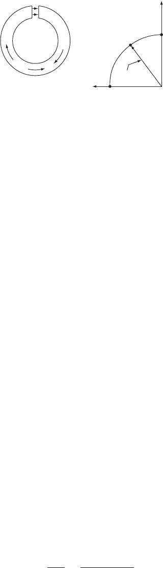
To illustrate the operation of a permanent magnet, consider a toroidal magnet producing
a magnetic field H
g
in an airgap, as shown schematically in Fig. W17.6a. The intro-
duction of the air gap leads to the presence of a demagnetizing field H
D
DNM inside
the magnet, directed opposite to both M and B. When no external field H is applied
to the magnet, its operating point will lie somewhere on the portion of the B –H or
M–H loop in the second quadrant.
The portion of the B–H loop in the second quadrant which determines the operation
of a permanent magnet is the demagnetization curve, shown in Fig. W17.6b. Note that
MAGNETIC MATERIALS 265
Load line
MB
0
B
r
B
H'
c
H
i
B
g
= µ
o
H
g
H
D
= −NM
H
g
(a) (b)
Figure W17.6. Permanent magnet: (a) configuration of a toroidal permanent magnet supplying
a magnetic field H
g
to an air gap; (b) portion of the B–H loop that determines operation of the
permanent magnet, which is the demagnetization curve in the second quadrant.
it is standard practice to plot B–H curves for permanent-magnet materials rather than
the usual M–H magnetization curves. Here the magnetic induction B D
0
H
i
C M in
the material is shown plotted versus the internal magnetic field H
i
. The demagnetization
curve extends from the remanent induction B
r
D
0
M
r
at H
i
D 0 down to H
i
DH
0
c
,
the coercive field corresponding to B D 0. Note that B
r
is the maximum flux density
that the magnet can produce under closed-circuit conditions (i.e., in the absence of an
air gap). The operating point for the magnet in the absence of an external magnetic
field is determined by the presence of the air gap and the resulting demagnetizing field
H
D
. In this case the internal magnetic field is given by
H
i
D H
D
DNM.W17.22
The operating point is thus not at B
r
but rather, at the point where the magnetic
induction B< B
r
is given by
B D
0
H
D
C M D
0
1 NM.W17.23
Here 1 ½ N ½ 0 is the demagnetizing factor for the magnet with the air gap. The
magnetization M is less than M
r
, due to the presence of H
D
. Note that in the air gap
B
g
D
0
H
g
³ B if the gap is narrow enough so that the fringing magnetic fields are small.
For a given amount or volume of magnetic material, the highest field H
g
in a given
air gap is achieved when the energy density product BH of the magnetic induction
B and the field H
i
inside the magnet is maximized. The energy density product is
also known as the strength of the magnet. The operating point of the magnet should
therefore lie as close as possible to the point on the B –H curve for which BH is
largest [i.e., at BH
max
]. The actual energy stored per unit volume is BH/2. In this
way the permanent magnet needed to produce a given magnetic field can be as small
as possible.
The actual point of operation of the permanent magnet is determined by the demag-
netizing factor N of the magnet with the air gap and corresponds to the magnetic
induction given in Eq. (W17.23). The slope of the line connecting the origin to the
operating point on the B –H curve is therefore
s D
B
H
int
D
0
1 N
N
.W17.24

266 MAGNETIC MATERIALS
This is the load line of the magnet as shown in Fig. W17.6. Slopes of s D1and s D 0
correspond, respectively, to the limiting values of N D 0andN D 1. For N − 1, the
slope is given approximately by s D
0
/N.
Transition Metal Alloys. The ferromagnetic 3d transition metals Fe, Co, and Ni
are present in essentially all of the widely used permanent-magnet materials listed
in Table W17.3, either in alloys with each other or with other transition metals,
in intermetallic compounds with rare earth metals, or in ceramic compounds. The
magnetic anisotropy field H
K
for pure Fe is only ³ 40 kA/m, which eliminates pure
Fe as a material for most permanent-magnet applications due to its relatively low coer-
cive field H
c
. The precipitation-hardened alloys based primarily on Fe, Ni, Al, and Co,
as well as some steels that have permanent-magnet applications, are discussed next.
Precipitation-Hardened Alloys. Precipitation hardening in the case of magnetic mate-
rials refers to the use of heat treatments to enhance the magnetic hardness of the material
by the precipitation of a second phase which can pin domain walls and hence increase
H
c
. By varying both the specific processing treatments employed and the composition,
the alloys known in the United States as Alnico and based on Fe, Al, Ni, Co, and so
on, can be prepared with magnetic properties, which have led to their widespread use
in permanent magnets. Many other transition metal alloys based on Fe, Co, or Ni can
also undergo precipitation hardening for use in permanent magnets.
TABLE W17.3 Properties of Permanent-Magnet Materials
BH
max
B
r
H
0
c
b
T
C
Material kJ/m
3
a
(T) (kA/m) (K)
Transition Metal Alloys
Alnico 5
c
: (51Fe, 14Ni, 8Al,
24Co, 3Cu)
35.8 1.25 43.8 1120
Steels
c
Cobalt steel (35Co, 0.7C, 7.7 0.95 19.1
4Cr, 5W, bal. Fe)
Tungsten steel (5W,
0.3Mn, 0.7C, bal. Fe)
2.5 1.03 5.6
Rare Earth–Transition Metal Intermetallic Compounds
Nd–Fe–B
d
200–380 1.0–1.4 700–1000 580
SmCo
5
e
130–180 0.8–0.9 600– 670 990
Sm(Co,Fe,Cu,Zr)
7
e
200–240 0.95–1.15 600–900 1070
Ceramics
BaOÐ6Fe
2
O
3
d
28 0.4 250 720
a
Note that 1 kJ/m
3
D 1kAÐT/m.
b
The quantity H
0
c
is the coercive field corresponding to B D 0.
c
Data from D. R. Lide and H. P. R. Frederikse, eds., CRC Handbook of Chemistry and Physics, CRC Press,
Boca Raton, Fla., 1994, pp. 12–113. The alloy composition is given in weight percent. See the Handbook
for methods of fabrication.
d
Commercial material from Magnet Sales & Manufacturing Catalog.
e
DatafromK.H.J.Buschow,Rep. Prog. Phys., 54, 1123 (1991). Sm(Co,Fe,Cu,Zr)
7
is a two-phase material
which can be thought of as a composite of SmCo
5
-andSm
2
Co
17
-type phases.
MAGNETIC MATERIALS 267
16
12
8
4
0
(c)
(b)
(a)
800 600 400 200 0
H
(Oe)
B
(kG)
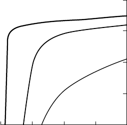
Figure W17.7. Demagnetization curves of an Alnico alloy, 51.8Fe, 7.5Al, 23Co, 3Cu, 0.7Nb
in wt %, cooled from T D 1250
°
C and annealed at T D 560 to 590
°
C: (a) randomly oriented
grains with no heat treatment in a magnetic field; BH
max
D 14 kJ/m
3
;(b) randomly oriented
grains heat-treated in a magnetic field; BH
max
D 43 kJ/m
3
;(c) columnar grains heat-treated
in a magnetic field; BH
max
D 69 kJ/m
3
. [From J. E. Gould, Proc. I.E.E., 106A, 493 (1959).
Copyright 1959, IEE Publishing.]
A typical precipitation-hardened alloy is Alnico 5, which has the composition (in
weight percent) 51Fe, 14Ni, 8Al, 24Co, and 3Cu. The extrinsic magnetic properties
of Alnico 5 are listed in Table W17.3. Due to their high T
C
values of ³ 1120 K,
Alnico 5 and similar alloys have higher maximum operating temperatures than most
other permanent magnets. Following quenching from T ³ 1200
°
C and annealing in
the range 500 to 600
°
C, these alloys consist of highly magnetic rodlike particles of
˛-Fe embedded in a weakly magnetic matrix of Ni and Al. When cooled slowly from
T D 1200
°
CtobelowT
C
in a magnetic field, the precipitation occurs in such a way
that the long axes of the particles become aligned with each other, thus increasing the
shape magnetic anisotropy of the material and its coercive field. This is illustrated in
Fig. W17.7, where the demagnetization curves for an Alnico alloy are shown following
three different types of thermomagnetic treatment.
Alnico alloys have high values of B
r
, due to their high Fe contents but have
lower coercive fields H
c
compared to the other permanent-magnet materials listed in
Table W17.3. The magnitude of the coercive fields of Alnico alloys can be attributed
to the pronounced shape anisotropy of the magnetic particles. The maximum magnetic
anisotropy attainable in these alloys is determined by the difference (N
?
N
jj
)ofthe
demagnetization coefficients of the particles [see Eq. (17.16)]. Even better magnetic
properties [i.e., higher B
r
, BH
max
,andH
0
c
] can be found in highly [100]-oriented
alloys with columnar microstructure obtained by controlled solidification from the melt.
Co is apparently required for the appearance of significant magnetic anisotropy in
these alloys, while additions of Nb and Ti can also lead to increased values of H
0
c
.The
physical reasons for these changes are not clear.
Steels. Steels alloyed with W, Cr, and Co have been used extensively as permanent
magnets. Given the proper heat treatment, these alloying elements can react with the
C in the steel, forming precipitates of carbides of W, Cr, and Co which act to impede
the motion of domain walls. Anisotropy effects associated with the shapes of these
carbide precipitates are apparently not as strong as in typical Alnico alloys, which
268 MAGNETIC MATERIALS
have coercive fields that are higher by a factor of 3 or more. The low values of H
c
in
steels limit their attainable values of BH
max
.
The martensitic lattice transformations from the FCC 3-phase to the BCC ˛-phase
that occur in these steels upon cooling lead to lattice distortions due to the resulting
high internal stresses. The magnetic anisotropy of magnet steels is therefore enhanced
by stress-related magnetostrictive effects.
Rare Earth–Transition Metal Intermetallic Compounds. The most attractive
materials for current high-performance permanent magnets are the intermetallic
compounds based on rare earths and the ferromagnetic transition metals Fe and Co.
These materials, sometimes referred to as supermagnets, possess the highest-known
coercive fields, H
c
³ 1100 kA/m, and energy products, BH
max
³ 300 kJ/m
3
.The
low-symmetry hexagonal or tetragonal crystal structures of these materials expose
the rare earth ions to the high magnetocrystalline anisotropy needed for enhancing
the coercive field. The transition metal components keep T
C
sufficiently high for
practical applications. An important advantage of the rare earth–based permanent-
magnet materials is that they can be used to generate the same magnetic fields as
iron-core electromagnets, which are 10 times as massive. This feature has made possible
miniaturized electrical motors and, in general, smaller and lighter electromagnetic
devices and products. Larger magnetic inductions, in the range 3 to 10 T, require
the use of superconducting magnets. The important intermetallic compounds SmCo
5
,
Sm
2
Co
17
,andNd
2
Fe
14
B are discussed next.
SmCo
5
and Sm
2
Co
17
. The first permanent-magnet materials, consisting of rare
earth–transition metal (RE–TM) intermetallic compounds and based on Sm and Co,
were discovered in the early 1960s. These materials have high values of M
sat
, due to
the ferromagnetic coupling of the Sm and Co spins. This is not found to be the case
in alloys containing heavy rare earths, such as Gd, where the RE–TM coupling is
antiferromagnetic. The substitution of other magnetic 3d transition metals, such as Fe,
Mn, Cr, or Ni for Co, in these RE–TM compounds has not been successful, due to
the resulting low T
C
values or low magnetic anisotropies. The high T
C
values of these
alloys make them attractive for use in applications in which the operating temperature
of the magnet is relatively high.
According to the Hume–Rothery rules described in Chapter 12, the fact that the RE
ionic radii are much greater than those of the TM ions strongly limits the possibility of
the formation of RE–TM solid solutions. Instead, a series of intermetallic compounds
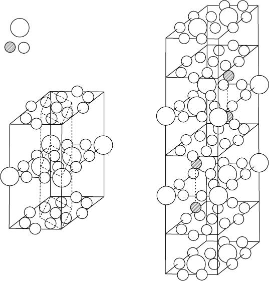
are formed. The crystal structure of SmCo
5
is hexagonal and that of Sm
2
Co
17
is
trigonal (rhombohedral) (Fig. W17.8). In the SmCo
5
structure the planes containing
the Sm ions and twice as many Co ions lie between adjacent planes containing only
Co atoms. The Sm
2
Co
17
structure is derived from the SmCo
5
structurebyanordered
replacement of one-third of the Sm ions by pairs (“dumbbells”) of Co ions that are
aligned along the c axis.
The overall magnetocrystalline anisotropies of both Sm–Co compounds is uniaxial,
with SmCo
5
having the largest value observed for any magnetic material, corresponding
to an effective magnetic anisotropy field H
K
³ 3.2 ð10
4
kA/m. In the Sm
2
Co
17
struc-
ture the dumbbell pairs of Co atoms prefer to have their magnetic moments lying in
the basal plane, thereby reducing the overall magnetic anisotropy of the material.
Recently, Fe-based compounds such as Sm
2
Fe
17
N
3x
have been developed with high
T
C
values, up to 749 K, strong uniaxial anisotropy, and high saturation magnetization.
MAGNETIC MATERIALS 269
R ATOM
Co OR TM ATOM
Z=1
Z = 1
Z=1/2
Z=0
Z = 5/6
Z = 2/3
Z = 1/2
Z = 1/3
Z = 1/6
Z = 0
RCo
5
STRUCTURE
(CaCu
5
TYPE)
RHOMBOHEDRAL MODIFICATION
[Th
2
Zn
17
TYPE]
+
+
+
+
+
+
+
+
Figure W17.8. Crystal structures of the intermetallic compounds hexagonal SmCo
5
and rhom-
bohedral Sm
2
Co
17
. The substituted “dumbbell” Co ions in Sm
2
Co
17
appear crosshatched. (From
K. Kumar, J. Appl. Phys., 63, R13 (1988). Copyright 1988 by the American Institute of Physics.)
The N atoms enter octahedral interstitial sites in the structure. In materials such as
Sm
2
Fe
15
Ga
2
C
3x
, C atoms can serve the same purpose. In addition, Ga has been
substituted for some of the Fe in order to increase T
C
and the uniaxial anisotropy field.
The presence of the interstitial N or C atoms expands the structure and apparently has
the effect of strengthening the magnetism by supporting the formation of ferromagnetic
networks of Fe atoms in these materials.
The best commercially available materials are precipitation-hardened composites
consisting of a Sm
2
Co
17
-type phase embedded in a SmCo
5
-type matrix. These materials
combine the high M
sat
value of Sm
2
Co
17
with the high magnetic hardness of SmCo
5
.
The high observed values of H
c
result from the alignment of the easy axes of the
particles parallel to each other in the material. These composites have the approximate
composition SmCo
7.7
and also typically contain some Fe, Cu, and Zr atoms replacing
some of the Co.
Powder metallurgy techniques are used in the fabrication of these magnets. The
elements are first melted together, then ground into micrometer-sized particles. The c
axes of the particles are aligned magnetically in a magnetic field. The particles are then
densified by sintering. Finally, thermal treatments are utilized for the optimization of H
c
.
270 MAGNETIC MATERIALS
Nd
2
Fe
14
B. The intermetallic compound Nd
2
Fe
14
B, discovered in 1984, exhibits the
most desirable magnetic properties of all permanent-magnet materials at room temper-
ature (see Table W17.3). Since it is based on Fe, Nd
2
Fe
14
B has the advantage of being
less expensive than the Co-based materials discussed earlier. In addition, Nd
3C
has
a larger magnetic moment than Sm
3C
and couples ferromagnetically to the magnetic
moments of the Fe atoms, leading to a higher magnetization. The magnetic coupling
between the Nd 4f electrons and the Fe 3d electrons is believed to be indirect, occur-
ring not via the RKKY interaction through the conduction electrons but instead, through
the rare earth 5d electrons. The ion Nd
3C
has an outer electron configuration 4f
3
and
contributes one 5d and two 6s electrons to the conduction bands. The Fe magnetic
moment is ³ 2.1
B
, close to the value found in pure ˛-Fe.
Nd
2
Fe
14
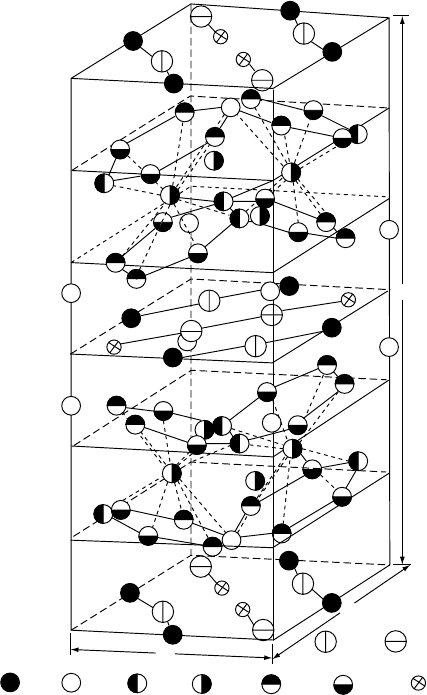
B has a complicated tetragonal unit cell with dimensions a D 0.88 nm and
c D 1.22 nm and containing 68 atoms (i.e., four formula units). The crystal structure
presented in Fig. W17.9 is essentially a layered one, with sheets of Nd and B atoms
c
a
a
Fe c B g
Nd f Nd g
Fe e Fe j
1
Fe j
2
Fe k
1
Fe k
2
Figure W17.9. Tetragonal unit cell of Nd
2
Fe
14
B. The structure is essentially a layered one, with
sheets of Nd and B atoms (and some Fe atoms) lying between close-packed double layers of Fe
atoms. (From J. F. Herbst, Rev. Mod. Phys., 63, 819 (1991). Copyright 1991 by the American
Physical Society.)
MAGNETIC MATERIALS 271
(and some Fe atoms) lying between close-packed double layers of Fe atoms. Six
crystallographically distinct positions for the Fe atoms and two for the Nd atoms exist
in this structure. The origin of the strong uniaxial magnetocrystalline anisotropy of
Nd
2
Fe
14
B is the low symmetry of the Nd sites and, apparently, the interaction of the
Nd
3C
ions with the resulting strong crystal fields.
Despite the crystal-field effects, the Nd
3C
ions retain their full magnetic moment
due to the strong on-site spin–orbit interaction (i.e., the orbital angular momentum L
is not quenched). In this structure the Nd atoms lie within hexagonal prisms of Fe
atoms while the B atoms lie within trigonal prisms of Fe atoms. These trigonal prisms
are also a common and fundamental feature of transition metal–metalloid structures
such as those found in the FeB and Fe
3
C systems. The role of the B in Nd
2
Fe
14
Bis
to produce a low-symmetry crystal structure without causing an appreciable reduction
of the magnetization of the material.
The material Nd
2
Fe
14
B is a uniaxial ferromagnet with a fairly low T
C
value of
585 K and with the all Nd and Fe spins aligned at room temperature parallel to the c
axis, the easy axis for the magnetization M. The resulting saturation magnetization is
quite high, M
sat
D 1270 kA/m, even higher than the value 800 kA/m for SmCo
5
.As
a measure of the strength of the uniaxial magnetic anisotropy, the effective magnetic
anisotropy field H
K
is about 7200 kA/m.
NdFeB magnet material can be formed by rapid solidification, (i.e., by melt spinning
and quenching into ribbon form) or by the pressing and sintering of powder mate-
rial. The ribbon material has a metastable microstructure that is very sensitive to
the quenching rate. The optimum material consists of 20-nm grains of Nd
2
Fe
14
B
surrounded by an approximately 2-nm-thick amorphous intergranular phase. The grain
boundaries pin the domain walls, thereby impeding their motion and increasing the
coercive field. Processing is necessary to transform the brittle ribbon material into the
final dense form, with the two-phase microstructure suitable for permanent-magnet
applications.
Improvements in the properties of Nd
2
Fe
14
B can be achieved by introducing a
variety of alloying elements (e.g., substituting Co for some of the Fe atoms raises T
C
,
replacing some of the Nd by Dy or Gd atoms enhances the anisotropy, etc.). Currently
used NdFeB magnet materials are based on Nd
2
Fe
14
B but actually correspond to a
range of compositions and microstructures.
Ceramics. Permanent magnets based on the ceramic compounds barium ferrite,
BaOÐ6Fe
2
O
3
(BaFe
12
O
19
), strontium ferrite, SrOÐ6Fe
2
O
3
, and their solid solutions
have the advantages of very high coercive fields, H
c
³ 200 kA/m, due to the strong
uniaxial magnetocrystalline anisotropy field of this material, H
K
³ 1300 kA/m. They
also possess high environmental stability, due to the absence of problems associated
with oxidation. The magnetic properties depend critically on the sintering of the ceramic
powders to obtain bulk material. The fact that H
c
is typically well below H
K
may be
due to the platelet shape of the particles and the fact that the resulting shape anisotropy
opposes the larger uniaxial magnetocrystalline anisotropy. This issue is also mentioned
in Section W17.9, where the use of barium ferrite in magnetic recording media is
discussed.
These ceramic materials are ferrimagnetic and thus have relatively low values of B
r
and M
sat
. Their high values of H
c
and low cost have nevertheless led to widespread
applications in permanent magnets and in magnetic recording media. Their high