Fung R.-F. (ed.) Visual Servoing
Подождите немного. Документ загружается.

Visual Servoing for UAVs
191
obtained with these systems. These characteristics can help solving common vision
problems such as occlusions, and can offer more tools for control, tracking, representation of
objects, object analysis, panoramic photography, surveillance, navigation of mobile vehicles,
among other tasks. However, in spite of the advantages offered by these systems, there are
some applications where the hardware and the computational requirements make a multi-
camera solution inadequate, taking into account that the larger the number of cameras used,
the greater the complexity of the system is.
For example, in the case of pose estimation algorithms, when there is more than one camera
involved, there are different subsystems that must be added to the algorithm:
• Camera calibration
• Feature Extraction and tracking in multiple images
• Feature Matching
• 3D reconstruction (triangulation)
Nonetheless, obtaining an adequate solution for each subsystem, it could be possible to
obtain a multiple view-based 3D position estimation at real-time frame rates.
This section presents the use of a multi-camera system to detect, track, and estimate the
position and orientation of a UAV by extracting some onboard landmarks, using the
triangulation principle to recovered their 3D location, and then using this 3D information to
estimate the position and orientation of the UAV with respect to a World Coordinate System.
This information will be use later into a UAV’s control loop to develop positioning and
landing tasks.
3.0.2 Coordinate systems
Different coordinate systems are used to map the extracted visual information from ℜ
2
to ℜ
3
,
and then to convert this information into commands to the helicopter. This section provides
a description of the coordinate systems and their corresponding transformations to achieve
vision-based tasks.
There are different coordinate systems involved: the Image Coordinate System (X
i
), that
includes the Lateral (X
f
) and Central Coordinate Systems (X
u
) in the image plane, the Camera
Coordinate System (X
c
), the Helicopter Coordinate System (X
h
), and an additional one: the World
Coordinate System (X
w
), used as the principal reference system to control the vehicle (see
figure 3).
• Image and Camera Coordinate Systems
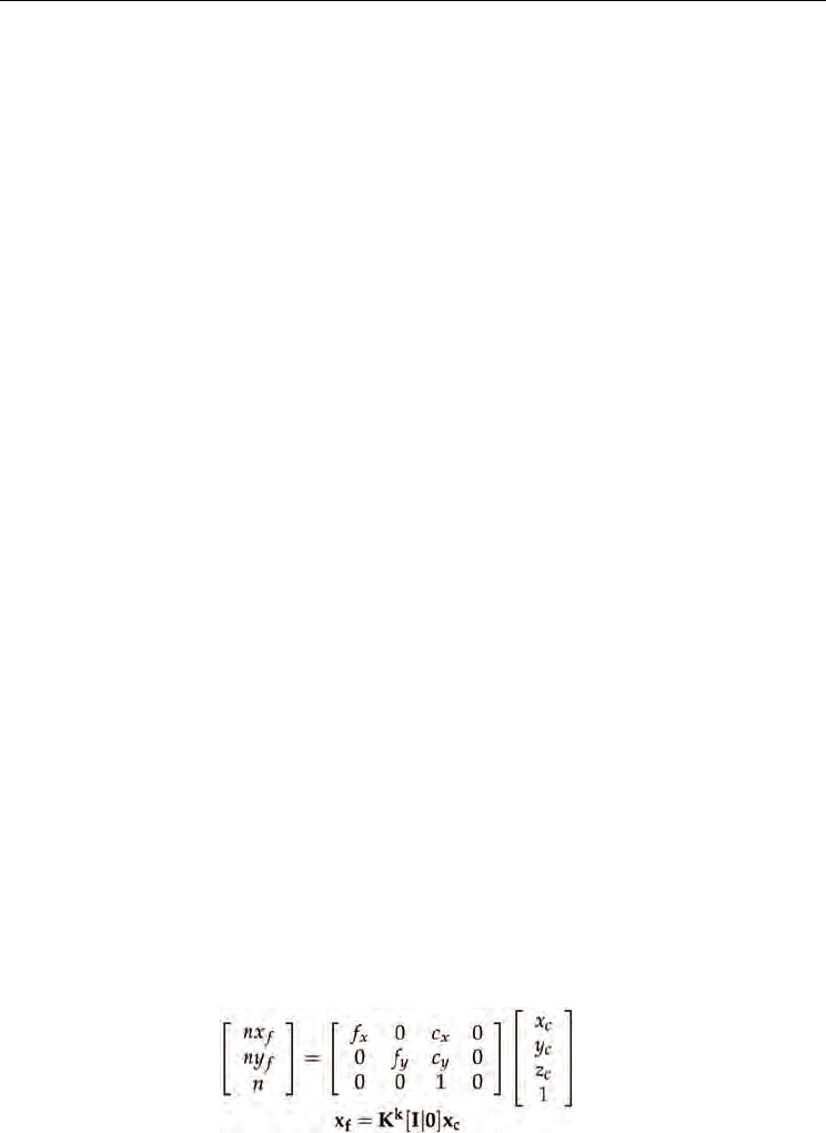
The relation between the Camera Coordinate System and the Image Coordinate System is taken
from the “pinhole” camera model. It states that any point referenced in the Camera Coordinate
System x
c
is projected onto the image plane in the point x
f
by intersecting the ray that links
the 3D point x
c
with the center of projection and the image plane. This mapping is described
in equation15, where x
c
and x
f
are represented in homogenous coordinates.
(15)
The matrix K
k
contains the intrinsic camera parameters of the k
th
camera, such as the
coordinates of the center of projection (c
x
, c
y
) in pixel units, and the focal length (f
x
, f
y
), where
Visual Servoing
192
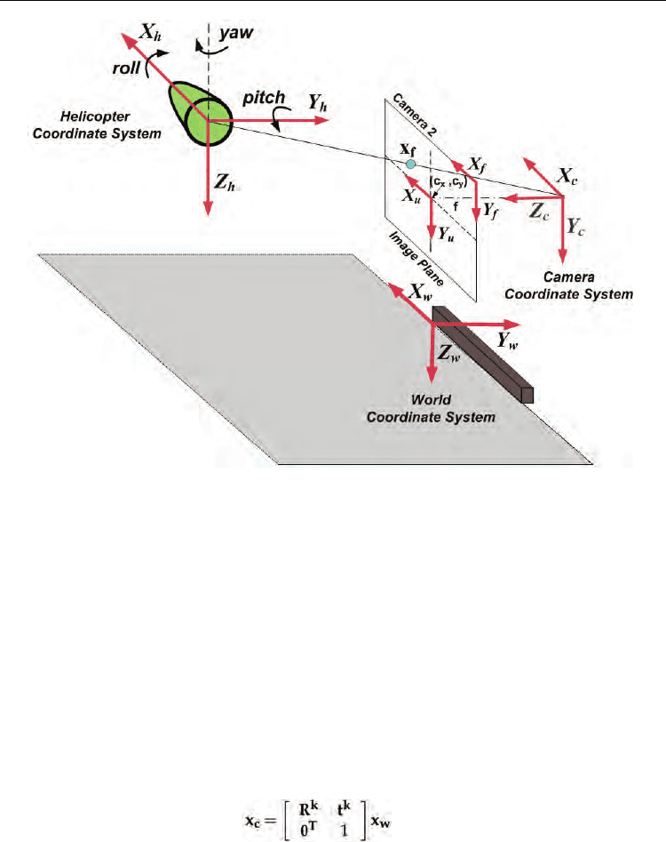
Fig. 3. Coordinate systems involved in the pose estimation algorithm.
f
x
= fm
x
and f
y
= fm
y
represent the focal length in terms of pixel dimensions, being m
x
and m
y
the number of pixels per unit distance.
The above-mentioned camera model assumes that the world point, the image point, and the
optical center are collinear; however, in a real camera lens there are some effects (lens
distortions) that have to be compensated in order to have a complete model. This
compensation can be achieved by the calculation of the distortion coefficients through a
calibration process (Zhang (2000)), in which the intrinsic camera parameters, as well as the
radial and tangential distortion coefficients, are calculated.
• Camera and World Coordinate Systems
Considering that the cameras are fixed, these systems are related by a rigid transformation
that allows to define the pose of the k
th
camera in a World Coordinate Frame. As presented in
equation (16), this transformation is defined by a rotation matrix R
k
and a translation vector
t
k
that link the two coordinate systems and represent the extrinsic camera parameters. Such
parameters are calculated through a calibration process of the trinocular system.
(16)
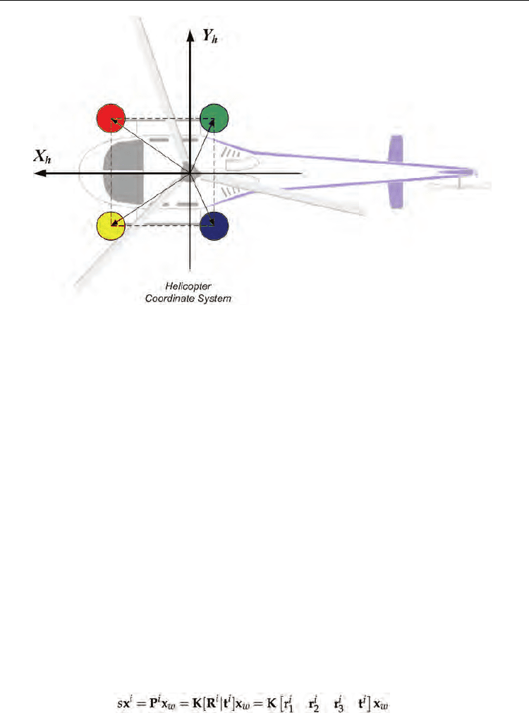
• World and Helicopter Coordinate Systems
The Helicopter Reference System, as described in figure 3, has its origin at the center of mass of
the vehicle and its correspondent axes: X
h
, aligned with the helicopter’s longitudinal axis;
Y
h
, transversal to the helicopter; and Z
h
, pointing down. Considering that the estimation of
the helicopter’s pose with respect to the World Coordinate System is based on the distribution
Visual Servoing for UAVs
193
of the landmarks around the Helicopter Coordinate System, and that the information extracted
from the vision system will be used as reference to the flight controller, a relation between
those coordinate systems has to be found.
In figure 3, it is possible to observe that this relation depends on a translation vector that
defines the helicopter’s position (t), and on a rotation matrix R that defines the orientation of
the helicopter (pitch, roll and yaw angles). Considering that the helicopter is flying at low
velocities (< 4m/s), pitch and roll angles are considered ≈ 0, and only the yaw angle (
θ
) is
taken into account in order to send the adequate commands to the helicopter.
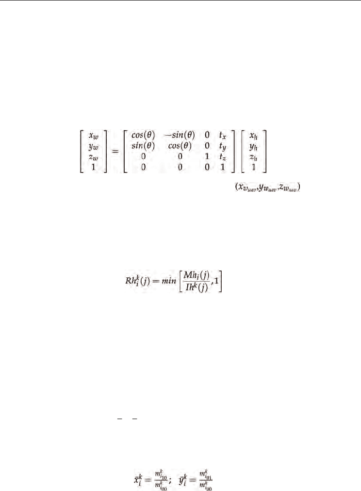
Therefore, the relation of the World and the Helicopter Coordinate Systems can be expressed as
follows:
(17)
Where (t
x
, t
y
, t
z
) will represent the position of the helicopter
with respect to
the World Coordinate System, and
θ
the helicopter’s orientation.
3.1 Feature extraction
The backprojection algorithm proposed by Swain and Ballar in ( Swain & Ballard (1991)) is
used to extract the different landmarks onboard the UAV. This algorithm finds a Ratio
histogram
k
i
Rh
for each landmark i in the k
th
camera as defined in equation 18:
(18)
This ratio
k
i
Rh
represents the relation between the bin j of a model histogram Mh
i
and the
bin j of the histogram of the image Ih
k
which is the image of the k
th
camera that is being
analyzed. Once
k
i
Rh
is found, it is then backprojected onto the image. The resulting image is
a gray-scaled image, whose pixel’s values represent the probability that each pixel belongs
to the color we are looking for.
The location of the landmarks in the different frames are found using the previous-
mentioned algorithm and the Continuously Adaptive Mean Shift (CamShift) algorithm (Bradski
(1998)). The CamShift takes the probability image for each landmark i in each camera k and
moves a search window (previously initialized) iteratively in order to find the densest
region (the peak) which will correspond to the object of interest (colored-landmark i). The
centroid of each landmarks (
k
i
x
,
k
i
y
) is determined using the information contained inside
the search window to calculate the zeroth (
00
k
i
m ), and first order moments (
10
k
i
m ,
01
k
i
m ),
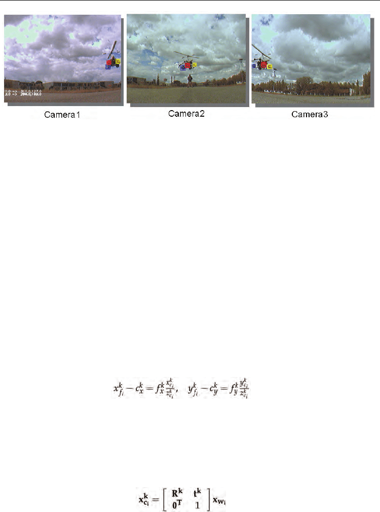
(equation 19). These centroids found in the different images (as presented in figure. 4) are
then used as features for the 3D reconstruction stage.
(19)
When working with overlapping FOVs in a 3D reconstruction process, it is necessary to find
the relation of the information between the different cameras. This process is known as
Visual Servoing
194
Fig. 4. Feature Extraction. Different features must be extracted from images taken by
different cameras. In this example color-based features have been considered.
feature matching. This is a critical process, which requires the differentiation of features in
the same image and also the definition of a metric which tells us if the feature
i in image I
1
is
the same feature
i in image I
2
(image -I- of camera k).
However, in this case, the feature matching problem has been solved taking into account the
color information of the different landmarks; so that, for each image I
k
there is a matrix
×
k
42
F
that will contain the coordinates of the features i found in this image. Then, the features are
matched by grouping only the characteristics found (the central moments of each landmark)
with the same color, that will correspond to the information of the cameras that are seing the
same landmarks.
3.1.1 3D reconstruction
Assuming that the intrinsic parameters (K
k
) and the extrinsic parameters (R
k
and t
k
) of each
camera are known (calculated through a calibration process), the 3D position of the matched
landmarks can be recovered by intersecting in the 3D space the backprojection of the rays
from the different cameras that represent the same landmark.
The relation of the found position of each landmark, expressed in the
Lateral Coordinate
System
(image plane), with the position expressed in the Camera Coordinate System, is defined
as:
(20)
where (
i
k
f
x ,
i
k
f
y
) is the found position of each landmark expressed in the image plane, (
i
k
c
x ,
i
k
c
y
,
i
k
c
z ) represent the coordinates of the landmark expressed in the Camera Coordinate
System
, (
k
x
c ,
k
y
c ) the coordinates of the center of projection in pixel units, and (
k
x
f
,
k
y
f
) the
focal length in terms of pixel dimensions.
If the relation of the 3D position of landmark i with its projection in each Camera Coordinate
System
is defined as:
(21)
Then, integrating equation 21 and equation 20, and reorganizing them, it is possible to
obtain the following equations:
Visual Servoing for UAVs
195
(22)
(23)
Where
i
k
u
x
and
i
k
u
y
represent the coordinates of landmark i expressed in the Central Camera
Coordinate System of the k
th
camera, r
k
and t
k
are the components of the rotation matrix R
k
and
the
translation vector t
k
that represent the extrinsic parameters, and
i
w
x ,
i
w
y
,
i
w
z are the
3D coordinates of landmark i.
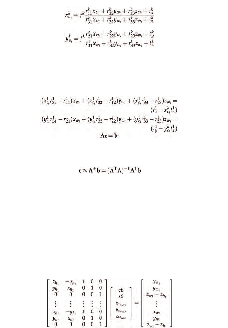
From equations 22 and 23 we have a linear system of two equations and three unknowns
with the following form:
(24)
If there are at least two cameras seeing the same landmark, it is possible to solve the
overdetermined system using the least squares method whose solution will be equation 25,
where the obtained vector c represents the 3D position (
i
w
x
,
i
w
y
,
i
w
z
) of the i
th
landmark:
(25)
Once the 3D coordinates of the landmarks onboard the UAV have been calculated, the
UAV’s position (
uav
w
x ) and its orientation with respect to World Coordinate System can be
estimated using the 3D position found and the landmark’s distribution around the
Helicopter
Coordinate System
(see figure 5). The helicopter’s orientation is defined only with respect to
the Z
h
axis (Yaw angle
θ
) and it is assumed that the angles, with respect to the other axes, are
considered to be ≈ 0 (helicopter on hover state or flying at low velocities < 4
m/s). Therefore,
equation 17 can be formulated for each landmark.
Reorganizing equation 17, considering that c
θ
= cos(
θ
), s
θ
= sin(
θ
),
uav
w
x = t
x
,
uav
w
y = t
y
,
uav
w
z
= t
z
, and formulating equation 17 for all the landmarks detected, it is possible to create
a system of equations of the form Ac = b as in equation 26, with five unknowns: c
θ
, s
θ
,
,
uav
w
x ,
uav
w
y .
uav
w
z If at least the 3D position of two landmarks is known, this system of
equations can be solved as in equation 25, and the solution c is a 4 × 1 vector whose
components define the orientation (
yaw angle) and the position of the helicopter expressed
with respect to a
World Coordinate System.
(26)
Visual Servoing
196
Fig. 5. Distribution of landmarks. The distribution of the landmarks in the
Helicopter
coordinate system
is a known parameter used to extract the helicopter position and
orientation with respect to the
World coordinate system.
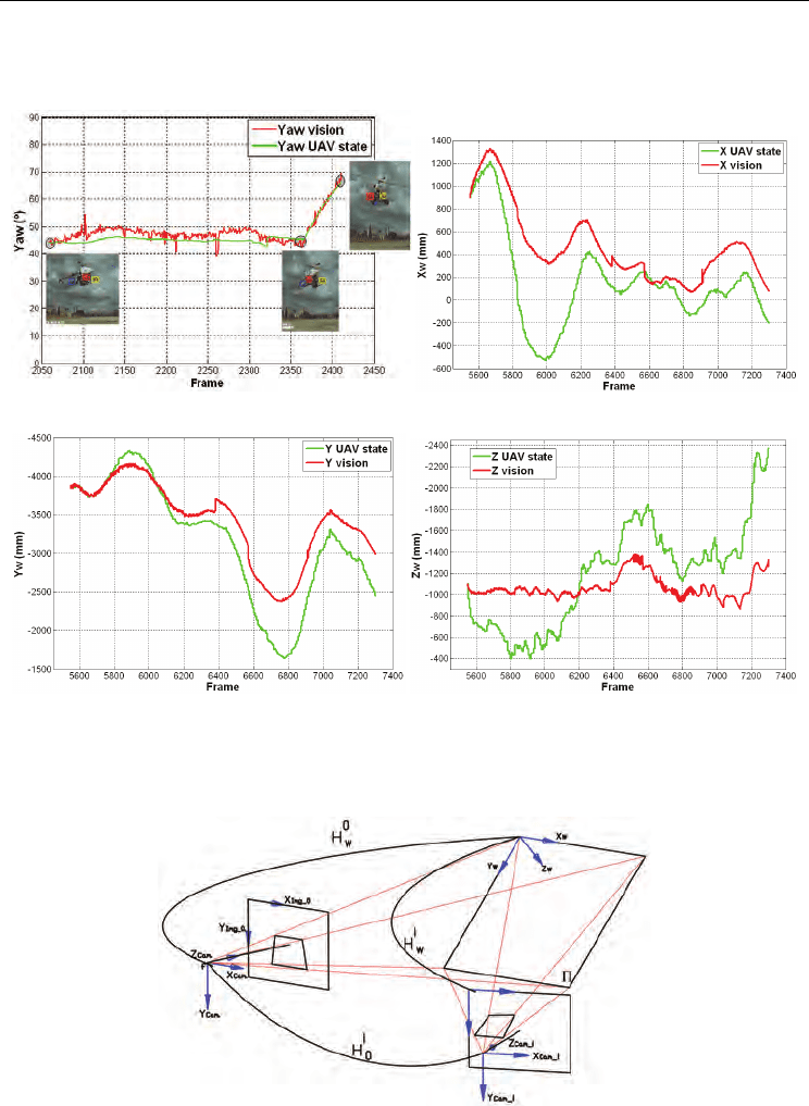
In figures: 6(a), 6(b), 6(c) and 6(d), it is possible to see an example of the UAV’s position
estimation using a ground-based multi camera system (see Martínez et al. (2009) for more
details). In these figures, the vision-based position and orientation estimation (red lines) is
also compared with the estimation obtained by the onboard sensors of the UAV (green
lines).
4. Onboard visual system for pose estimation
In this section, a 3D pose estimation method based on projection matrix and homographies
is explained. The method estimates the position of a world plane relative to the camera
projection center for every image sequence using previous frame-to-frame homographies
and the projective transformation at first frame, obtaining for each new image, the camera
rotation matrix R and a translational vector t. This method is based on the propose by Simon
et. al. (Simon et al. (2000), Simon & Berger (2002)).
4.1 World plane projection onto the Image plane
In order to align the planar object on the world space and the camera axis system, we
consider the general pinhole camera model and the homogeneous camera projection matrix,
that maps a world point x
w
in P
3
(projective space) to a point x
i
on i
th
image in P
2
, defined by
equation 27:
(27)
where the matrix K is the camera calibration matrix, R
i
and t
i
are the rotation and translation
that relates the world coordinate system and camera coordinate system, and
s is an arbitrary
Visual Servoing for UAVs
197
scale factor. Figure 7 shows the relation between a world reference plane and two images
taken by a moving camera, showing the homography induced by a plane between these two
frames.
(a) (b)
(c) (d)
Fig. 6. Vision-based estimation vs. helicopter state estimation. The state values given by the
helicopter state estimator after a
Kalman f ilter (green lines) are compared with a multiple
view-based estimation of the helicopter’s pose (red lines).
Fig. 7. Projection model on a moving camera and frame-to-frame homography induced by a
plane.
Visual Servoing
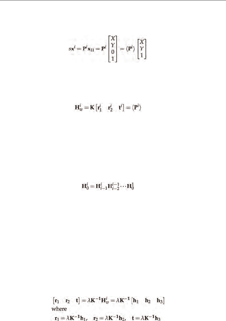
198
If point x
w
is restricted to lie on a plane Π , with a coordinate system selected in such a way
that the plane equation of
Π is Z = 0, the camera projection matrix can be written as equation
28:
(28)
where
〈P
i
〉 denotes that this matrix is deprived on its third column or 〈P
i
〉 = K[
12
rrt
iii
]. The
deprived camera projection matrix is a 3 × 3 projection matrix, which transforms points on
the world plane ( now in
P
2
) to the i
th
image plane (likewise in P
2
), that is none other that a
planar homography
H
i
w
H
iw
defined up to scale factor as equation 29 shows.
(29)
Equation 29 defines the homography which transforms points on the world plane to the
i
th
image plane. Any point on the world plane x
Π
= [x
Π
,y
Π
,1]
T
is projected on the image plane as
x = [x,y,1]
T
. Because the world plane coordinates system is not known for the i
th
image, H
i
w
can not
be directly evaluated. However, if the position of the word plane for a reference
image is known, a
homography
0
H
w
, can be defined. Then, the i
th
image can be related with
the reference image to obtain
the homography
0
H
i
. This mapping is obtained using
sequential frame-to-frame homographies
1−
H
i
i
,
calculated for any pair of frames (i-1,i) and
used to relate the
i
th
frame to the first imagen
0
H
i
using equation 30:
(30)
This mapping and the aligning between initial frame to world plane reference is used to
obtain the projection between the world plane and the
i
th
image H
i
w
=
0
H
i 0
H
w
. In order to
relate the world plane and the
i
th
image, we must know the homography
0
H
w
. A simple
method to obtain it, requires that a user selects four points on the image that correspond to
corners of rectangle in the scene, forming the matched points (0,0) ↔ (
x
1
,y
1
), (0,Π
Width
) ↔
(
x
2
,y
2
), (Π
Lenght
,0) ↔ (x
3
,y
3
) and (Π
Lenght
,Π
Width
) ↔ (x
4
,y
4
). This manual selection generates a
world plane defined in a coordinate frame in which the plane equation of
Π is Z = 0. With
these four correspondences between the world plane and the image plane, the minimal
solution for homography
0
H
w
= [h
1
0
w
h
2
0
w
h
3
0
w
] is obtained using the method described on
section 2.3.1.
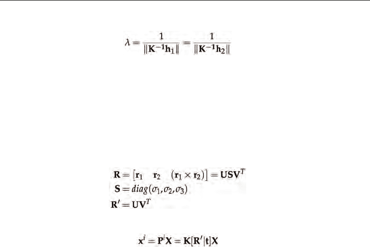
The rotation matrix and the translation vector are computed from the plane to image
homography using the method described in (Zhang (2000)). From equation 29 and defining
the scale factor
λ
= 1/s, we have that:
(31)
Visual Servoing for UAVs
199
The scale factor
λ
can be calculated using equation 32:
(32)
Because the columns of the rotation matrix must be orthonormal, the third vector of the
rotation matrix r
3
could be determined by the cross product of r
1
× r
2
. However, the noise on
the homography estimation causes that the resulting matrix R = [r
1
r
2
r
3
] does not satisfy the
orthonormality condition and we must find a new rotation matrix R’ that best approximates
to the given matrix R according to smallest Frobenius norm for matrices (the root of the sum
of squared matrix coefficients) (Sturm (2000), Zhang (2000)). As demonstrated by (Zhang
(2000)), this problem can be solved by forming the Rotation Matrix R = [r
1
r
2
r
2
] and using
singular value decomposition (SVD) to form the new optimal rotation matrix R’ as equation
33 shows:
(33)
Thus, the solution for the camera pose problem is defined by equation 34:
(34)
4.2 UAV 3D estimation based on planar landmarks
This section shows the use of a pose estimation method based on frame to frame object
tracking using robust homographies. The method, makes a matching between consecutive
images of a planar reference landmark, using either, homography estimation based on good
features to track (Shi & Tomasi (1994)), matched using the pyramidal L-K method, or the
ICIA algorithm (Baker & Matthews (2002)) for an object template appearance tracking using
a homography warping model. The frame to frame matching is used to estimate a projective
transformation between the reference object and the image, using it to obtain the 3D pose of
the object with respect to the camera coordinate system.
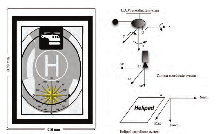
For these tests a Monocromo CCD Firewire camera with a resolution of 640x480 pixels is
used. The camera is calibrated before each test, so the intrinsic parameters are know. The
camera is installed in such a way that it is looking downward with relation to the UAV. A
know rectangular helipad is used as the reference object to which estimate the UAV 3D
position. It is aligned in such a way that its axes are parallel to the local plane North East
axes. This helipad was designed in such a way that it produces many distinctive corner for
the visual tracking. Figure 8(a), shows the helipad used as reference and figure 8(b), shows
the coordinate systems involved in the pose estimation.
The algorithm begins, when a user manually selects four points on the image that
correspond to four points on a rectangle in the scene, forming the matched points (0,0) ↔
(
x
1
,y
1
), (910mm,0) ↔ (x
2
,y
2
), (0,1190mm) ↔ (x
3
,y
3
) and (910mm,1190mm) ↔ (x
4
,y
4
). This
manual selection generates a world plane defined in a coordinates frame in which the plane
equation of
Π is Z = 0 (figure 7) and also defining the scale for the 3D results. With these
four correspondences between the world plane and the image plane, the minimal solution
for homography
0
H
w
is obtained.
Visual Servoing
200
(a) (b)
Fig. 8. 8(a) Helipad used as a plane reference for UAV 3D pose estimation based on
homographies. 8(b) Helipad, camera and U.A.V coordinate systems.
Once the alignment between the camera coordinate system and the reference helipad is
known (
0
H
w
) the homographies between consecutive frames are estimated, using either, the
Pyramidal L.K. or the ICIA algorithm as is described below:
Optical Flow and RANSAC: good features to track are extracted on the zone corresponding
to the projection of the helipad on image
I
0
. Then a new image I
1
is captured, and for
each corner on image
I
0
, the pyramidal implementation of the Lucas Kanade optical
flow method is applied, obtaining for each one either, the corresponding position
(velocity vector) on image
I
1
(if the corresponding point was found on the second
image), or ”null” if it was not found. With these points that have been matched or its
optical flow was found on image
I
1
, a Homography
1
0
H is robustly estimated using the
algorithm described on section ??. Homography
1
0
H
is used to estimate the alignment
between image
I
1
and the reference helipad using
1
H
w
=
1
0
H
0
H
w
, which is used to
obtain the rotation matrix
1
R
w
and the translation vector
1
t
w
using the method
described on section 4.1. Then, the original frame formed by points ((
x
1
,y
1
), (x
2
,y
2
), (x
3
,y
3
)
and (
x
4
,y
4
)) are projected on image I
1
using
1
x
i
I
=
1
0
H
0
x
i
I
, defining the actual position of
the helipad on the image
I
1
. For this position, good features to track are once again
estimated and used to calculate a new set of matched points between images
I
1
and I
2
.
These set of matched points are used to calculate
2
1
H , and then
2
0
H and
2
H
w
from
which
2
R
w
and
2
t
w
is estimated. The process is successively repeated until either, the
helipad is lost or the user finishes the process.