Еврокод 3. Проектирование стальных конструкций. Часть 4-1. Бункеры
Подождите немного. Документ загружается.

χ
x
= 1 −
β
0
0
x
p
η
λ λ
λ λ
−
−
when
0
x p
λ λ λ
< <
... (5.31)
χ
x
=
2
x
α
λ
when
p x
λ λ
≤
... (5.32)
with:
Rcrx
y
x
f
,
σ
λ
=
... (5.33)
0
0,2
λ
= ... (5.34)
1
p
α
λ
β
=
−
... (5.35)
where
α
is chosen as the value of
α
o
,
α
pe
,
α
pp
or
α
L
as appropriate.
NOTE: The National Annex may choose the values of
β
and
η
. The values
β
= 0,60 and
η
= 1,0 are
recommended.
(16) The design buckling membrane stress should be determined as:
σ
x,Rd
=
σ
x,Rk
/
γ
M1
... (5.36)
where
γ
M1
is given in 2.9.2.
(17) At every point in the structure the design stress resultants should satisfy the condition:
n
x,Ed
≤ t
σ
x,Rd
... (5.37)
(18) Where the wall contains a lap joint satisfying the conditions defined in (12), the measurement
of the maximum permissible measurable imperfection need not be taken across the lap joint itself.
(19) The design of the shell against buckling under axial compression above a local support, near a
bracket (e.g. to support a conveyor gantry), and near an opening should be undertaken as stipulated in
5.6.
5.3.2.5 Buckling under external pressure, internal partial vacuum and wind
(1) The buckling assessment should be carried out using EN 1993-1-6, but these may be met using
the following assessments of the design resistance.
(2) The lower edge of the cylindrical shell should be effectively anchored to resist vertical
displacements, see 5.4.7.
(3) Under wind or partial vacuum, the silo wall should be broken into segments lying between
stiffening rings or changes of plate thickness or boundary conditions.
EN 1993-4-1:2007 (Е)
36
(4) A buckling assessment should be carried out on each segment or potential group of segments
where a buckle could form, including the thinnest segment and adding others progressively. The
lowest design buckling pressure should be found from these alternative assessments.
(5) The critical buckling external pressure for an isotropic wall should be found as:
p
n,Rcru
= 0,92 C
b
C
w
E
2,5
r t
l r
... (5.38)
where:
t is the thickness of the thinnest part of the wall;
l i
s the height between stiffening rings or boundaries;
C
b
is the external pressure buckling coefficient;
C
w
is the wind pressure distribution coefficient.
(6) The parameter C
b
should be evaluated based on the condition at the upper edge according to
table 5.2.
Table 5.2 Values of external pressure buckling parameter C
b
Upper edge
condition
Roof integrally
structurally
connected to wall
(continuous)
Upper edge ring
satisfying
5.3.2.5 (12)-(14)
Upper edge not
satisfying
5.3.2.5 (12)-(14)
C
b
1,0 1,0 0,6
(7) Where the silo is in a close-spaced silo group, the wind pressure distribution coefficient
(relating to the pressure at the windward generator of the silo) should be taken as C
w
= 1,0.
(8) Where the silo is isolated and subject only to wind loading, the wind pressure distribution
coefficient (relating to the pressure at the windward generator of the silo) should be taken as the
greater of:
2,2
1 0,1
w
b
C
r r
C
l t
=
+
... (5.39)
C
w
= 1,0 ... (5.40)
(9) Where the silo is isolated and a combination of wind loading and internal vacuum exist, the
value of C
w
should be determined as a linear combination of 1,0 and the calculated value given in
(8), according to the proportions of the external pressure that arise from each source.
(10) The design maximum external pressure (windward generator) under wind and/or partial vacuum
should be assessed as:
p
n,Rd
= α
n
p
n,Rcru
/
γ
M1
... (5.41)
where α
n
is the elastic buckling imperfection reduction factor and
γ
M1
is given in 2.9.2.
EN 1993-4-1:2007 (Е)
37

NOTE: The National Annex may choose the value of
α
n
. The value
α
n
= 0,5 is recommended.
(11) The resistance check should satisfy the condition:
p
n,Ed
≤ p
n,Rd
... (5.42)
where:
p
n,Ed
is the design value of the maximum external pressure under wind and/or partial
vacuum.
(12) For the upper edge of a cylinder to be treated as effectively restrained by a ring, the ring should
satisfy both a strength and a stiffness requirement. Unless a more thorough assessment is made using
numerical analysis, the design value of the circumferential (hoop) force and circumferential bending
moment about a vertical axis in the ring should be taken as:
N
θ,Ed
= 0,5 r L p
n,Ed
... (5.43)
M
θ,Ed
= M
θ,Edo +
M
θ,Edw
... (5.44)
with:
M
θ,Edo
= 0,0033 p
nS1
r
2
L
1
1 ,
( )
nS
nS n Edu
p
p p−
... (5.45)
M
θ,Edw
= 0,17 p
n,Edw
r
2
L
,
1 ,
n Edu
nS n Edu
p
p p
−
... (5.46)
p
nS1
=
3
6
z
EI
r L
... (5.47)
where:
p
n,Edu
is the design value of the uniform component of the external pressure under wind
and/or partial vacuum;
p
n,Edw
is the design value of the stagnation point pressure under wind;
p
nS1
is the reference pressure for ring bending moment evaluations;
M
θ,Edo
is the design value of the bending moment associated with out-of-roundness;
M
θ,Edw
is the design value of the bending moment due to wind;
I
z
is the second moment of area of the ring for circumferential bending;
L is the total height of the shell wall;
t is the thickness of the thinnest strake.
(13) Where the ring at the upper edge of a cylinder is made as a cold formed construction, the value
of M
θ,Edo
should be increased by 15% above that given by expression 5.45.
EN 1993-4-1:2007 (Е)
38

(14) The flexural rigidity EI
z
of a ring at the upper edge of the cylinder about its vertical axis
(circumferential bending) should exceed the larger of:
EI
z,min
= k
1
E Lt
3
... (5.48)
and
EI
z,min
= 0,08 C
w
E r t
3
(r/t) ... (5.49)
where C
w
is the wind pressure distribution coefficient given in (7) or (8).
NOTE: The National Annex may choose the value of k
1
.
The value k
1
= 0,1 is recommended.
5.3.2.6 Membrane shear
(1) Where a major part of the silo wall is subjected to shear loading (as with eccentric filling,
earthquake loading etc.), the membrane shear buckling resistance should be taken as that for a shell in
torsion at each horizontal level. The axial variation in shear may be taken into account in design.
(2) The critical shear buckling stress of the isotropic wall should be calculated as:
τ
xθ,Rcr
=
0,5 1,25
0,75
r t
E
l r
... (5.50)
where:
t is the thickness of the thinnest part of the wall;
l is the height between stiffening rings or boundaries.
(3) A stiffening ring which is required as the boundary for a shear buckling zone should have a
flexural rigidity EI
z
about the axis for bending around the circumference not less than:
EI
z,min
= k
s
E t
3
rl ... (5.51)
where the values of
l
l
and t are taken as the same as those used in the most critical buckling mode in
paragraph (2).
NOTE: The National Annex may choose the value of k
s
. The value k
s
= 0,10 is recommended.
(4) Where the shear
τ
varies linearly with height in the structure, the critical shear buckling
resistance at the point of highest shear may be increased to:
τ
xθ,Rcr
=
0,5
1,25
0
1, 4
r t
E
l r
... (5.52)
with
l
o
determined from:
l
o
=
, ,max
,
x Ed
x Ed
d
dx
θ
θ
τ
τ
... (5.53)
EN 1993-4-1:2007 (Е)
39
where
,x Ed
d
dx
θ
τ
is the axial rate of change of shear with height averaged over the zone and
τ
xθ,Ed,max
is the peak value of shear stress. Where the length
l
ll
l
o
exceeds the height of the structure, this
rule should not be used, but the shell should be treated as subject to uniform membrane shear set out
in (2).
(5) Where local shear stresses are induced by local supports and load-bearing axial stiffeners, the
critical shear buckling resistance, assessed in terms of the local value of the shear transfer between the
axial stiffener and the shell may be evaluated at the point of highest shear as:
τ
xθ,Rcr
=
0,5
1,25
0
1, 4
r t
E
l r
... (5.54)
in which
l
o
is found as:
l
l
o
=
, ,max
,
x Ed
x Ed
d
dx
θ
θ
τ
τ
(5.55)
where
,x Ed
d
dy
θ
τ
is the circumferential rate of change of shear with distance from the stiffener
averaged over the zone, and
τ
xθ,Ed,max
is the peak value of shear stress.
(6) The design buckling stress should be determined as the lesser of:
τ
xθ,Rd
=
α
τ
τ
xθ,Rcr
/
γ
M1
... (5.56)
and
τ
xθ,Rd
= 0,57 f
y
/
γ
M1
... (5.57)
where:
α
τ
is the elastic buckling imperfection reduction factor;
γ
M1
is the partial factor given in 2.9.2.
NOTE: The National Annex may choose the value of
α
τ
. The value
α
τ
= 0,80 is recommended.
(7) At every point in the structure the design stress resultants should satisfy the condition:
n
xθ,Ed
≤ t
τ
xθ,Rd
... (5.58)
5.3.2.7 Interactions between meridional compression, circumferential compression and
membrane shear
(1) Where the stress state in the silo wall contains significant components of more than one
com
pressive membrane stress or shear stress, the provisions of EN 1993-1-6 should be followed.
(2) The requirements of this interaction may be ignored if all but one of the design stress
components are less than 20% of the corresponding buckling design resistance.
EN 1993-4-1:2007 (Е)
40
5.3.2.8 Fatigue, LS4
(1) For silos in Consequence Class 3, the provisions of EN 1993-1-6 should be followed.
(2) For silos in Consequence Class 2, a fatigue check should be carried out if the design life of the
structure involves more than N
f
cycles of filling and discharge.
NOTE: The National Annex may choose the value of N
f
. The value N
f
= 10 000 is recommended.
5.3.2.9 Cyclic plasticity, LS2
(1) For silos in Consequence Class 3, the provisions of EN 1993-1-6 should be followed. A check
for failure under cyclic plasticity should be made at discontinuities, near local ring stiffeners and near
attachments.
(2) Silos in other Consequence Classes, this check may be omitted.
5.3.3 Isotropic walls with vertical stiffeners
5.3.3.1 General
(1) Where an isotropic wall is stiffened by vertical (stringer) stiffeners, the effect of compatibility
of the shortening of the wall due to internal pressure should be taken into account in assessing the
vertical compressive stress in both the wall and the stiffeners.
(2) The design stress resultants, resistances and checks should be carried out as in 5.3.2, but
including the additional provisions set out here.
5.3.3.2 Plastic limit state
(1) The resistance against rupture on a vertical seam should be determined as for an isotropic shell
(5.3.2).
(2) Where a structural connection detail includes the stiffener as part of the means of transmitting
circumferential tensions, the effect of this tension on the stiffener should be taken into account in
evaluating the force in the stiffener and its susceptibility to rupture under circumferential tension.
5.3.3.3 Buckling under axial compression
(1) The wall should be designed for the same axial compression buckling criteria as the unstiffened
wall unless the stiffeners are at closer spacings than 2
rt, where t is the local thickness of the wall.
(2) Where vertical stiffeners are placed at closer spacings than 2 rt, the buckling resistance of the
complete wall should be assessed either by assuming that paragraph (1) above applies, or by using the
global analysis procedures of EN 1993-1-6.
(3) The axial compression buckling strength of the stiffeners themselves should be evaluated using
the provisions of EN 1993-1-1 or EN 1993-1-3 (cold formed steel members) or EN 1993-1-5 as
appropriate.
(4) The eccentricity of the stiffener to the shell wall should be taken into account.
5.3.3.4 Buckling under external pressure, partial vacuum or wind
(1) The wall should be designed for the same external pressure buckling criteria as the unstiffened
wa
ll unless a more rigorous calculation is necessary.
EN 1993-4-1:2007 (Е)
41

(2) Where a more rigorous calculation is needed, the vertical stiffeners may be smeared to give an
orthotropic wall, and the buckling stress assessment carried out using the provisions of 5.3.4.5, with
C
φ
= C
θ
= Et and C
φθ
= 0,38 Et.
5.3.3.5 Membrane shear
(1) Where a major part of the silo wall is subjected to shear loading (as with eccentric filling,
earthquake loading etc.), the membrane shear buckling resistance should be found as for an isotropic
unstiffened wall (see 5.3.2.6), but the calculated resistance may be increased if account is taken of the
effect of the stiffeners. The equivalent length
l
l
of shell in shear may be taken as the lesser of the
height between stiffening rings or boundaries and twice the horizontal separation of the vertical
stiffeners, provided that each stiffener has a flexural rigidity EI
y
for bending in the vertical direction
(about a circumferential axis) greater than:
EI
y,min
= k
s
E t
3
rl ... (5.59)
where the values of
l
and t are taken as the same as those used in the most critical buckling mode.
NOTE: The National Annex may choose the value of k
s
. The value k
s
= 0,10 is recommended.
(2) Where a discrete stiffener is abruptly terminated part way up the shell, the force in the stiffener
should be taken to be uniformly redistributed into the shell over a length not exceeding k
t
rt.
NOTE: The National Annex may choose the value of k
t
. The value k
t
= 4,0 is recommended.
(3) Where the stiffeners are terminated as in (2), or used to introduce local forces into the shell, the
assessed resistance for shear transmission between the stiffener and the shell should not exceed the
value given in 5.3.2.6 for linearly varying shear.
5.3.4 Horizontally corrugated walls
5.
3.4.1 General
(1) All calculations should be carried out with thicknesses exclusive of coatings and tolerances.
(2) The minimum steel core thickness for the corrugated sheeting of the wall should meet the
requirements of EN 1993-1-3. In bolted construction, the bolt size should not be less than M8.
(3) Where the cylindrical wall is fabricated from corrugated sheeting with the corrugations running
horizontally and vertical stiffeners are attached to the wall, the corrugated wall should be assumed to
carry no vertical forces unless the wall is treated as an orthotropic shell, see 5.3.4.3.3.
(4) Particular attention should be paid to ensure that the stiffeners are flexurally continuous with
respect to bending in the meridional plane normal to the wall, because the flexural continuity of the
stiffener is essential in developing resistance to buckling under wind or external pressure as well as
when the stored solids flow.
(5) Where the wall is stiffened with vertical stiffeners, the fasteners between the sheeting and
stiffeners should be proportioned to ensure that the distributed shear loading from stored solids
(frictional traction) on each part of the wall sheeting is transferred into the stiffeners. The sheeting
thickness should be chosen to ensure that local rupture at these fasteners is prevented, taking proper
account of the reduced bearing strength of fasteners in corrugated sheeting.
EN 1993-4-1:2007 (Е)
42
(6) The design stress resultants, resistances and checks should be carried out as in 5.3.2, but
including the additional provisions set out in (1) to (5) above.
NOTE 1: More detailed information on the design of corrugated silos is available in the references
given in Annex D.
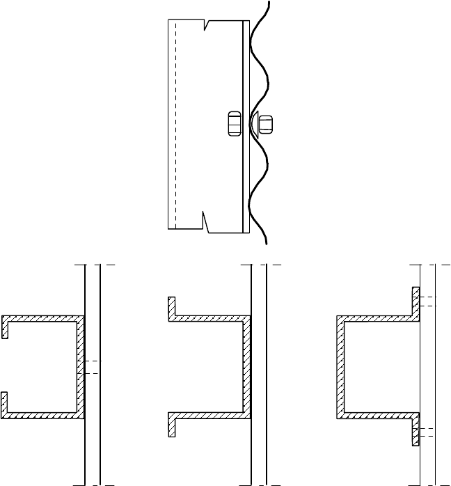
NOTE 2: Common arrangements for stiffening the wall are shown in figure 5.3.
Figure 5.3: Common arrangements for vertical stiffeners on horizontally
corrugated shells
5.3.4.2 Plastic limit state
(1) Bolts for fastenings between panels should satisfy the requirements of EN 1993-1-8.
(2) The joint detail between panels should comply with the provisions of EN 1993-1-3 for
connections in tension or compression.
(3) The spacing between fasteners around the circumference should not exceed 3° of the
circumference.
NOTE: A typical bolt arrangement detail for a panel is shown in figure 5.4.
EN 1993-4-1:2007 (Е)
43
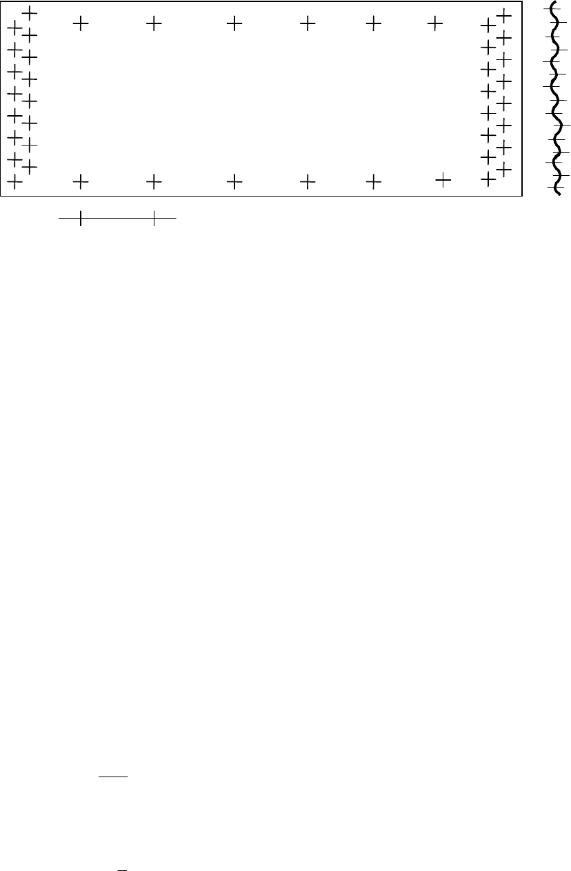
< 500 mm
Figure 5.4: Typical bolt arrangement for a panel of a corrugated silo
(4) Where penetrations are made in the wall for hatches, doors, augers or other items, a thicker
corrugated sheet should be used locally to ensure that the local stress raisers associated with
mismatches of stiffness do not lead to local rupture.
5.3.4.3 Buckling under axial compression
5.3.4.3.1 General
(1) Under axial compression, the design resistance should be determined at every point in the shell
using the prescribed fabrication tolerance quality of construction, the intensity of the guaranteed co-
existent internal pressure p and the circumferential uniformity of the compressive stress. The design
should consider every point on the shell wall.
(2) If the horizontally corrugated wall is stiffened with vertical stiffeners, the buckling design of
the wall should be carried out using one of two alternative methods:
a) buckling of the equivalent orthotropic shell (following 5.3.4.3.3) if the horizontal
distance between stiffeners satisfies 5.3.4.3.3 (2);
b) buckling of the individual stiffeners (corrugated wall assumed to carry no axial force, but
providing restraint to the stiffeners) and following 5.3.4.3.4 if the horizontal distance
between stiffeners does not satisfy 5.3.4.3.3 (2).
5.3.4.3.2 Unstiffened wall
(1) If the corrugated shell has no vertical stiffeners, the characteristic value of local plastic buckling
re
sistance should be determined as the greater of:
2
,
2
y
x Rk
t f
n
d
= ... (5.60)
and
,
x Rk y
t
n R f
r
φ
= ... (5.61)
where:
EN 1993-4-1:2007 (Е)
44

t is the sheet thickness;
d is the crest to trough amplitude;
R
φ
is the local curvature of the corrugation (see figure 4.2);
r is the cylinder radius.
The local plastic buckling resistance n
x,Rk
should be taken as independent of the value of internal
pressure p
n
.
NOTE: The local plastic buckling resistance is the resistance to corrugation collapse or “roll-down”.
(2) The design value of the local plastic buckling resistance should be determined as:
n
x,Rd
= α
x
n
x,Rk
/
γ
M0
... (5.62)
where:
α
x
is the elastic buckling imperfection reduction factor;
γ
M0
is the partial factor given in 2.9.2.
NOTE: The National Annex may choose the value of
α
x
. The value
α
x
= 0,80 is recommended.
(3) At every point in the structure the design stress resultants should satisfy the condition:
n
x,Ed
≤ n
x,Rd
... (5.63)
5.3.4.3.3 Stiffened wall treated as an orthotropic shell
(1) If the wall is treated as an orthotropic shell (method (a) in 5.3.4.3.1), the stiffnesses of the
sheeting in different directions should be taken from 4.4. The resulting smeared stiffnesses should be
taken to be uniformly distributed. The equivalent shell middle surface should be taken as the central
axis from which the amplitude is measured (see Fig. 4.2).
(2) The horizontal distance between stiffeners d
s
should not be more than d
s,max
given by:
0,25
2
,max
y
s dx
y
r D
d k
C
=
... (5.64)
where:
D
y
is the flexural rigidity per unit width of the thinnest sheeting parallel to the
corrugations;
C
y
is the stretching stiffness per unit width of the thinnest sheeting parallel to the
corrugations;
r is the cylinder radius.
NOTE: The National Annex may choose the value of k
dx
. The value k
dx
= 7,4 is recommended.
EN 1993-4-1:2007 (Е)
45