Davim J. Paulo (editor). Machining. Fundamentals and Recent Advances
Подождите немного. Документ загружается.

Sculptured Surface Machining 231
lems. The algorithms used in these systems are explained in their theoretical
manuals, and abundant technical information about them is also available [6].
There are also CAM software packages specifically focussed on special applica-
tions, for example impellers and other turbo-machinery components.
From the CAM user’s point of view, the main trouble during tool path genera-
tion appears in the post-processing step, when the tool path generated by the CAM
is translated into a CNC code for a particular five-axis machine. For example, a
machine with the two rotary additional axes in the bed is very different from those
with two orientation angles (the twist and tilt angles) in the spindle head. The
same part and even the same automatically programmed tool (APT) code obtained
from CAM leads to very different CNC codes for each of these.
Another real risk is tool collision during milling. Collisions can damage the
weak hybrid bearings of the high-speed spindle (these bearings are composed of
steel races with ceramic balls), involving high repair costs and long off-production
times. Even if the machine’s spindle is not damaged, it must be remembered that
the five-axis process is usually applied on complex and high added-value parts,
such as impellers made of titanium or super-alloys, or near net shape precision
cast parts; therefore, machining errors can also damage the workpiece, wasting a
lot of previous machining time and expensive raw material.
As explained in [2] for the three-axis machining of complex surfaces, in five-
axis milling, a new approach to the CAM stage must be applied, improving the
reliability of the whole process. Here the definition of reliability is achieving good
productivity with low risk to parts out of tolerances or with irrecoverable errors. In
five-axis milling, the CAM is the centre of gravity of the planning process. Work-
shop workers can only change the actual values of the cutting speed and feed rate,
making use of the machine dials (which modify the actual feed and spindle rota-
tion speed with respect to those programmed in the CNC code); it is not possible
for them to change the complex tool path directly in the CNC interface. A new
intelligent CAM procedure is presented below. This production scheme includes a
scientific model to evaluate the cutting forces.
8.3 The CAM, Centre of Complex Surfaces Production
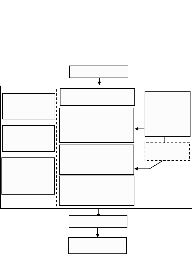
In Figure 8.4, a reliable scheme for CAM and process planning for three- and five-
axis milling is proposed. The commercial CAM software achieves the common
requirements for three- and five-axis machining to define tool paths on the ma-
chined surfaces. For this purpose, machining strategies, such as zig-zag, z-level,
rest milling and by-user definition of the intol and outol parameters, are provided.
However, new concepts are included in the five-axis scheme compared to the
three-axis one.
Thus, there is the possibility of using new finishing strategies for applying five-
axis milling, which allows improvements in precision and quality of complex
surfaces. For example, using bitangencies in corners achieves a better use of the
tool cutting edge in the finishing of sharp surfaces. The selection of the tool-axis
angle with respect to the surface to be machined and the feed direction with re-
232 L.N. López de Lacalle and A. Lamikiz
spect to the reference line are parameters that the CAM operator freely chooses.
Commercial software allows the user to define different values for these angles,
but no recommendation is given about how to do so correctly. In a published anal-
ogy [7], a cutting force estimation model is presented as an analysis utility for the
best selection of the minimal force tool path in three-axis machining, a problem
similar to the climber’s choice of the best path for scaling a mountain. A climber
will choose a climbing path depending on his or her training, but the ascent will
require a great effort, regardless. However, in five-axis milling, the mountaineer
(the CAM operator) can knock the mountain down to reach the peak.
Based on the above observations, some recommendations have been introduced
into the CAM scheme for prior selection of tool-surface orientation. Tilt and lead
angles of tools related to surface and machining direction, respectively, can be
pre-selected to reduce cutting forces. This point is elaborated on in Section 8.6 and
is shown as a module ( f ) in Figure 8.4.
Figure 8.4. Proposed work planning for CAM in five-axis milling
Programming of
rough tool paths
Programming of
semi-finishing
tool paths:
zig-zag
Programming of
electrode
Tool path
Programming of semi-finish-
ing tool paths (b):
-helicoidal z milling
-rest milling
-bitangential milling
Programming of finishing
toolpaths (c):
-helicoidal z milling
-special strategies
Virtual simulation of
milling (d)
-detection of tool collisions
-feed optimisation
Cutting forces
estimator (f)
CAM till 1999
New work
schema
Complex surface
machining
Definition of
cutting
parameters (e)
V
c
, N, z, a
p
, a
e
assistant
Post-processing (g)
Programming of roughing tool
paths (a)
CAD surface model
Sculptured Surface Machining 233
The next step after tool path generation is post-processing, presenting those
problems and features explained in the previous section. The post-processor defi-
nition is a difficult task needing a great knowledge of the postprocessor generator
utility and of the machine tool itself.
After post-processing, the next step is tool path verification. Strongly recom-
mended in three-axis milling, this step becomes essential in the case of five-axis
machines. Available software systems (Vericut™, Predator™, etc.) allow the user
to perform a virtual simulation before actual machining, allowing detection and
correction of problems, as follows:
• Collisions and interferences between tool and part, toolholder and part, or
even between spindle head and machine bed.
• Problems from the tool gouging into the workpiece, an important aspect of
the machining of corners.
The output of the virtual verification is a list of collisions, interferences, and detec-
tions of bad cuts (milling under the theoretical CAD surface or uncut overstocks).
After the list examination, changes in the CAM tool paths are done by the CAM
operator, generating a new CNC program free of interferences. However, the re-
sult is far from a true reliable tool path. Virtual simulation takes into account only
geometric collisions, and problems from the cutting process itself are not revealed.
In spite of these limitations, the virtual simulation is a powerful tool for achieving
a good machining process, allowing very fast pre-process error detection. Nowa-
days, the trend is to include virtual simulation inside the CAM software, or to in-
clude a direct link from CAM to other partner software programs for verification.
Finally, the machining of the workpiece will be performed. Even with a correct
previous simulation, this step leads to its own problems: wrong cutting parameters
or an incorrect tool selection can lead to bad results, even with correct CAM tool
paths. CAM operators can select cutting parameters based on the recommenda-
tions from tool manufacturers’ databases (module e in Figure 8.4), or based on the
historical background collected in the company’s database. In aluminium and
other light alloys, this procedure is enough to define good cutting conditions.
However, in the cases of tempered steels (for moulds), heat-resistant alloys (im-
pellers and blades) and titanium alloys (blades and frame components), cutting
conditions usually calculated only for good tool life are not optimal. Other aspects
such as tool deflection, which directly influences parts precision and roughness,
are more important. Tool deflection is directly related to the cutting forces that are
going to be calculated and offered as information to the CAM user (Section 8.6).
This CAM scheme has been implemented in several small and medium-size en-
terprise (SME) companies in the Basque Country of Spain. Waste part reductions
of 20% (and even 35% in the best case) have been reported since 2003.
8.4 Workpiece Precision
Dimensional errors on sculptured surfaces depend on the chordal error applied by
CAM, the machine-tool kinematic errors, the tool deflection caused by the cutting
234 L.N. López de Lacalle and A. Lamikiz
forces and on the delay error of the CNC along curve interpolation. A complete
study of the stiffness chain of the global system has been presented in two publica-
tions, one [8] for the conventional scale and one [9] for micromilling (machine,
toolholder and tool), giving the following figures for the former scale:
• The machine stiffness, measured as the displacement of the spindle nose
with regard to the machine bed due to a force, can be obtained by experi-
mental or finite element tests. Typical values are about 30–62 N/μm in X,
30–40 N/μm in Y, and 67–95 N/μm in Z (vertical machining centres).
• The most common shank/toolholder is the HSK 63 type. Radial stiffness of
these shanks ranges from 25 N/μm at 5,000 rpm to 20 N/μm at 25,000
rpm.
• With respect to tools, 0.15 N/μm for 6∅ mm, 4.4 N/μm for 12∅ mm, and
1.6 N/μm for 16∅ mm were measured at the tool tip. Even in the best case
(12∅ mm), tool stiffness is approximately four times less than the shank.
Usual models for tool deflection consider it as a cylindrical cantilever
beam. Then, deflection conforms to the equation:
4
3
64
D
L
E
F
3
π
δ
=
(8.1)
where E is the Young’s modulus for tool material, and L
3
/D
4
is the tool
slenderness parameter, where D is the equivalent tool diameter and L is the
overhang length. F is the cutting force component perpendicular to the tool
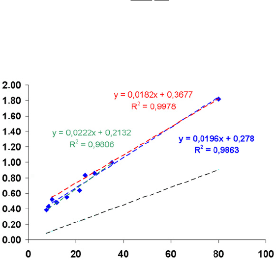
Figure 8.5. Approximate extrapolation lines for stiffness coefficients: lines for shank with
cylindrical collet (SCC) and shank with tapered collet (STC), line common to all cases and
lines of the cantilever beam case
Flexibility coeficient Cp (μm/N)
Common line
Line SCC
Line STC
Cantilever beam line
Tool slenderness (L
3
/D
4
)
Sculptured Surface Machining 235
axis and contained on the plane composed by the tool axis and the normal
to surface at the cutting point, called the deflection force hereinafter. The
Young’s modulus of micrograin-grade carbide tools sintered with 10–12%
cobalt is approximately 6 × 10
5
N/mm² (three times stiffer than steel).
This model is good enough to explain qualitative aspects but overlooks the effects of
the machine itself and the toolholder. Some useful values have been proposed for
the whole system in [8,
10] (see also Figure 8.5), in which the user can approxi-
mate tool tip flexibly for typical tapered or cylindrical collet shanks, and values of
L
3
/D
4
. The flexibility is an input for the deflection estimation of a particular tool.
Natural frequencies of the spindle-tool assembly for three- and five-axis ma-
chining centres were measured for obtaining and checking the stability lobes of
machining operations. For a typical case, the value of the low frequencies was 436
and 1115 Hz on the X-axis and 430, 720, and 1110 Hz on the Y-axis. These values,
along with the small cut depth of finishing, avoid dynamic problems such as chat-
ter in high-speed finishing of moulds, dies and other complex free-forms.
8.4.1 Cutting Forces
Cutting forces are a function of various factors, including tool geometry, work
material, workpiece geometry, cutting conditions and the sense of machining with
respect to the surface. Forces vary greatly with the machining strategy, both in
magnitude and direction. Dimensional error on the surface also depends on the
value and direction of the deflection (see Equation (8.1)).
Some research has focussed on the estimation of cutting forces [11–14]. Basi-
cally there are three approaches:
• The finite element method: the complexity of the three-dimensional (3D)
cutting model requires a long computation time that renders this model
type untenable for real-time calculations. These models are interesting for
tool design or for hypothesis or results interpretation in research projects
about machining.
• A mechanistic model for the cutting forces calculus, along with a solid
modeller to define the swept volume at each surface point [15].
• A mechanistic model as in the previous case, but including the effect of the
part slope through geometrical considerations. This has been well ex-
plained previously [16,
17].
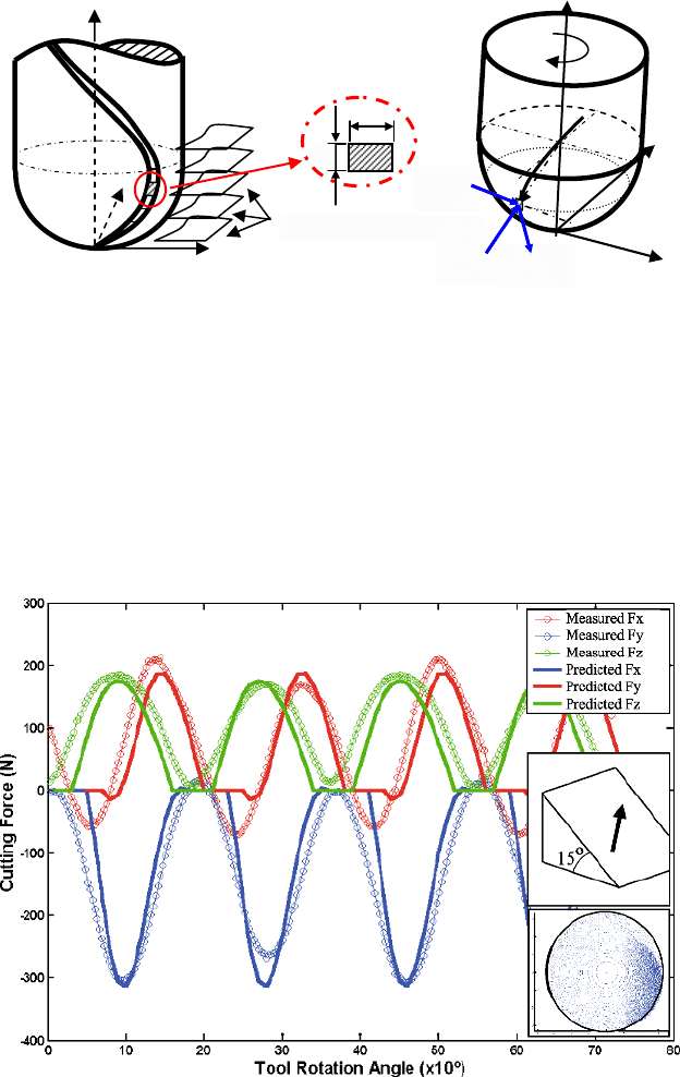
Figure 8.6 provides a brief explanation of this last model. Cutting force can be calcu-
lated as a combination of the shear and ploughing cutting force components, based on
the expressions presented by Lee and Altintas [18]. The tangential, radial and binor-
mal components are calculated at each edge point as shown in Equation (8.2).
() ( )
() ( )
() ( )
θΨθκ
θΨθκ
θΨθκ
=+⋅
⎧
⎪
=+⋅
⎨
⎪
=+⋅
⎩
ttetcn
rrercn
aaeacn
dF ,z K dS K t , , db
dF ,z K dS K t , , db
dF ,z K dS K t , , db
(8.2)
236 L.N. López de Lacalle and A. Lamikiz
Figure 8.6. The basis of the mechanistic model for cutting force estimation: discretization
of the cutting edge, calculus of the chip section, and forces at each discrete edge element
where dF
t
, dF
r
, dF
a
(in N) are the tangential, radial, and axial components; K
tc
,
K
rc
, and K
ac
(in N/mm
2
) are the shear-specific coefficients; K
te
, K
re
, K
ae
(in N/mm)
are the edge-specific coefficients; dS (mm) is the length of each discrete element
of the cutting edge; t
n
(in mm) is the undeformed chip thickness; and db (mm) is
the chip width in each cutting edge discrete element. Therefore, it is necessary to
calculate the undeformed chip thickness and the length of each discrete element of
the cutting edge, which requires geometrical modelling of the tool.
Figure 8.7. Measured and estimated forces for a test on steel AISI H13 to 52 HRC using
a 45° upward feed sense strategy on a 15° slope, a
p
=
1 mm, f
z
=
0.032 mm. Image of the
tool engagement into material
Z
j
Flute
Y
t
n
X
i Element
db
z
constant planes
X
Y
Z
d
F
r
dF
a
R
0
N
dF
t

Sculptured Surface Machining 237
A coordinate transformation is applied to introduce the case of slope milling.
Thus, the force over each cutting edge discrete element is obtained, and finally the
resulting force is determined by the numerical sum along the edge engaged with
the material, simultaneously taking into account the teeth that are cutting. One
result for a milling test of a 15° slope is presented in Figure 8.7.
For calculating the specific cutting coefficients, a set of experimental tests has
to be carried out. Forces experimentally measured during these tests are used as
input data, together with the cutting parameters (a
p
, a
e
, Vc, fz) of each test, to ob-
tain the model specific coefficients. The calculation is based on an inverse method
of the force model used.
There are differences regarding the kind of specific coefficients to be used. The
simpler models use constant coefficients, but these are only valid for end mills.
A usual approach is to calculate the force coefficients by obtaining a function
capable of fitting the force values measured in the set of characterization tests;
these are the typical polynomial functions (with different degrees). Polynomials
depend on the undeformed chip thickness or the z position of each cutting edge
element. For example, Feng and Menq [11] applied cubic polynomial shear coeffi-
cients with good results. Regarding models that introduce the ploughing cutting
coefficients, only Engin and Altintas [12] have introduced z-dependent quadratic
coefficients for inserted milling cutters. In Lamikiz et al. [16], these z-linear shear
and constant ploughing coefficients are demonstrated as sufficiently precise.
8.5 Workpiece Roughness
In finishing, not only good accuracy but also good roughness levels must be
achieved. Theoretical roughness (Figure 8.8) for a ball-end milling operation con-
forms to the equation
2
84
α
=−
tt
P ( ·R·R R ) cos (8.3)
Here P (named step, similar to a
e
) is the radial width of cut, R is the tool radius,
R
t
is the maximum theoretical roughness (R
t
is similar to C, the scallop height) and
α is the slope of the surface (in the direction in which the step P is increased).
However, in practice there are other factors, such as vibration, material plasticity
and tool deflection, which affect the values predicted by Equation (8.3), causing
roughness that is perhaps 20–30% greater.
The estimation of real topography remains a research issue [19–21]. However, in
many industrial cases, the exact prediction of roughness may not be so useful because
of the final by-hand polishing usually performed, or alternative finishing opera-
tions such as ball burnishing [22] or in some very particular cases laser or chemi-
cal polishing. The former has been successfully applied for complex surfaces [22].
The burnishing devices recommended for die and moulds are based on a hydro-
static spring, whose main advantage is that the ball load is constant during the process
and related to the maximum pressure survey by an external pump. This is a high-
pressure pump with low flow, taking coolant up from the machine-tool reservoir.
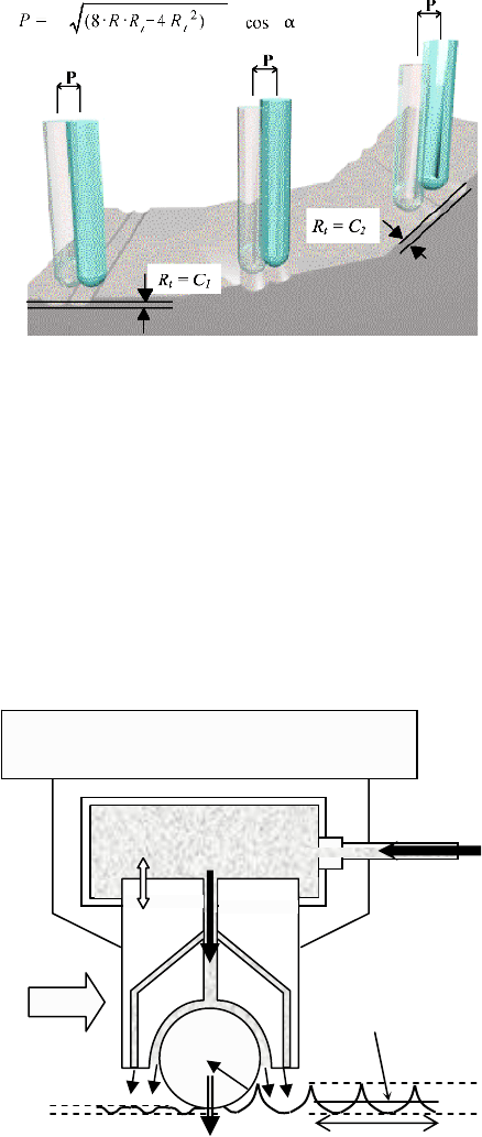
238 L.N. López de Lacalle and A. Lamikiz
A movement of the ball head up to 10 mm is possible without changes in the force
value. The key element is a ceramic ball ∅6 mm; this material exhibits low adhesion
to steels and cast irons, the constitutive materials of moulds and dies. The ceramic
ball is entirely supported by the fluid, freely rotating on the workpiece surface, as
shown in Figure 8.9. The ball-burnishing head is placed into an HSK63 shank and
manually inserted into the main machine spindle in which rotation has been blocked.
Burnishing is applied in a zig-zag, at the maximum machine linear feed (usu-
ally 10–15 m/min). The rolling ball smashes the peaks into the valleys by plastic
deformation, creating a new topography. The aspect of the final surface becomes
Figure 8.8. Influence of slope variation α on scallop height C; with the same P, C
2
> C
1
Figure 8.9. Hydrostatic head of the ball roller system [22], with reduction of roughness
P
0-10 m
m
Rz
Rz
Vr = = Feed
Milled surface
Toolholde
r
-
s
han
k
-machine spindle
f
rom hydraulic
pump
l
m
Ra
N
L
f

Sculptured Surface Machining 239
a combination of the previously machined one and the effect of burnishing. In
many cases, the final surface aspect is mirror-like on steels, and somewhat poorer
on iron castings because of the graphite particles.
Using a large radial depth of cut in the ball-end milling, together with a small
radial depth during burnishing, achieves a very acceptable final roughness.
A radial depth of cut typical of semi-finishing (a
e
=
0.6–0.9 mm) may be sufficient
if a precise burnishing is later applied (a
b
=
0.05–0.1 mm). Burnishing is always
applied at the maximum feed (15 m/min), instead of the 1–2 m/min of milling,
with a 20–30% time saving.
Some results on two different mould steels are given in Table 8.2. As shown,
results on treated steel (P20) are very good, resulting in a near mirror-like finish-
ing. Results of hardened (H13) steels are also good.
Regarding large dies, in ductile cast irons (GGG70, ASTM 100-70-03, hardness
280 HBN), the roughness of the zones milled applying a
e
=
0.2 mm dramatically
decreases after burnishing from 1.45 to 0.27 μm Ra. Reduction of time required
for the global process, i.e., milling (a
e
=
0.6 mm) and burnishing (a
b
=
0.1 mm), is
25% compared to applying only a good milling finishing (a
r
=
0.2 mm).
8.6 Tool Path Selection Using Cutting Force Prediction
In upmilling, surface error is created at the tool entrance; in downmilling, error is
caused at the tool exit. However, in high-speed ball finishing (in both cases), deter-
mination of the exact point where the final surface is produced is complex, requiring
more research [23]. In ball-end milling of inclined surfaces, the error depends on
tool-axis orientation (and feed sense) with respect to the part surface. A simplifica-
tion has been proposed to optimise and select milling tool paths to maintain maxi-
Table 8.2 Results of ball burnishing on two mould steels, P20 and H13, for different ball-
end milling radial width of cut
AISI P20
Milled surface, radial width of cut a
e
(Radial width of burnishing was 0.1 mm)
Burnishing
pressure
Surface
hardness
Roughness
parameters μm
0.2 mm 0.3 mm 0.4 mm 0.6 mm
R
a
1.04 1.65 1.83 2.43
Before bur-
nishing
32 HRC
R
z
8.38 12.05 16.42 14.44
R
a
0.13 0.07 0.10 0.13
20 MPa 38 HRC
R
z
2.33 1.15 0.96 1.01
AISI H13
Milled surface, radial width of cut a
e
(Radial width of burnishing was 0.1 mm)
Burnishing
pressure
Surface
hardness
Roughness
parameters μm
0.4 mm 0.45 mm 0.9 mm 1 mm
R
a
1.46 1.72 1.97 2.78
Before bur-
nishing
52 HRC
R
z
6.29 7.19 7.31 12.17
R
a
0.2 0.28 0.68 1.24
20 MPa 58 HRC
R
z
1.28 1.27 2.96
4.15
240 L.N. López de Lacalle and A. Lamikiz
mum values of the deflection component under a certain threshold, or selecting the
tool path with minimum deflection force in comparison with other milling strate-
gies. Two approaches are proposed for the three- and five-axis cases, respectively.
8.6.1 Three-axis Case
In three-axis milling, the tool axis (Z axis) is strictly fixed with respect to work-
piece surfaces; therefore, only the feed direction can be studied and varied by the
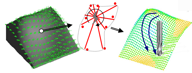
CAM user. Figure 8.10 shows the proposed new methodology for the implementa-
tion in CAM programming. The user defines a set of control points on the surface,
projecting a grid. The finer the grid, the greater the amount of information about
cutting forces that can be collected. At each surface point, the excess of material to
be machined (theoretically the depth of cut a
p
) is calculated from the CAM output
file of the previous semi-finishing operation. With this input data, the cutting
forces prediction model presented in Section 8.4.1 is applied. Cutting force com-
ponents are obtained each 15° (24 directions at each control point) for both down-
milling and upmilling cases. Two options can be followed at this step:
• Select a global milling direction (zig, zag, or zig-zag) that minimises the
mean value of the deflection force. This leads to simple linear tool paths
that are easily programmed.
• Define tool paths specially adapted to the minimum force direction at each
control point, performing a milling process with tool paths winding on the
part surface. CAM programming is supported by the guidelines obtained
from the linkage of all the minimum deflection force directions at each of
all the control points. Sometimes, this approach can result in complex tool
paths that can produce poor roughness results or time-intensive operations;
therefore, this method should be applied with these other considerations in
mind to achieve a high-quality surface and good machining time.
Figure 8.10. Integration of cutting force into three-axis CAM. (A) Selection of control
points; (B) estimation along each 15°, upmilling in this case. (C) Selection of the minimum
force tool path
C. Definition of the minimum
deflection tool paths
A. Selection of control points
29
12
23
31
24
26
11
25.5
B. Evaluation of cutting
force each 15º