Davim J. Paulo (editor). Machining. Fundamentals and Recent Advances
Подождите немного. Документ загружается.

200 V.P. Astakhov
3. Meticulous management of MWF. Although this aspect appears to have
the greatest impact on the ecological, health and cost aspect of MWFs, it is
still the most neglected one. The objective of MWF management is two-
fold: firstly to extend MWF life as much as possible and secondly to dis-
pose of unusable MWFs at the lowest cost. An MWF management plan
normally includes: continuously removing metal chips and tramp oil; thor-
ough cleaning of the MWFs system according to the preventive manage-
ment (PM) schedule; pumping MWFs from the sump; removing all metal
chips and fines; cleaning any oily residues that remain on any surface; fill-
ing the sump with a good cleaner using clean water and circulating the
cleaner through the coolant system for several hours; application of a
cleaning solution to machine surfaces that are not contacted by the MWF
during machine operation; pumping cleaning solution from the sump; wip-
ing cleaning solution residues from the sump; rinsing the entire coolant
system with clean water; rinsing the system again if necessary to remove
all residues; and recharging the system with reclaimed or new coolant im-
mediately to protect metal surfaces against corrosion. Skerlos discussed the
realization of particular steps in this plan with modern equipment [18].
4. Gradual reduction of MWF usage by increasing the use of near-dry and
dry machining. At present, many efforts are being undertaken to develop
advanced machining processes using less or no MWFs. Machining without
the use of MWFs has become a popular avenue for eliminating the prob-
lems associated with the MWF management [10].
Dry machining has its advantages and associated drawbacks. The advantages of
dry machining are obvious: cleaner parts, no waste generation, reduced cost of
machining, reduced cost of chip recycling (no residual oil), etc. However, these
advantages do come at a cost. The most prohibitive part of switching to dry
machining is the large capital expenditure required to start a dry machining op-
eration. Machines and tools designed for MWFs cannot be readily adapted for
dry cutting [10].
New, more powerful machines must be purchased, and special tooling is often
needed to withstand the high temperatures generated in dry cutting. The quality of
machined parts may be affected significantly as the properties of the machined
surface are significantly altered by dry machining in terms of its metallurgical
properties and residual machining stresses. High cutting forces and temperatures
in dry machining may cause the distortion of parts during machining. Moreover,
parts are often rather hot after dry machining so their handling, inspection gaug-
ing, etc., may present a number of problems.
Near-dry machining (NDM) formerly known as minimum quantity lubrication
(MQL) machining, was developed to provide at least partial solutions to the listed
problems with dry machining. This following sections aim to present some impor-
tant aspects of NDM.
Ecological Machining: Near-dry Machining 201
7.5 Nearly Dry Machining (NDM)
7.5.1 How NDM Operates
General speaking, near-dry machining (NDM), also known as minimal quantity
lubrication (MQL) machining, supplies very small quantities of lubricant to the
machining zone. It was developed as an alternative to flood and internal high-
pressure coolant supply to reduce MWFs consumption.
In NDM, the cooling media is supplied as a mixture of air and an oil in the
form of an aerosol (often referred to as the mist). An aerosol is a gaseous suspen-
sion (hanging) into air of solid or liquid particles. In NDM, aerosols are oil drop-
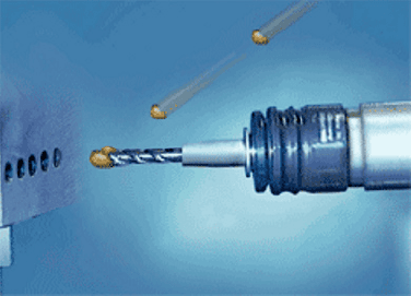
lets dispersed in a jet of air. An idealized picture of NDM is shown in Figure 7.1:
small oil droplets carried by the air fly directly to the tool working zone, providing
the needed cooling and lubricating actions.
Aerosols are generated using a process called atomization, which is the conver-
sion of bulk liquid into a spray or mist (i.e., collection of tiny droplets), often by
passing the liquid through a nozzle. An atomizer is an atomization apparatus;
carburetors, airbrushes, misters, and spray bottles are only a few examples of the
atomizers used ubiquitously. In internal combustion engines, fine-grained fuel
atomization is instrumental to efficient combustion. Despite the name, it does not
usually imply that the particles are reduced to atomic sizes. Rather, droplets of
1–5 μm are generated. Because MWF cannot be seen in the working zone, and
because the chips look and feel dry, this application of minimum-quantity lubri-
cant is called near-dry machining.
An atomizer is an ejector in which the energy of compressed gas, usually air
taken from the plant supply, is used to atomize oil. Oil is then conveyed by the air
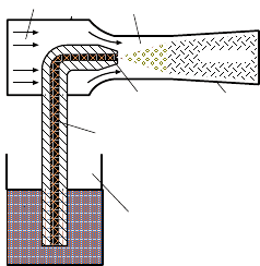
in a low-pressure distribution system to the machining zone. The principle of the
atomizer is shown in Figure 7.2. As the compressed air flows through the Venturi
path, the narrow throat around the discharge nozzle creates a Venturi effect in the
mixing chamber, i.e., a zone where the static pressure is below the atmospheric
pressure (often referred to as a partial vacuum) [19,
20]. This partial vacuum
draws the oil up from the oil reservoir where the oil is maintained under a constant
Figure 7.1. Idealized image of NDM
202 V.P. Astakhov
hydraulic head. The air rushing through the mixing chamber atomizes the oil
stream into an aerosol of micron-sized particles.
The design of the atomizer is critical in NDM as it determines the concentration
of the aerosol and the size of droplets. Unfortunately, this is one of the most ne-
glected aspect in casual application of NDM. Several machine tool companies
have patented their designs (for example, US patents 6 923 604 and 6 602 031). In
such designs, the position of the discharge nozzle is controlled by the machine
controller so the parameters of the aerosol are changed depending upon the ma-
chining conditions.
7.5.2 Classification of NDM
Unfortunately, there is no accepted classifications of NDM so it is very difficult
for a practical engineer or plant manager to make the proper choice about the
regimes of NDM and equipment needed.
7.5.2.1 Classification by Aerosol Supply
The first level of NDM classification includes a way by which aerosol is supplied
into the machining zone:
1. NDM 1: NDM with external aerosol supply. In NDM 1, the aerosol is sup-
plied by an external nozzle placed in the machine similar to a nozzle for
flood MWF supply.
2. NDM 2: NDM with internal (through-tool) aerosol supply. In NDM 2, the
aerosol is supplied through the tool similar to the high-pressure method of
internal MWFs supply.
As the name implies, NDM with an external aerosol supply (NDM 1) includes the
external nozzle that supplies the aerosol. There are two options in NDM 1, which
are shown in Figure 7.3:
1.1. NDM 1 with an ejector nozzle. The oil and the compressed air are supplied
to the ejector nozzle and the aerosol is formed just after the nozzle, as
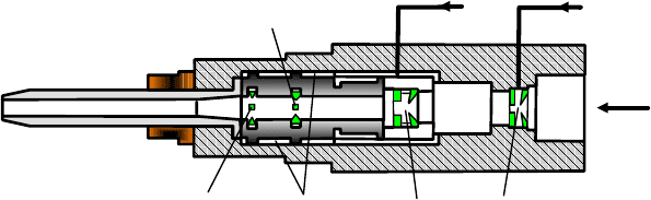
shown in Figure 7.3. One of the possible designs of ejector nozzle is shown
in Figure 7.4. As can be seen, it has two air passages. The first one is ex-
Mixing chamber
Diffuser
Oil lift tube
Oil reservoir
Nozlze
Aerosol
Comp
r
essed ai
r
Figure 7.2. Model of a simple atomizer
Ecological Machining: Near-dry Machining 203
ternal and creates the air envelope that served as the mixing chamber. The
second one provides the atomizing air supply. The oil to be atomized is
supplied through the central passage.
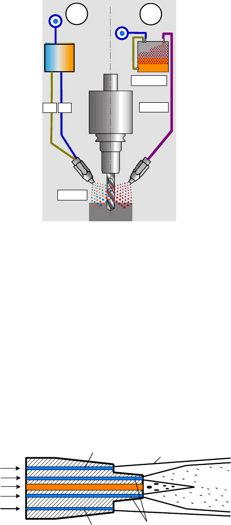
1.2. NDM 1 with a conventional nozzle. The aerosol is prepared in an external
atomizer and then supplied to a conventional nozzle, as shown in Fig-
ure 7.3. The nozzle deign is similar to that used in flood MWF supply.
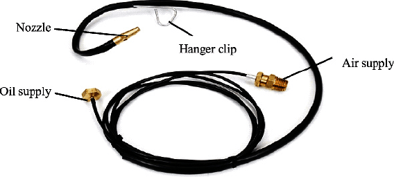
NDM 1.1 is probably the cheapest and simplest method. For example, the Spra-
Kool Midget unit shown in Figure 7.5 is advertised as an economical method of
applying an MWF spray for machining. The Spra-Kool unit works on an air pres-
sure of 0.2–1.0 MPa, which should be adjusted on the compressor. Attaching the
ball-check fitting to the air supply, dropping the suction tube into an oil container,
and locating the nozzle by means of the spring-wire attaching clip, one can get
NDM for a cost of US $30. The soft wire in the nose can be bent to direct the
spray to the work. It is designed for easy transfer from one machine to another.
1
2
Aerosol
Aerosol
Oil
Air
Atomizer
Figure 7.3. The principles of NDM 1.1 and NDM 1.2
Oil
Air
Air
Droplets
15-40
μ
m
Outside air nozzles
Air envelope to form a
mixing chamber
Outside air nozzles
I
nside atomizing
air nozzle
Figure 7.4. Nozzle design for NDM 1.1
204 V.P. Astakhov
In reality, however, adjustments are not that simple. If no special precautions
are taken, the unit generates a dense mist that covers everything in the shop,
including the operator’s lungs. To prevent this from happening and to gain the full
control on the parameters of aerosol, one needs to have (design or buy) a hydraulic
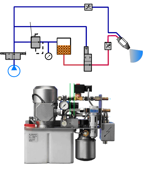
unit similar to that shown in Figure 7.6. When such a unit is used, the parameters
of the aerosol can be adjusted in a wide range in terms of droplet size and oil flow
rate by setting appropriate air and oil flow rates and by adjusting the pressure in
the oil reservoir. Moreover, such a device prevents oil spills as it shuts down the
oil supply line when the air supply is not available.
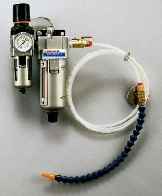
NDM 1.2 is probably the simplest method. An external atomizer required is an
off-the-shelf product, such as that shown in Figure 7.7. As can be seen, the same
nozzle as is used for flood MWF is used, so that NDM 1.2 can be used with the
same sets of nozzles installed in the machine.
NDM 1 has the following advantages:
• Inexpensive and simple retrofitting of the existing machines
• The same cutting tools used for flood MWF will work
• Easy to use and maintain equipment
• The equipment can be moved from one machine to another
• Relative flexibility of NDM 1.2 as the position of nozzle can be adjusted
for the convenience of operator. As such, the parameters of the aerosol do
not depend on the particular nozzle location.
• The equipment can be moved from one machine to another.
• Various standard and special nozzle designs are available with NDM 1.2 to
suite most common metal machining operations and tool designs. It is
proven to be particularly effective in face milling and sawing
NDM 1 has the following disadvantages:
• Both NDM 1.1 and 1.2 do not work well with drills and boring tools as an
aerosol cannot penetrate into the hole being machined
• A critical aspect for NDM 1.1 and an important aspect for NDM 1.2 is the
location of the nozzle relative to the working part of the tool. For both
Figure 7.5. Spra-Kool Midget
Ecological Machining: Near-dry Machining 205
Air flow rate regulator
Oil shut down valve
Ejector
nozzle
Oil flow
rate
regulator
Oil reservoir
Manometer
Directional
control
valve
Compressor
Pressure
reducing valve
methods, this location must be fixed, i.e., should not change as the tool
moves. Note that this issue is not that important in flood MWF supply
where gravity and the energy of MWF flow cover a much wider range of
possible nozzle locations
• The parameters of the aerosol should be adjusted for each particular metal
machining operation and the work material. This makes NDM 1 less attrac-
tive option in a job-shop environment
As the name implies, NDM with internal aerosol supply (NDM 2) includes inter-
nal passages for aerosol supply. There are two options in NDM 2: NDM 2.1 with
an external atomizer as shown in Figure 7.8 and NDM 2.2 with an internal atom-
izer located in the spindle of the machine as shown in Figure 7.9.
In NDM 2.1, the aerosol is prepared in an external atomizer and then supplied
trough the spindle and the internal channels made in the tool. When NDM 2.1 is
used on machining centres or manufacturing cells, the aerosol supply unit has to
react to the frequent tool changes that nowadays take only 1 or 2 s, setting the
proper aerosol parameters for each given tool/operation. If the aerosol unit is shut
down every time a tool change takes place then it requires some time to fill the
whole system with aerosol again. VOGER, a NDM equipment suppler, has devel-
oped the bypass principle illustrated in Figure 7.8. The aerosol is produced con-
Figure 7.6. Aerosol control unit
206 V.P. Astakhov
tinuously and supplied to the directional control valve, which allows aerosol into
the spindle as soon as a tool change is over.
NDM 2.1 has the following advantages:
• Lowest initial cost
• The possibility of keeping two cooling system on the machine: flood and
NDM
• Relatively simple installation and control
• Accurate control of the aerosol parameters so that they can be easily ad-
justed by the machine controller for a given tool or even operation with the
same tool
NDM 2.1 has the following drawbacks:
• Spindle rotation creates a centrifugal force field that coats the wall of the
aerosol delivery channel with oil that must be removed periodically. For
a high-volume production manufacturing factory (plant, shop, line, cell),
this downtime may be intolerable and costly. This additional cost can eas-
ily offset the savings on NDM.
• Special care should be taken of the position of the flexible line that con-
nects the external aerosol unit with the spindle. Firstly, it should be as
close to the machine as possible. Secondly, the radius of curvature of this
line should not be less that 200 mm to prevent aerosol decomposition.
• The parameters of the aerosol that enters the machining zone can be differ-
ent than those controlled in the outside unit depending upon the spindle
speed and the conditions of the supply channels.
LENOX
®
MICRONIZERS
Figure 7.7. Accessories with the external atomizer by Lenox Co. for NDM 1.2
Ecological Machining: Near-dry Machining 207
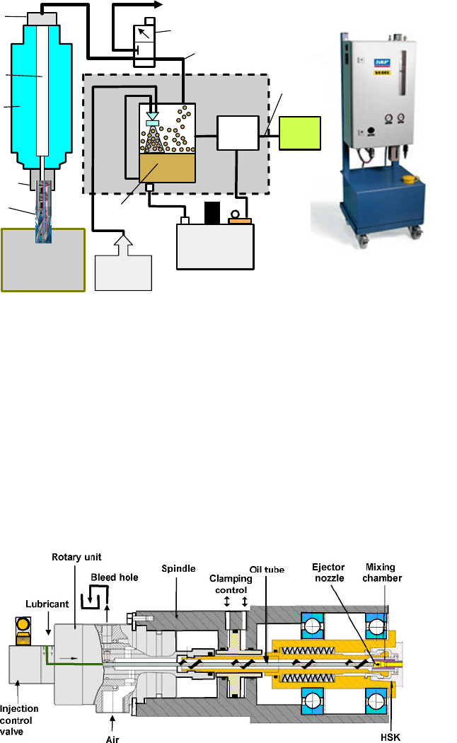
Generally, NDM 2.2 is a more attractive concept: to mix the air and oil as close
as possible to the tool in a well-designed mixing chamber. To do this, the oil is
supplied through the spindle through a central tube within the surrounding annular
air duct (Figure 7.9). The air and oil are mixed in the mixing chamber close to the
tool. Because the air–oil aerosol is influenced only by the spindle rotation for
a short distance, the discharge response from the tool tip is said to be improved.
As discussed above, the design of the mixing chamber and ejector nozzle as well
as the controlling of the oil discharge are critical for the application, and is nor-
mally patented by the machine tool manufactures.
Figure 7.8. Principle of NDM 2.1 and the LubriLean DigitalSuper1 (Vogel)
Figure 7.9. Principle of NDM 2.2
Workpiece
Internal
control
system
SPC
Machine
tool
Filling
system
Tool with
internal
channels
Aerosol
line
Data line
Aerosol
preparation and
control system
Directional control valve
Machine exhaust
Rotary
unit
Spindle
Tool holder
Compressed
air supply
Atomizer
Aerosol
channel
208 V.P. Astakhov
In implementing this NDM 2.2 approach, two important issues need to be ad-
dressed:
• Two nested rotary couplings must be provided for the air and oil connec-
tions, which raises questions regarding reliability and durability.
• The system plumbing must be prevented from shifting and changing the
spindle’s residual unbalance.
As the spindle speeds increase, both of these design issues become more of a prob-
lem. Moreover, to gain maximum advantage of NDM 2.2, a special computer-
controlled solenoid must be installed on the machine to adjust the parameters of
the aerosol for each particular tool/operation. All of these factors make retrofitting
of an existing machine with NDM 2.2 rather cumbersome and the economic gain
becomes uncertain.
7.5.2.2 Classification by Aerosol Composition
In the simplest cases of NDM 1 and 2, the aerosol is an air–oil mixture. The dis-
charge of the oil in this mixture is selected to be in the range 30–600 ml/h depend-
ing upon the design of the NDM system, the nature of the machining operation,
the work material and many other factors. Unfortunately, not many recommenda-
tions of the mixture composition are available. Advanced NDM (ANDM) uses
aerosol that includes not only oil but also some other components. This Section
considers two examples of ANDM: oil on water droplet (OoW NDM) and ad-
vanced minimum quantity cooling lubrication NDM (AMQCL NDM).
OoW NDM includes the supply of water droplets covered with a thin oil film
[21–23]. As claimed by its authors, this method possesses both great cooling and
lubricating abilities. The former is due to water properties (high specific heat
capacity, density and thermal conductivity compared to air) and its evaporation.
The latter is due to the specific droplet configuration.
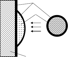
The concept of OoW NDM is shown in Figure 7.10, which shows an ideal
OoW droplet moving towards a hot surface. When the droplet reaches the tool or
hot workpiece surface, the lubricant oil spreads over the surface in advance of
water spreading. The water droplets are expected to perform three tasks: carrying
the lubricant, spreading the lubricant effectively over the surface due to inertia and
Droplet
Oil film
Water
Workpiece
Figure 7.10. The concept of the oil-on-water NDM (NDM 3)
Ecological Machining: Near-dry Machining 209
cooling the surface due to its high specific heat and evaporation. To make this
concept practical, i.e., to generate OoW droplets, a specially designed discharge
nozzle is needed.
Figure 7.12 presents one of the designs [23] that, according to its authors, pro-
vides reliable continues supply of oil-on-water droplets in a controlled fashion.
Rated by the flow meter, compressed air is fed through the central channel of the
nozzle. Another air flow goes into the control unit where it is mixed by the control
valve with oil in a known measurable proportion. Then the resulting mixture is fed
into the first array of the ejector nozzles, through which the mixture is ejected and
atomized by the main air flow. Water is supplied through a flow meters to the
second arrays of the ejector nozzles as shown in Figure 7.11. Passing through
these nozzles, the water is also atomized. According to the authors, when two
atomized flows meet after the second nozzles, adhesion of oil to the surface of
water droplets takes place as the average size of water droplets is greater than that
of the oil droplets due to the difference between the surface tensions of water and
oil. Selecting a particular oil that has favorable spreading properties over a water
surface, one can achieve automatic generation of OoW droplets. So far, all known
OoW nozzles work using this principle. However, the nozzle shown in Figure 7.11
is designed with third and fourths array of ejector nozzle to increase opportunities
for the collision of water and oil particles to form OoW particles. This allows an
increase of the feasible range of oil-to-water ratios. Moreover, these additional
nozzles prevent oil particles from agglomerating and accumulation inside the
mixing chamber and the discharge nozzle.
The size of OoW droplets when they hit the surface of the workpiece or tool is
about 100–200 μm, which is much greater than that with the aforementioned tradi-
tional NDM approaches. This is considered a plausible explanation for the lower
cutting forces in aluminium machining compared to traditional NDM with oil
aerosol or even to the usual MWF flood machining. Improvements in surface
finish and tool life with this method are also reported.
The advanced minimum quantity cooling lubrication (AMQCL) approach and the
corresponding system developed by CoolTool Co. (Eagan, MN; Valencia, CA, USA)
combines a source of propellant gas (i.e., compressed air), lubrication additives
(i.e., soy oil) and solid and/or gaseous CO
2
(i.e., coolant) in various concentrations
to form a widely adjustable aerosol. A schematic of the AMQLC method is shown
Bypass
4th nozzle
Water
Air
Oil and air
2nd nozzle
1st nozzle
3rd nozzle
Figure 7.11. One of the developed nozzles for aerosol containing air, oil and water