Coburn J.W. Algebra and Trigonometry
Подождите немного. Документ загружается.

750
750 CHAPTER 7 Applications of Trigonometry 7-40
EXTENDING THE CONCEPT
For the arbitrary vectors and
and the scalars c and k, prove the following
vector properties using the properties of real numbers.
89. 90.
91.
92.
93.
94. 95.
96. 97.
98. Consider an airplane flying at 200 mph at a
heading of Compute the groundspeed of the
plane under the following conditions. A strong,
40-mph wind is blowing (a) in the same direction;
(b) in the direction of due north ( ); (c) in the
direction heading (d) in the direction heading
and (e) in the direction heading What
did you notice about the groundspeed for (a) and
(b)? Explain why the plane’s speed is greater than
200 mph for (a) and (b), but less than 200 mph for
the others.
225°.270°;
315°;
0°
45°.
1c k2u cu kuk1u v2 ku kv
u 1u2 0u 0 u
1ck2u c1ku2 k1cu2
1u v2 w u 1v w2
u v u 1v2
0u 0 k01u u
w He, fI
u Ha, bI, v Hc, dI,
99. Show that the sum of the vectors given, which form
the sides of a closed polygon, is the zero vector.
Assume all vectors have integer coordinates and
each tick mark is 1 unit.
100. Verify that for and
(Hint: Create the vector and find its magnitude.)
101. Referring to Exercises 87 and 88, suppose the
dentist needed the pivot joint at the light (the
furthest joint from the wall) to be at (80, 20) for a
certain patient or procedure. Find at least one set of
“joint angles” that will make this possible.
u
v
v
v
2a
2
b
2
,
v
v
1.
v ai bj
x
y
u
t
s
r
p
v
85. Headings and cross-winds: An airplane is flying
at 250 mph on a heading of There is a strong,
35 mph wind blowing from the southwest on a
heading of What is the true course and speed
of the plane (relative to the ground)?
10°.
75°.
86. Headings and currents: A cruise ship is traveling at
16 knots on a heading of There is a strong water
current flowing at 6 knots from the northwest on a
heading of What is the true course and speed of
the cruise ship?
120°.
300°.
College Algebra & Trignometry—
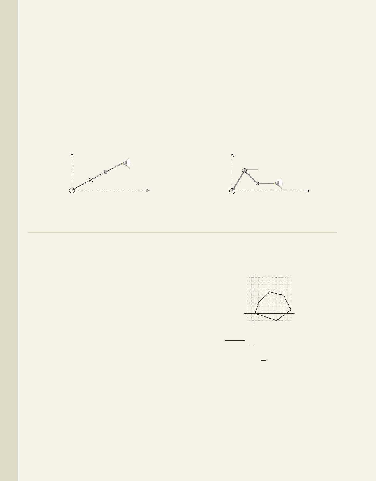
The lights used in a dentist’s office are multijointed so they can be configured in multiple ways to accommodate
various needs. As a simple model, consider such a light that has the three joints, as illustrated. The first segment has
a length of 45 cm, the second is 40 cm in length, and the third is 35 cm.
87. If the joints of the light are positioned so a straight
line is formed and the angle made with the
horizontal is determine the approximate
coordinates of the joint nearest the light.
15
15°,
88. If the first segment is rotated above horizontal,
the second segment (below the horizontal),
and the third segment is parallel to the horizontal,
determine the approximate coordinates of the joint
nearest the light.
75
30
30°
75°
cob19529_ch07_736-752.qxd 12/27/08 16:01 Page 750
751
7-41 Reinforcing Basic Concepts 751
102. (6.1) Derive the other two common versions of the
Pythagorean identities, given
103. (2.5) Evaluate each expression for (if possible):
a. b.
c. y
A
1
3
x 5
y
5
x 3
y ln12x 72
x 3
sin
2
x cos
2
x 1.
104. (6.5) Evaluate the expression by
drawing a representative triangle.
105. (3.4) Graph the function and find
its zeroes.
g1x2 x
3
7x
cscctan
1
a
55
48
bd
MAINTAINING YOUR SKILLS
1. Beginning with solve for sin B.
2. Given solve for cos B.
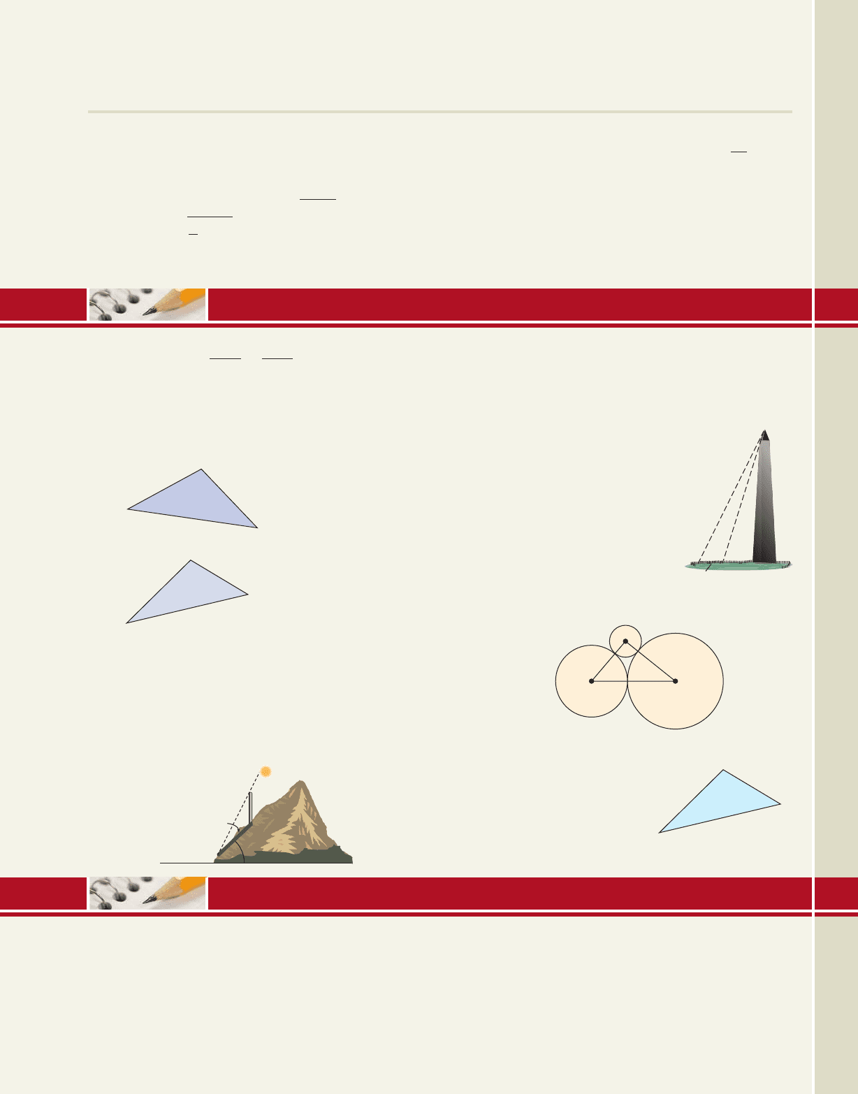
Solve the triangles shown below using any appropriate
method.
3.
4.
Solve the triangles described below using the law of
sines. If more than one triangle exists, solve both.
5.
6.
7. A large highway sign is erected on a steep hillside
that is inclined from the horizontal. At 9:00
A.M.45°
C 27°, a 70 yd, c 100 yd
A 44°, a 2.1 km, c 2.8 km
A
B
C
25 cm
21 cm
17 cm
B
C
A
250 m
207 m
31
b
2
a
2
c
2
2ac cos B,
sin A
a
sin B
b
,
the sign casts a 75 ft shadow. Find the height of the
sign if the angle of elevation (measured from a
horizontal line) from the tip of the shadow to the top
of the sign is .
8. Modeled after an Egyptian
obelisk, the Washington
Monument (Washington, D.C.)
is one of the tallest masonry
buildings in the world. Find the
height of the monument given
the measurements shown (see
the figure).
9. The circles shown here have
radii of 4 cm, 9 cm, and 12 cm,
and are tangent to each other. Find the angles formed
by the line segments joining their centers.
10. On her delivery route, Judy
drives 23 miles to
Columbus, then 17 mi to
Drake, then back home to
Balboa. Use the diagram
given to find the distance
from Drake to Balboa.
65°
58
7
0
44 m
Scaled Drawings and the Laws of Sine
and Cosine
In mathematics, there are few things as satisfying as the
tactile verification of a concept or computation. In this
Reinforcing Basic Concepts, we’ll use scaled drawings to
verify the relationships stated by the law of sines and the
law of cosines. First, gather a blank sheet of paper, a ruler
marked in centimeters/millimeters, and a protractor. When
working with scale models, always measure and mark as
carefully as possible. The greater the care, the better the
C
D
B
23 mi
17 mi
21
75 ft
45
MID-CHAPTER CHECK
REINFORCING BASIC CONCEPTS
College Algebra & Trignometry—
cob19529_ch07_736-752.qxd 11/19/08 2:27 AM Page 751 epg HD 049:Desktop Folder:Satya 18/11/08:
752 CHAPTER 7 Applications of Trigonometry 7-42
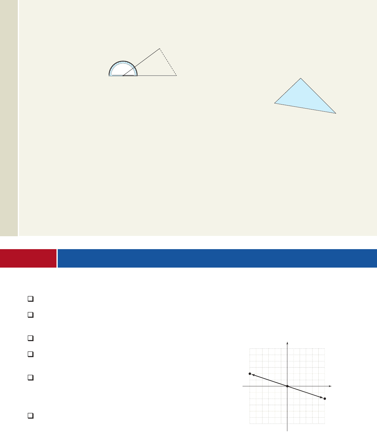
substitute known
values
results. For the first illustra-
tion (see Figure 7.54), we’ll
draw a 20-cm horizontal line
segment near the bottom of
the paper, then use the left
endpoint to mark off a
angle. Draw the second side a length of 18 cm. Our first
goal is to compute the length of the side needed to com-
plete the triangle, then verify our computation by mea-
surement. Since the current “triangle” is SAS, we use the
law of cosines. Label the as the top vertex as
and the right endpoint as
law of cosines with respect to a
simplify (round to 10)
combine terms
solve for a
The computed length of side a is 11.6 cm, and if you
took great care in drawing your diagram, you’ll find the
missing side is indeed very close to this length.
Exercise 1: Finish solving the triangle above using the
law of sines. Once you’ve computed and C,B
a 11.6
134.2
724 589.8
1202
2
1182
2
212021182cos 35
a
2
b
2
c
2
2bc cos A
C.
B,A,35°
35°
measure these angles from the diagram using your
protractor. How close was the computed measure to the
actual measure?
For the second illustra-
tion (see Figure 7.55), draw
any arbitrary triangle on a
separate blank sheet, noting
that the larger the triangle,
the easier it is to measure the
angles. After you’ve drawn
it, measure the length of
each side to the nearest millimeter (our triangle turned out
to be ). Now use the law of
cosines to find one angle, then the law of sines to solve the
triangle. The computations for our triangle gave angles of
and What angles did your computa-
tions give? Finally, use your protractor to measure the
angles of the triangle you drew. With careful drawings, the
measured results are often remarkably accurate!
Exercise 2: Using sides of 18 cm and 15 cm, draw a
angle, a angle, and a angle, then complete each
triangle by connecting the endpoints. Use the law of
cosines to compute the length of this third side, then
actually measure each one. Was the actual length close to
the computed length?
70°50°
35°
38.7°.45.9°,95.4°,
21.2 cm 13.3 cm 15.3 cm
Figure 7.55
Figure 7.54
20 cm
18 cm
?
90
35
180 0
13.3 cm
15.3 cm
21.2 cm
In Section 7.3 we introduced the concept of a vector, with its geometric, graphical, and
algebraic representations. We also looked at operations on vectors and employed vector
diagrams to solve basic applications. In this section we introduce additional ideas that
enable us to solve a variety of new applications, while laying a strong foundation for
future studies.
A. Vectors and Equilibrium
Much like the intuitive meaning of the word,
vector forces are in equilibrium when they
“counterbalance” each other. The simplest
example is two vector forces of equal mag-
nitude acting on the same point but in oppo-
site directions. Similar to a tug-of-war with
both sides equally matched, no one wins. If
vector F
1
has a magnitude of 500 lb in the
positive direction, would need
vector to counter it. If the
forces are nonquadrantal, we intuitively
sense the components must still sum to zero,
and that would need
for equilibrium to occur
(see Figure 7.56). In other words, two
vectors are in equilibrium when their sum is
F
4
H600, 200I
F
3
H600, 200I
F
2
H500, 0I
F
1
H500, 0I
Learning Objectives
In Section 7.4 you will learn how to:
A. Use vectors to investi-
gate forces in equilibrium
B. Find the components of
one vector along
another
C. Solve applications
involving work
D. Compute dot products
and the angle between
two vectors
E. Find the projection of
one vector along
another and resolve a
vector into orthogonal
components
F. Use vectors to develop
an equation for nonverti-
cal projectile motion,
and solve related
applications
7.4 Vector Applications and the Dot Product
x
y
H
600, 200I
H600, 200I
F
3
F
4
H600, 200I H600, 200I
H
0, 0
I
0
F
3
F
4
Figure 7.56
College Algebra & Trignometry—
cob19529_ch07_736-752.qxd 12/30/08 3:32PM Page 752 User-S200 Data Disk:broker:MH-DUBUQUE:MHDQ092:MHDQ092-7.3:
x
y
64
18
P
6.3
4.5
H4.0, 5.9I
F
2
F
1
5
55
5
College Algebra & Trignometry—
7-43
Section 7.4 Vector Applications and the Dot Product 753
the zero vector 0. If the forces have unequal magnitudes or do not pull in opposite
directions, recall a resultant vector can be found that represents the com-
bined force. Equilibrium will then occur by adding the vector (F) and this vector
is sometimes called the equilibriant.
These ideas can be extended to include any number of vector forces acting on the
same point. In general, we have the following:
Vectors and Equilibrium
Given vectors acting on a point P,
1. The resultant vector is
2. Equilibrium for these forces requires the vector where
EXAMPLE 1
Finding the Equilibriant for Vector Forces
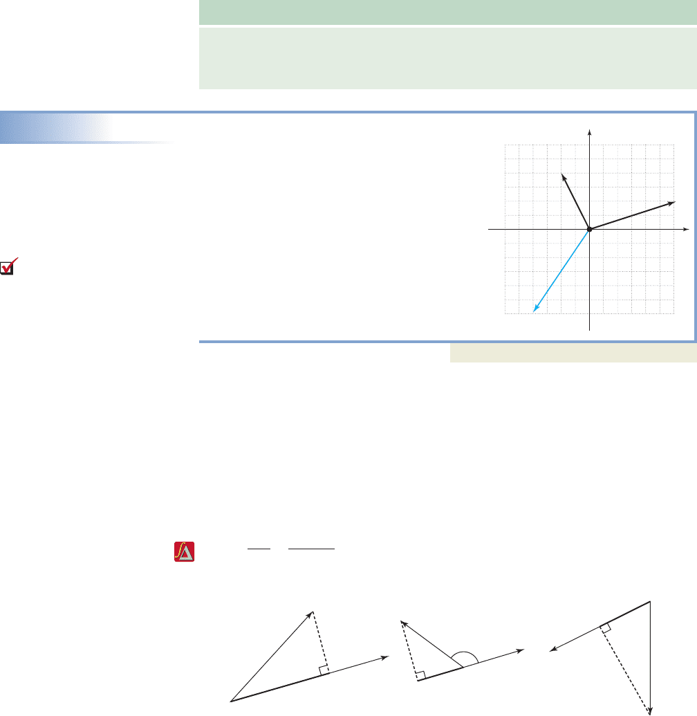
Two force vectors F
1
and F
2
act on the point
P as shown. Find a force F
3
so equilibrium
will occur, and sketch it on the grid.
Solution
Begin by finding the horizontal and vertical
components of each vector. For F
1
we have
and for F
2
we have
The resultant vector is
meaning
equilibrium will occur by applying
the force (see figure).
Now try Exercises 7 through 20
B. The Component of u along v: comp
v
u
As in Example 1, many simple applications involve position vectors where the angle
and horizontal/vertical components are known or can easily be found. In these situa-
tions, the components are often quadrantal, that is, they lie along the x- and y-axes
and meet at a right angle. Many other applications require us to find components of
a vector that are nonquadrantal, with one of the components parallel to, or lying along
a second vector. Given vectors u and v, as shown in Figure 7.57, we symbolize the
component of u that lies along v as comp
v
u, noting its value is simply since
As the diagrams further indicate, regardless comp
v
u
u
cos cos
adj
hyp
comp
v
u
u
.
u
cos
1F H4.0, 5.9I
F F
1
F
2
H4.0, 5.9I,
H6.0, 1.9I.
H6.3 cos 18°, 6.3 sin 18°I
H4.5 cos 64°, 4.5 sin 64°I H2.0, 4.0I,
F 112F 01F,
F F
1
F
2
###
F
n
.
F
1
, F
2
, . . . , F
n
1
F F
a
F
b
comp
v
u
comp
v
u
comp
v
u
u
u
u
0 q q
u
u
u
v
v
v
of how the vectors are oriented. Note that even when the components of a vector do
not lie along the x- or y-axes, they are still orthogonal (meet at a angle).
It is important to note that comp u is a scalar quantity (not a vector), giving only
the magnitude of this component (the vector projection of u along v is studied later
in this section). From these developments we make the following observations regard-
ing the angle at which vectors u and v meet:
v
90°
Figure 7.57
A. You’ve just learned how
to use vectors to investigate
forces in equilibrium
cob19529_ch07_753-765.qxd 11/19/08 2:31 AM Page 753 epg HD 049:Desktop Folder:Satya 18/11/08:
754 CHAPTER 7 Applications of Trigonometry 7-44
p
G
v
850 lb
␣

p
G
v
850 lb
␣

Figure 7.58 Figure 7.59
comp
v
G
G
850
lb
v
65
Vectors and the Component of u Along v
Given vectors u and v, which meet at an angle ,
1.
2. If if
3. If u and v have the same direction and
4. If u and v are orthogonal and
5. If u and v have opposite directions and
EXAMPLE 2
Finding the Component of Vector G Along Vector v
Given the vectors G and v with lb as shown in
the figure, find comp
v
G.
Solution
Using we have lb.
The component of G along v is about 359 pounds.
Now try Exercises 21 through 26
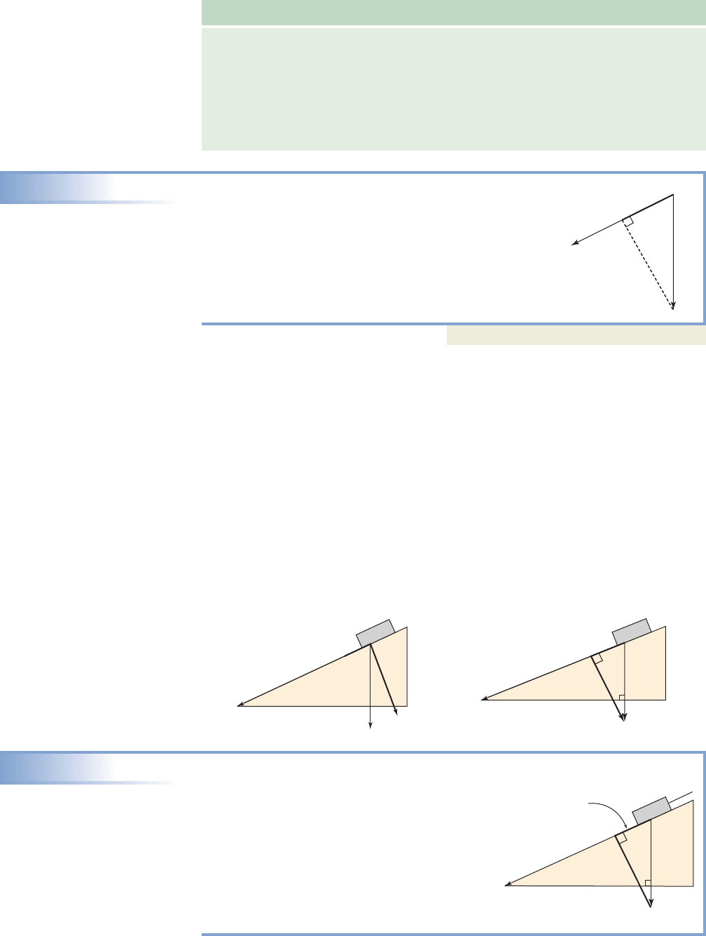
One interesting application of equilibrium and comp
v
u involves the force of
gravity acting on an object placed on a ramp or an inclined plane. The greater the
incline, the greater the tendency of the object to slide down the plane (for this study,
we assume there is no friction between the object and the plane). While the force of
gravity continues to pull straight downward (represented by the vector G in
Figure 7.58), G is now the resultant of a force acting parallel to the plane along vector
v(causing the object to slide) and a force acting perpendicular to the plane along vector
p (causing the object to press against the plane). If we knew the component of G along
v (indicated by the shorter, bold segment), we would know the force required to keep
the object stationary as the two forces must be opposites. Note that G forms a right
angle with the base of the inclined plane (see Figure 7.59), meaning that and must
be complementary angles. Also note that since the location of a vector is unimportant,
vector p has been repositioned for clarity.
850 cos 65° 359
G
cos comp
v
G
G
850
comp
v
u
u
. 180°,
comp
v
u 0. 90°,
comp
v
u
u
. 0,
90° 6 6 180°, comp
v
u 6 0.0 6 6 90°, comp
v
u 7 0;
comp
v
u
u
cos .
EXAMPLE 3A
Finding Components of Force for an Object on a Ramp
A 850-lb object is sitting on a ramp that is
inclined at . Find the force needed to hold the
object stationary (in equilibrium).
Solution
Given we know This means
the component of G along the inclined plane is
or about 359 lb. A force
of 359 lb is required to keep the object from
sliding down the incline (compare to Example 2).
comp
v
G 850 cos 65°
65°. 25°,
25°
G
v
850 lb
850 lb
comp
v
G
25

College Algebra & Trignometry—
cob19529_ch07_753-765.qxd 11/19/08 2:31 AM Page 754 epg HD 049:Desktop Folder:Satya 18/11/08:
G
v
2000 lb
2000 lb
15

7-45 Section 7.4 Vector Applications and the Dot Product 755
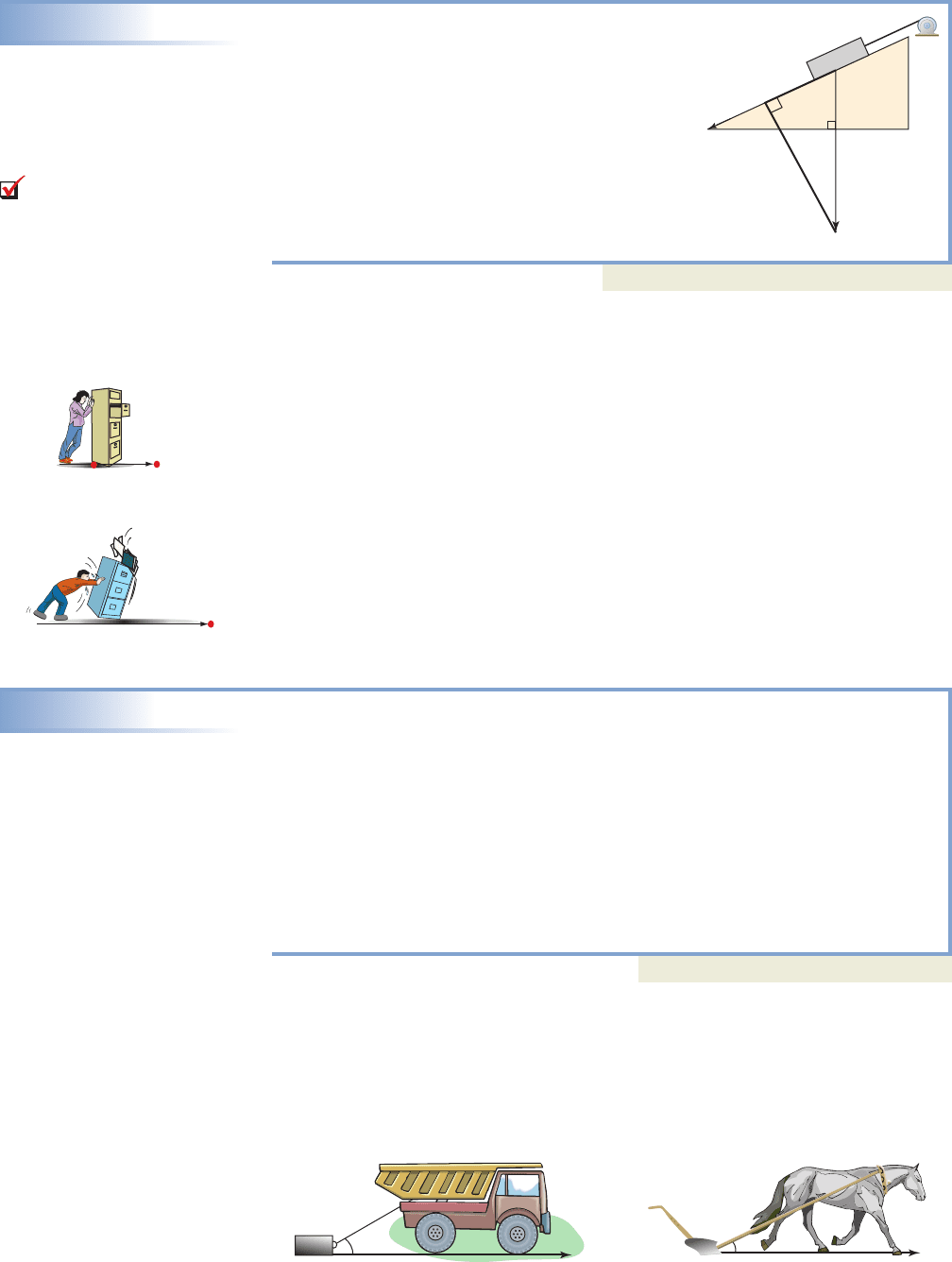
EXAMPLE 3B
A winch is being used to haul a 2000-lb block of
granite up a ramp that is inclined at If the winch
has a maximum tow rating of 500 lb, will it be
successful?
Solution
We again need the component of G along the
inclined plane: lb.
Since the capacity of the winch is exceeded, the
attempt will likely not be successful.
Now try Exercises 27 through 30
C. Vector Applications Involving Work
In common, everyday usage, work is understood to involve the exertion of energy or
force to move an object a certain distance. For example, digging a ditch is hard work
and involves moving dirt (exerting a force) from the trench to the bankside (over a
certain distance). In an office, moving a filing cabinet likewise involves work. If the
filing cabinet is heavier, or the distance it needs to be moved is greater, more work is
required to move it (Figures 7.60 and 7.61).
To determine how much work was done by each person, we need to quantify the
concept. Consider a constant force F, applied to move an object a distance D in the
same direction as the force. In this case, work is defined as the product of the force
applied and the distance the object is moved: Work Force
Distance or
If the force is given in pounds and the distance in feet, the amount of work is meas-
ured in a unit called foot-pounds (ft-lb). If the force is in newtons and the distance in
meters, the amount of work is measured in newton-meters (N-m).
EXAMPLE 4
Solving Applications of Vectors — Work and Force Parallel to the
Direction of Movement
While rearranging the office, Carrie must apply a force of 55.8 N to relocate a
filing cabinet 4.5 m, while Bernard applies a 77.5 N force to move a second cabinet
3.2 m. Who did the most work?
Solution
For Carrie: For Bernard:
N-m N-m
Carrie did N-m more work than Bernard.
Now try Exercises 31 and 32
In many applications of work, the force F is not applied parallel to the direction
of movement, as illustrated in Figures 7.62 and 7.63.
In calculating the amount of work done, the general concept of force
distance
is preserved, but only the component of force in the direction of movement is used. In
251.1 248 3.1
248 251.1
177.5213.22 155.8214.52
W
F
D W
F
D
W
F
D.
comp
v
G 2000 cos 75 518
15°.
B. You’ve just learned how
to find the components of one
vector along another
Figure 7.60
Figure 7.61
D
D
Figure 7.62 Figure 7.63
30°
F
D
25°
F
D
College Algebra & Trignometry—
cob19529_ch07_753-765.qxd 12/30/08 17:25 Page 755
756 CHAPTER 7 Applications of Trigonometry 7-46
terms of the component forces discussed earlier, if F is a constant force applied at angle
to the direction of movement, the amount of work done is the component of force
along D times the distance the object is moved.
Force Vectors and Work W
Given a force F applied in the direction of
movement at the acute angle to an object,
and D the distance it is moved,
D
EXAMPLE 5
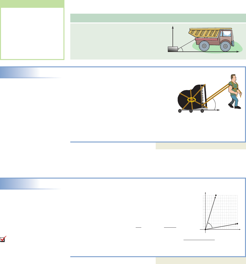
Solving an Application of Vectors—Work and Force
Applied at Angle to the Direction of Movement
To help move heavy pieces of furniture across the
floor, movers sometime employ a body harness
similar to that used for a plow horse. A mover
applies a constant 200-lb force to drag a piano
100 ft down a long hallway and into another room.
If the straps make a angle with the direction of
movement, find the amount of work performed.
Solution
The component of force in the direction of movement is or about 153 lb.
The amount of work done is ft-lb.
Now try Exercises 35 through 40
These ideas can be generalized to include work problems where the component of
force in the direction of motion is along a nonhorizontal vector v. Consider Example 6.
EXAMPLE 6
Solving an Application of Vectors—Forces Along a Nonhorizontal Vector
The force vector moves an object along the
vector as shown. Find the amount of work
required to move the object along the entire length of v.
Assume force is in pounds and distance in feet.
Solution
To begin, we first determine the angle between the vectors.
In this case we have
For (5-12-13 triangle), the component of force in the direction
of motion is With
the work required is or
Now try Exercises 41 through 44
D. Dot Products and the Angle Between Two Vectors
When the component of force in the direction of motion lies along a nonhorizontal
vector (as in Example 6), the work performed can actually be computed more effi-
ciently using an operation called the dot product. For any two vectors u and v, the dot
product is equivalent to
yet is much easier to compute (for the proof
of
see Appendix IV). The operation is defined as follows:
v
,
u
#
v comp
v
u
v
,
comp
v
u
u
#
v
16.52115.572 101.2 ft-lb.
v
W comp
v
F
v
2115.442
2
122
2
15.57,comp
v
F 13 cos 60° 6.5.
F
13
tan
1
a
12
5
b tan
1
a
2
15.44
b 60°.
v H15.44, 2I
F H5, 12I
W 15311002 15,300
200 cos 40°
40°
W
F
cos
Fcos
F
D
40°
D
WORTHY OF NOTE
In the formula
D, observe
that if , we have the old
formula for work when the
force is applied in the
direction of movement
If
and the “effective force” on
the object becomes
F
cos .
cos 1
0,
W FD.
0
W
F
cos
x
y
F
v
H5, 12I
H15.44
, 2
I
60
C. You’ve just learned how
to solve applications involving
work
College Algebra & Trignometry—
cob19529_ch07_753-765.qxd 01/13/2009 08:08 PM Page 756 ssen 1 HD 049:Desktop Folder:Satya 13/01/09:Used file:MHDQ092-7.4:
7-47 Section 7.4 Vector Applications and the Dot Product 757
The Dot Product
Given vectors and In words,
it is the real number found by taking the sum of corresponding component products.
EXAMPLE 7
Using the Dot Product to Determine Force Along a Nonhorizontal Vector
Verify the answer to Example 6 using the dot product
Solution
For and we have giving
The result is 101.2, as in Example 6.
Now try Exercises 45 through 48
Note that dot products can also be used in the simpler case where the direction of
motion is along a horizontal distance (Examples 4 and 5). While the dot product offers
a powerful and efficient way to compute the work performed, it has many other appli-
cations; for example, to find the angle between two vectors. Consider that for any two
vectors u and v,
leading directly to (solve for
).
In summary,
The Angle Between Two Vectors
Given the nonzero vectors u and v:
and
In the special case where u and v are unit vectors, this simplifies to
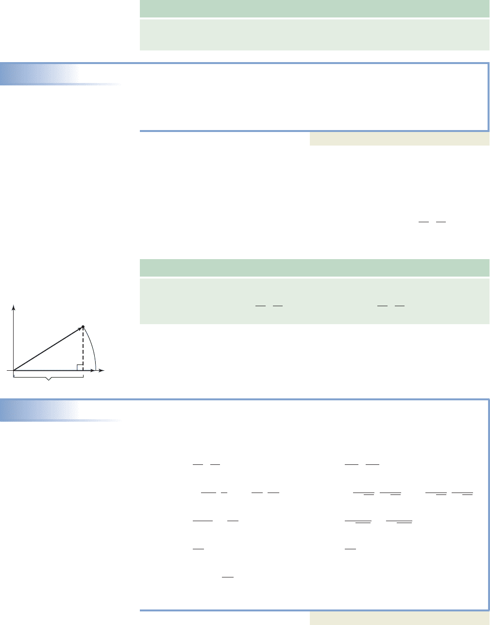
since This relationship is shown in Figure 7.64. The dot product
gives
but and the component of u along v is simply the adjacent
side of a right triangle whose hypotenuse is 1. Hence
EXAMPLE 8
Determining the Angle Between Two Vectors
Find the angle between the vectors given.
a. b.
Solution
a. b.
Now try Exercises 49 through 66
90° 59.5°
cos
1
0 cos
1
a
33
65
b
0
26
0
33
65
12
1676
12
1676
15
65
48
65
h
2
113
,
3
113
i
#
h
6
152
,
4
152
i h
3
5
,
4
5
i
#
h
5
13
,
12
13
i
cos
v
1
v
1
#
v
2
v
2
cos
u
u
#
v
v
v
1
2i 3j; v
2
6i 4ju H3, 4I; v H5, 12I
u
#
v cos .
v
1
v
,
comp
v
u
u
#
v
u
v
1.
cos u
#
v
cos
1
a
u
u
#
v
v
bcos
u
u
#
v
v
cos
cos
u
u
#
v
v
v
,u
#
v
u
cos
5115.442 12122 101.2.
u
#
v H5, 12I
#
H15.44, 2Iv H15.44, 2I,u H5, 12I
u
#
v.
u
#
v Ha, bI
#
Hc, dI ac bd.v Hc, dI,u Ha, bI
u
#
v
Figure 7.64
x
y
(x, y)
comp
v
u x
v
u 1
v 1
College Algebra & Trignometry—
cob19529_ch07_753-765.qxd 12/30/08 17:26 Page 757
758 CHAPTER 7 Applications of Trigonometry 7-48
Note we have implicitly shown that if then u is orthogonal to v. As with
other vector operations, recognizing certain properties of the dot product will enable
us to work with them more efficiently.
Properties of the Dot Product
Given vectors u, v, and w and a constant k,
1. 2.
3. 4.
5. 6.
Property 6 offers an alternative to unit vectors when finding —the dot
product of the vectors can be computed first, and the result divided by the product of
their magnitudes: . Proofs of the first two properties are given here.
Proofs of the others have a similar development (see Exercises 79 through 82). For
any two nonzero vectors and :
Property 1: Property 2:
(since )
Using and
we can also state the follow-
ing relationships, which give us some flexibility on how we approach applications of
the dot product.
For any two vectors and
(1)
standard computation of the dot product
(2) alternative computation of the dot product
(3) replace in (2) with comp
v
u
(4) divide (2) by scalars and
(5) divide (3) by
E. Vector Projections and Orthogonal Components
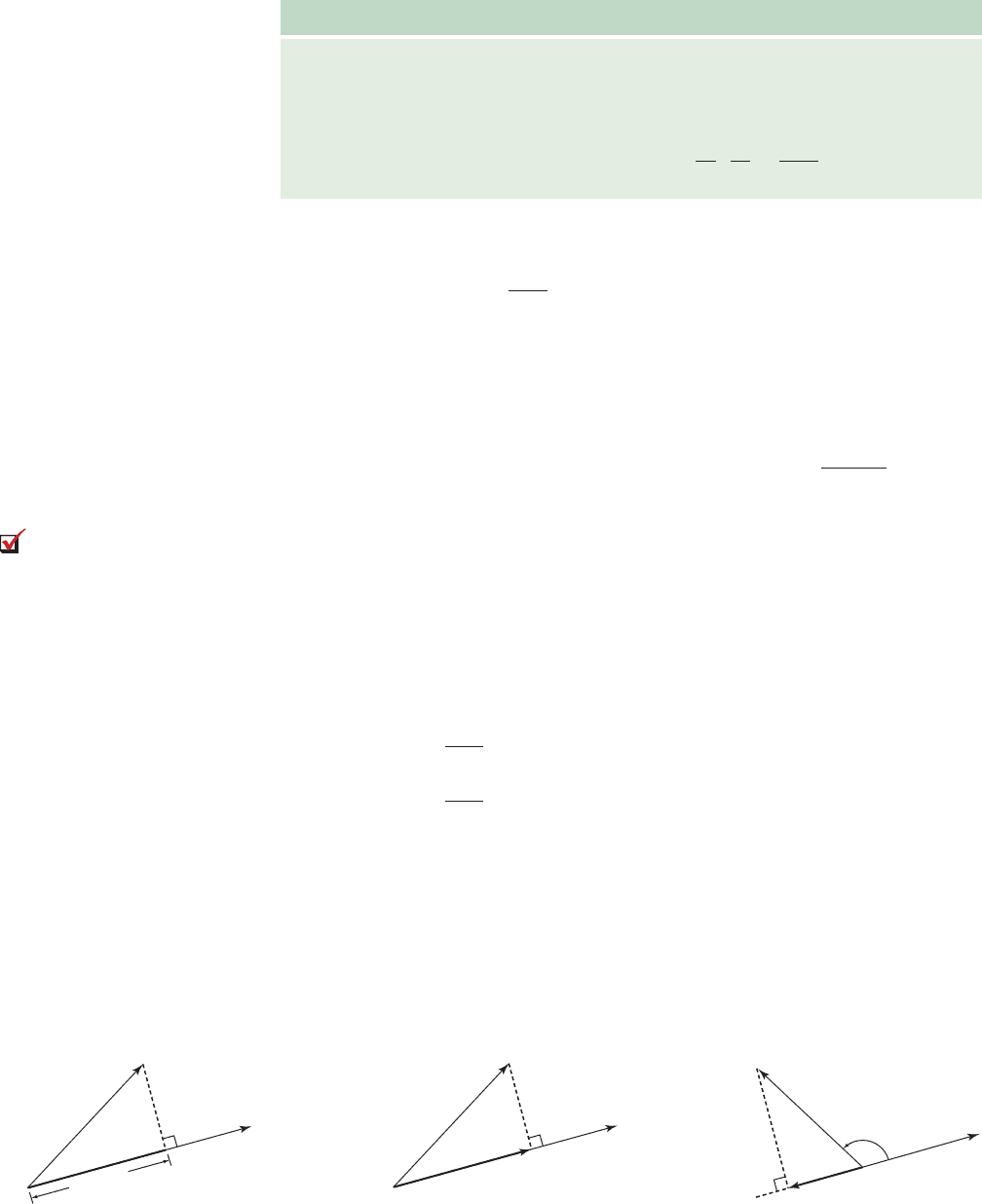
In work problems and other simple applications, it is enough to find and apply comp
v
u
(Figure 7.65). However, applications involving thrust and drag forces, tension and stress
limits in a cable, electronic circuits, and cartoon animations often require that we also
find the vector form of comp
v
u. This is called the projection of u along v or proj
v
u, and
is a vector in the same direction of v with magnitude comp
v
u (Figures 7.66 and 7.67).
v
u
#
v
v
comp
v
u
v
u
u
#
v
u
v
cos
u
cos
v
u
#
v comp
v
u
v
u
#
v
u
cos
u
#
v ac bd
v Hc, dI:u Ha, bI
v
,
u
#
v comp
v
u
comp
v
u
u
cos
v
#
u
u
2a
2
b
2
Hc, dI
#
Ha, bI
u
2
ca db
a
2
b
2
ac bd
u
#
u Ha, bI
#
Ha, bI u
#
v Ha, bI
#
Hc, dI
v Hc, dIu Ha, bI
cos
u
#
v
u
v
cos
u
u
#
v
v
u
#
v
u
v
0
#
u u
#
0 0
k1u
#
v2 ku
#
v u
#
kvw
#
1u v2 w
#
u w
#
v
u
#
u
u
2
u
#
v v
#
u
u
#
v 0,
Figure 7.65
Figure 7.66
Figure 7.67
D. You’ve just learned how
to compute dot products and
the angle between two
vectors
u
v
proj
v
u
(vector)
u
v
proj
v
u
(vector)
u
v
comp
v
u
(scalar)
College Algebra & Trignometry—
cob19529_ch07_753-765.qxd 12/30/08 17:26 Page 758
7-49 Section 7.4 Vector Applications and the Dot Product 759
By its design, the unit vector has a length of one and points in the same direction as
v, so proj
v
u can be computed as (see Example 7, Section 7.3). Using
equation (5) above and the properties shown earlier, an alternative formula for proj
v
u
can be found that is usually easier to simplify:
definition of a projection
substitute for comp
v
u
rewrite factors
Vector Projections
Given vectors u and v, the projection of u along v is the vector
EXAMPLE 9A
Finding the Projection of One Vector Along Another
Given and find proj
v
u.
Solution
To begin, find and .
projection of u along v
substitute for for , and for v
result
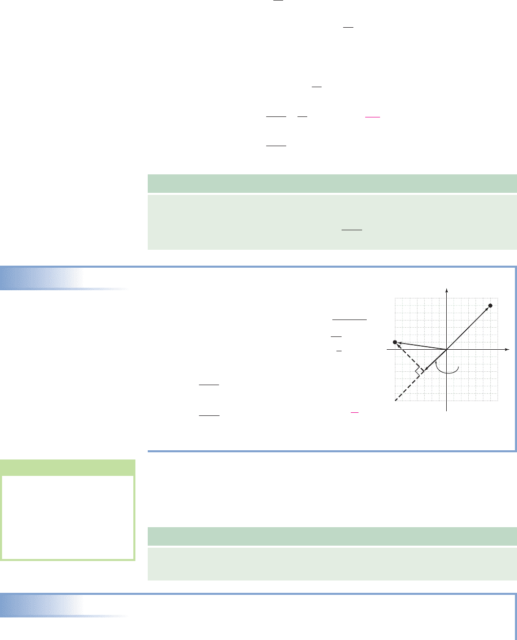
A useful consequence of computing proj
v
u is we can then resolve the vector u
into orthogonal components that need not be quadrantal. One component will be par-
allel to v and the other perpendicular to v (the dashed line in the diagram in Example
9A). In general terms, this means we can write u as the vector sum where
(note ).
Resolving a Vector into Orthogonal Components
Given vectors u, v, and proj
v
u, u can be resolved into the orthogonal components
u
1
and u
2
, where and .
EXAMPLE 9B
Resolving a Vector into Orthogonal Components
Given and resolve u into orthogonal components and ,
where and . Also verify
u
1
u
2
.u
2
vu
1
7v
u
2
u
1
v H8, 6I,u H2, 8I
u
2
u u
1
u u
1
u
2
, u
1
proj
v
u,
u
1
7vu
1
proj
v
u and u
2
u u
1
u
1
u
2
,
H3, 3I
H6, 6I
v
u
#
v, 172
36 a
36
72
b H6, 6I
proj
v
u a
u
#
v
v
2
bv
612
36
172
42 6
v
26
2
6
2
u
#
v H7, 1I
#
H6, 6I
v
u
#
v
v H6, 6I,u H7, 1I
proj
v
u a
u
#
v
v
2
bv
v
u
#
v
v
2
u
#
v
v
v
v
u
#
v
v
v
v
proj
v
u comp
v
u
v
v
comp
v
u
v
v
x
v
u
y
(7, 1)
(6, 6)
proj
v
u
WORTHY OF NOTE
Note that is the
shorter diagonal of the paral-
lelogram formed by the
vectors u and
This can also be seen in the
graph supplied for
Example 9B.
u
1
proj
v
u.
u
2
u u
1
College Algebra & Trignometry—
cob19529_ch07_753-765.qxd 12/30/08 17:26 Page 759
