Burton T. (et. al.) Wind energy Handbook
Подождите немного. Документ загружается.


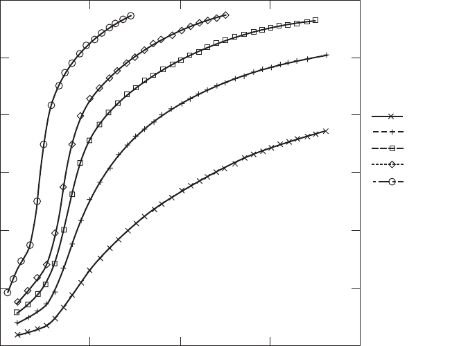
(1) Low solidity produces a broad, flat curve which means that the C
P
will change
very little over a wide tip speed ratio range but the maximum C
P
is low because
the drag losses are high (drag losses are roughly proportional to the cube of the
tip speed ratio).
(2) High solidity produces a narrow performance curve with a sharp peak making
the turbine very sensitive to tip speed ratio changes and, if the solidity is too
high, has a relatively low maximum C
P
. The reduction in C
P
max
is caused by stall
losses.
(3) An optimum solidity appears to be achieved with three blades, but two blades
might be an acceptable alternative because although the maximum C
P
is a little
lower the spread of the peak is wider and that might result in a larger energy
capture.
It might be argued that a good solution would be to have a large number of
blades of small individual solidity but this greatly increases production costs and
results in blades which are structurally weak and very flexible.
There are applications which require turbines of relatively high solidity, one is
the directly driven water pump and the other is the very small turbine used for
battery charging. In both cases it is the high starting torque (high torque at very low
tip speed ratios) which is of importance and this also allows small amounts of
power to be developed at very low wind speeds, ideal for trickle charging batteries.
0.5
0.4
0.3
0.2
0.1
0
One blade
Two blades
Three blades
Four blades
Five blades
C
P
0 5 10 15
λ
Figure 4.3 Effect of Changing Solidity
THE PERFORMANCE CURVES 175

4.1.3 The C
Q
– º curve
The torque coefficient is derived from the power coefficient simply by dividing by
the tip speed ratio and so it does not give any additional information about the
turbine’s performance. The principal use of the C
Q
–º curve is for torque assessment
purposes when the rotor is connected to a gear box and generator.
Figure 4.4 shows how the torque developed by a turbine rises with increasing
solidity. For modern high-speed turbines designed for electricity generation as low
a torque as possible is desirable in order to reduce gearbox costs. On the other hand
the multi-bladed, high-solidity turbine, developed in the nineteenth century for
water pumping, rotates slowly and has a very high starting torque coefficient
necessary for overcoming the torque required to start a positive displacement
pump.
The peak of the torque curve occurs at a lower tip speed ratio than the peak of the
power curve. For the highest solidity shown in Figure 4.4 the peak of the curve
occurs while the blade is stalled.
4.1.4 The C
T
– º curve
The thrust force on the rotor is directly applied to the tower on which the rotor is
supported and so considerably influences the structural design of the tower.
Generally, the thrust on the rotor increases with increasing solidity (Figure 4.5).
0.12
0.1
0.08
0.06
0.04
0.02
0
C
Q
0 5 10 15
λ
One blade
Two blades
Three blades
Four blades
Five blades
Figure 4.4 The Effect of Solidity on Torque
176
WIND-TURBINE PERFORMANCE
4.2 Constant Rotational Speed Operation
The majority of wind turbines currently installed generate electricity. Whether or
not these turbines are grid connected they need to produce an electricity supply
which is of constant frequency or else many common appliances will not function
properly. Consequently, the most common mode of operation for a wind turbine is
constant rotational speed. Connected to the grid a constant speed turbine is
automatically controlled whereas a stand-alone machine needs to have speed
control and a means of dumping excess power.
4.2.1 The K
P
–1=º curve
An alternative performance curve can be produced for a turbine controlled at
constant speed. The C
P
– º curve shows, non-dimensionally, how the power would
vary with rotational speed if the wind speed was held constant. The K
P
–1=º curve
describes, again non-dimensionally, how the power would change with wind speed
when constant rotational speed is enforced. K
P
is defined as
0.12
0.1
0.08
0.06
0.04
0.02
0
C
T
0 5 10 15 20
λ
One blade
Two blades
Three blades
Four blades
Five blades
Figure 4.5 The Effect of Solidity on Thrust
CONSTANT ROTATIONAL SPEED OPERATION 177
K
P
¼
Power
1
2
r(R)
3
A
d
¼
C
P
º
3
(4:1)
The C
P
– º and K
P
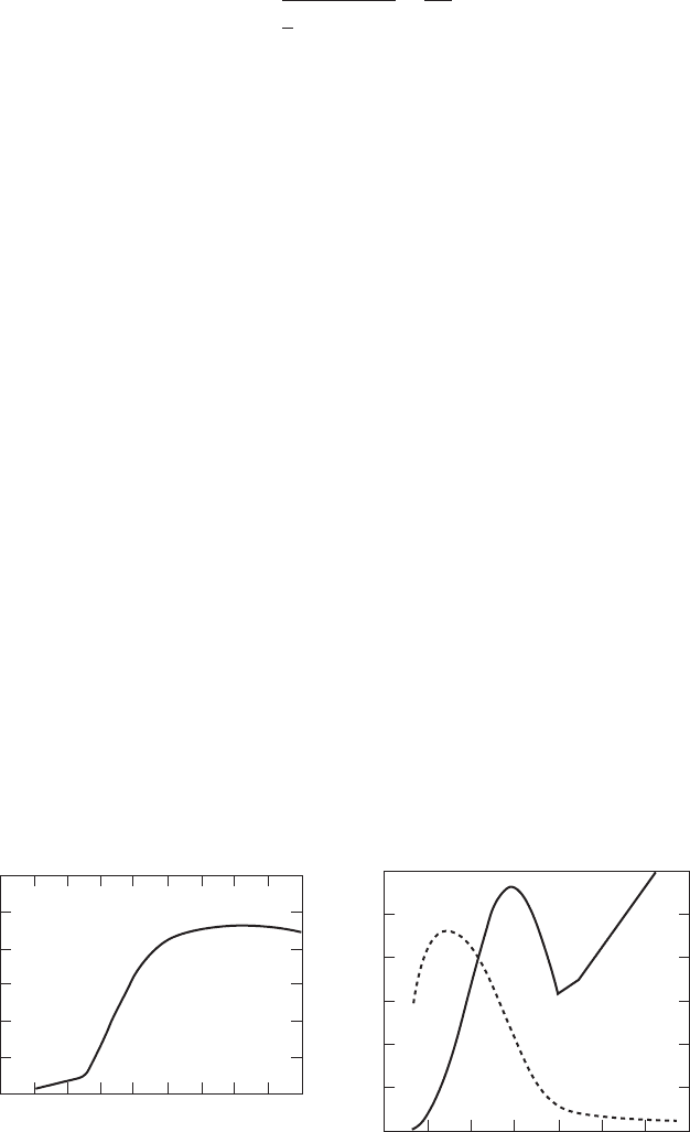
–1=º curves for a typical fixed-pitch wind turbine are shown
in Figure 4.6. The K
P
–1=º curve, as stated above, has the same form as the power
– wind speed characteristic of the turbine. The efficiency of the turbine (given by
the C
P
– º curve) varies greatly with wind speed, a disadvantage of constant speed
operation, but it should be designed such that the maximum efficiencies are
achieved at wind speeds where there is the most energy available.
4.2.2 Stall regulation
An important feature of this K
P
–1=º curve is that the power, initially, falls off once
stall has occurred and then gradually increases with wind speed. This feature
provides an element of passive power output regulation, ensuring that the gen-
erator is not overloaded as the wind speed increases. Ideally, the power should rise
with wind speed to the maximum value and then remain constant regardless of the
increase in wind speed; this is called perfect stall regulation. However, stall
regulated turbines do not exhibit the ideal, passive stall behaviour.
Stall regulation provides the simplest means of controlling the maximum power
generated by a turbine to suit the sizes of the installed generator and gearbox and
until recently, at the time of writing, is the most commonly adopted control method.
The principal advantage of stall control is simplicity but there are significant
disadvantages. The power versus wind speed curve is fixed by the aerodynamic
characteristics of the blades, in particular the stalling behaviour. The post stall
power output of a turbine varies very unsteadily and in a manner which, so far,
defies prediction, see Figure 4.13, for example. The stalled blade also exhibits low
vibration damping because the flow about the blade is unattached to the low
pressure surface and blade vibration velocity has little effect on the aerodynamic
forces. The low damping can give rise to large vibration displacement amplitudes
0.6
0.5
0.4
0.3
0.2
0.1
0
0.06
0.05
0.04
0.03
0.02
0.01
0
0.6
0.5
0.4
0.3
0.2
0.1
0
C
P
C
P
C
P
K
P
K
P
0 1 2 3 4 5 6 7 8 9
0 0.1 0.2 0.3 0.4 0.5 0.6 0.7
λ
l/λ
Figure 4.6 Non-dimensional Performance Curves for Constant Speed Operation
178
WIND-TURBINE PERFORMANCE
which will inevitably be accompanied by large bending moments and stresses,
causing fatigue damage. When parked in high, turbulent winds a rotor with fixed
pitch blades may well be subject to large aerodynamic loads which cannot be
alleviated by adjusting (feathering) the blade pitch angle. Consequently, a fixed-
pitch, stall-regulated turbine experiences more severe blade and tower loads than a
pitch regulated turbine.
4.2.3 Effect of rotational speed change
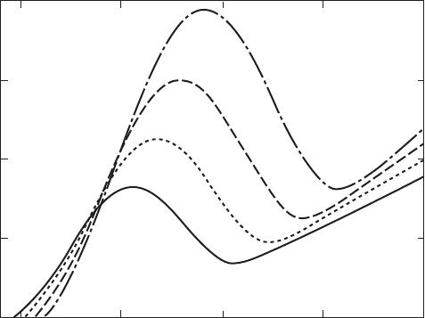
The power output of a turbine running at constant speed is strongly governed by
the chosen, operational rotational speed. If a low rotation speed is used the power
reaches a maximum at a low wind speed and consequently it is very low. To extract
energy at wind speeds higher than the stall peak the turbine must operate in a
stalled condition and so is very inefficient. Conversely, a turbine operating at a high
speed will extract a great deal of power at high wind speeds but at moderate wind
speeds it will be operating inefficiently because of the high drag losses. Figure 4.7
demonstrates the sensitivity to rotation speed of the power output – a 33 percent
increase in r.p.m. from 45 to 60 results in a 150 percent increase in peak power,
reflecting the increased wind speed at which peak power occurs at 60 r.p.m.
At low wind speeds, on the other hand there is a marked fall in power with
increasing rotational speed as shown in Figure 4.8. In fact, the higher power
available at low wind speeds if a lower rotational speed is adopted has led to two-
speed turbines being built. Operating at one fixed speed which maximizes energy
capture at wind speeds at, or above, the average level will result in a rather high
cut-in wind speed, the lowest wind speed at which generation is possible. Employ-
80
60
40
20
0
Electrical power (kW)
0 5 10 15 20 25
Wind speed (m/s)
45 rpm
50 rpm
55 rpm
60 rpm
Figure 4.7 Effect on Extracted Power of Rotational Speed
CONSTANT ROTATIONAL SPEED OPERATION 179
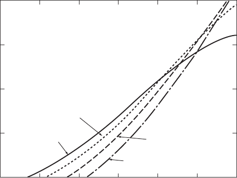
ing a lower rotational speed at low wind speeds reduces the cut-in wind speed and
increases energy capture. The increased energy capture is, of course, offset by the
cost of the extra machinery.
4.2.4 Effect of blade pitch angle change
Another parameter which affects the power output is the pitch setting angle of the
blades
s
. Blade designs almost always involve twist but the blade can be set at the
root with an overall pitch angle. The effects of a few degrees of pitch are shown in
Figure 4.9.
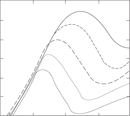
Small changes in pitch setting angle can have a dramatic effect on the power
output. Positive pitch angle settings increase the design pitch angle and so decrease
the angle of incidence. Conversely, negative pitch angle settings increase the angle of
incidence and may cause stalling to occur as shown in Figure 4.9. A turbine rotor
designed to operate optimally at a given set of wind conditions can be suited to other
conditions by appropriate adjustments of blade pitch angle and rotational speed.
4.2.5 Pitch regulation
Many of the shortcomings of fixed pitch/passive stall regulation can be overcome
by providing active pitch angle control. Figure 4.9 shows the sensitivity of power
output to pitch angle changes.
The most important application of pitch control is for power regulation but pitch
control has other advantages. By adopting a large positive pitch angle a large
Electrical power (kW)
0 5 6 7 8 9 10
Wind speed (m/s)
40
30
20
10
0
55 rpm
60 rpm
50rpm
45 rpm
Figure 4.8 Effect on Extracted Power of Rotational Speed at Low Wind Speeds
180
WIND-TURBINE PERFORMANCE
starting torque can be generated as a rotor begins to turn. A 908 pitch angle is
usually used when shutting down because this minimises the rotor idling speed at
which the parking brake is applied. At 908 of positive pitch the blade is said to be
‘feathered’. The principal disadvantages of pitch control are reliability and cost.
Power regulation can be achieved either by pitching to promote stalling or pitching
to feather which reduces the lift force on the blades by reducing the angle of attack.
4.2.6 Pitching to stall
Figure 4.9 shows the power curves for a turbine rated at 60 kW, which is achieved
at 12 m/s. At wind speeds below the rated level the blade pitch angle is kept at 08.
As rated power is reached only a small negative pitch angle, initially of about 28,is
necessary to promote stalling and so to limit the power to the rated level. As the
wind speed increases small adjustments in both the positive and negative directions
are all that are needed to maintain constant power. The small sizes of the pitch
angle adjustments make pitching to stall very attractive to designers but the blades
have the same damping and fatigue problems as fixed pitch turbines.
4.2.7 Pitching to feather
By increasing the pitch angle as rated power is reached the angle of attack can be
reduced. A reduced angle of attack will reduce the lift force and the torque. The
5 10 15 20 25
Electrical power (kW)
120
100
80
60
40
20
0
Wind speed
(
m/s
)
-4
-2
0
+2
+4
Figure 4.9 Effect on Extracted Power of Blade Pitch Set Angle
CONSTANT ROTATIONAL SPEED OPERATION 181
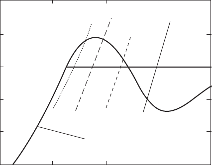
flow around the blade remains attached. Figure 4.10 is for the same turbine as
Figure 4.9 but only the zero degree power curve is shown below the rated level.
Above the rated level fragments of power curves for higher pitch angles are shown
as they cross the rated power line; the crossing points give the necessary pitch
angles to maintain rated power at the corresponding wind speeds. As can be seen
in Figure 4.10, the required pitch angles increase progressively with wind speed
and are generally much larger than is needed for the pitching to stall method. In
gusty conditions large pitch excursions are needed to maintain constant power and
the inertia of the blades will limit the speed of the control system’s response.
Because the blades remain unstalled if large gusts occur at wind speeds above the
rated level large changes of angle of attack will take place with associated large
changes in lift. Gust loads on the blades can therefore be more severe than for
stalled blades. The advantages of the pitching to feather method are that the flow
around the blade remains attached, and so well-understood, and provides good,
positive damping. Feathered blade parking and assisted starting are also available.
Pitching to feather has been the preferred pitch control option mainly because the
blade loads can be predicted with more confidence than for stalled blades.
4.3 Comparison of Measured with Theoretical
Performance
The turbine considered in this section is run at constant rotational speed, the most
common mode of operation, because this allows electricity to be generated at
constant frequency. More detail about this method of operation will be discussed in
the next section but the main feature is that there is, theoretically, a unique power
output for a given wind speed.
100
80
60
40
20
0
Wind s
p
eed
(
m/s
)
5 10 15 20 25
Electrical power (kW)
0 Power curve
+6
+12
+18
+24
Figure 4.10 Pitching to Feather Power Regulation Requires Large Changes of Pitch Angle
182
WIND-TURBINE PERFORMANCE

When the turbine was under test the chosen rotational speed was 44 r.p.m.
Energy output and wind speed were measured over 1 min time intervals and the
average power and wind speed determined. The test was continued until a
sufficient range of wind speeds had been covered. The results were then sorted in
‘bins’ 0.5 m/s of wind speed wide and a fairly smooth power versus wind-speed
curve was obtained as shown in Figure 4.11. The turbine has a diameter of 17 m and
would be expected to produce rather more power than shown above if operated at
a higher rotational speed.
From the data in Figure 4.11 the C
P
– º curve can be derived. The tip speed of the
blades is 44 3 =30 rad=s 3 8:5m ¼ 39:2m=s, the swept area is 3 8:5
2
¼ 227 m
2
and the air density was measured (from air pressure and temperature readings) at
1:19 kg=m
3
. Therefore
º ¼
39:2
Windspeed
and C
P
¼
Power º
3
1
2
1:19 39:2
3
227
The mechanical and electrical losses were estimated at 5.62 kW and this value was
used to adjust the theoretical values of C
P
. The resulting comparison of measured
and theoretical results are shown in Figure 4.12.
This comparison looks reasonable and shows that the theory is reliable but the
quality of the theoretical predictions really relies upon the quality of the aerofoil
data. The blade and aerofoil design are the same as given in Section 3.9.
One last point should be made before classifying the theory as complete: it would
be as well to look at the raw, 1 min averages data, which was reduced down by the
binning process and is shown in Figure 4.12. In the post stall region there seems to
be a much more complex process taking place than the simple theory predicts and
this could be caused by unsteady aerodynamic effects.
Wind s
p
eed
(
m/s
)
0 5 10 15 20 25 30
Electrical power (kW)
60
50
40
30
20
10
0
Figure 4.11 Power versus Wind Speed Curve from the Binned Measurements of a Three-
blade Stall Regulated Turbine
COMPARISON OF MEASURED WITH THEORETICAL PERFORMANCE 183

4.4 Variable-speed Operation
If the speed of the rotor can be continuously adjusted such that the tip speed ratio
remains constant at the level which gives the maximum C
P
then the efficiency of
the turbine will be significantly increased. Active pitch control is necessary to
maintain a constant tip speed ratio but only in the process of adjustment of
0 2 4 6 8 10
Tip speed ratio
Power coefficient
0 5 10 15 20 25 30
Wind speed (m/s)
Electrical power (kW)
Measurement
Theory
Measurement
Theory
0.4
0.3
0.2
0.1
0
60
40
20
0
Figure 4.12 Comparison of Measured and Theoretical Performance Curves
60
50
40
30
20
10
0
0 5 10 15 20 25 30
Wind s
p
eed
(
m/s
)
Electrical power (kW)
ESE
SE
S
SSW
SW
WSW
W
Wind direction
Figure 4.13 Measured Raw Results of a Three-blade Wind Turbine
184
WIND-TURBINE PERFORMANCE
