Bryan L. Programmable controllers. Theory and implementation
Подождите немного. Документ загружается.


189
CHAPTER
7
The Analog
Input/Output System
Industrial Text & Video Company 1-800-752-8398
www.industrialtext.com
SECTION
2
Components
and Systems
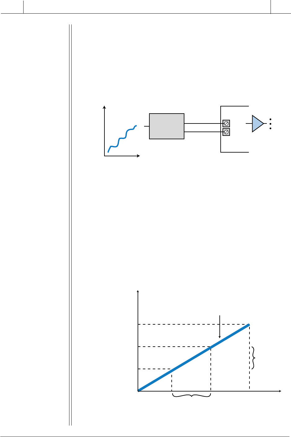
Figure 7-6. Conversion of an analog signal by a transmitter and transducer.
Due to the many types of transducers available, analog input modules have
several standard electrical input ratings. Table 7-2 lists the standard current
and voltage ratings for analog interfaces. Note that analog interfaces can be
either unipolar (positive voltage only—i.e., 0 to +5 VDC) or bipolar (nega-
tive and positive voltages—i.e., –5 to +5 VDC).
Table 7-2. Typical analog input interface ratings.
7-3 ANALOG INPUT DATA REPRESENTATION
Field devices that provide an analog output as their signal (analog sensors or
transducers) are usually connected to transmitters, which in turn, send the
analog signal to the module. A transducer converts a field device’s variable
(i.e., pressure, temperature, etc.) into a very low-level electrical signal
(current or voltage) that can be amplified by a transmitter and then input into
the analog interface (see Figure 7-6).
Input Interfaces
4–20 mA
0 to +1 volts DC
0 to +5 volts DC
0 to +10 volts DC
1 to +5 volts DC
± 5 volts DC
± 10 volts DC
1C
1
2
2C
3
3C
4
4C
Volts DC
Process
0
10
Time
Physical
Signal
Analog
Input
Module
Signal Common
0 to 10 Volts
DC Signal
Sensor
Transducer
Transmitter
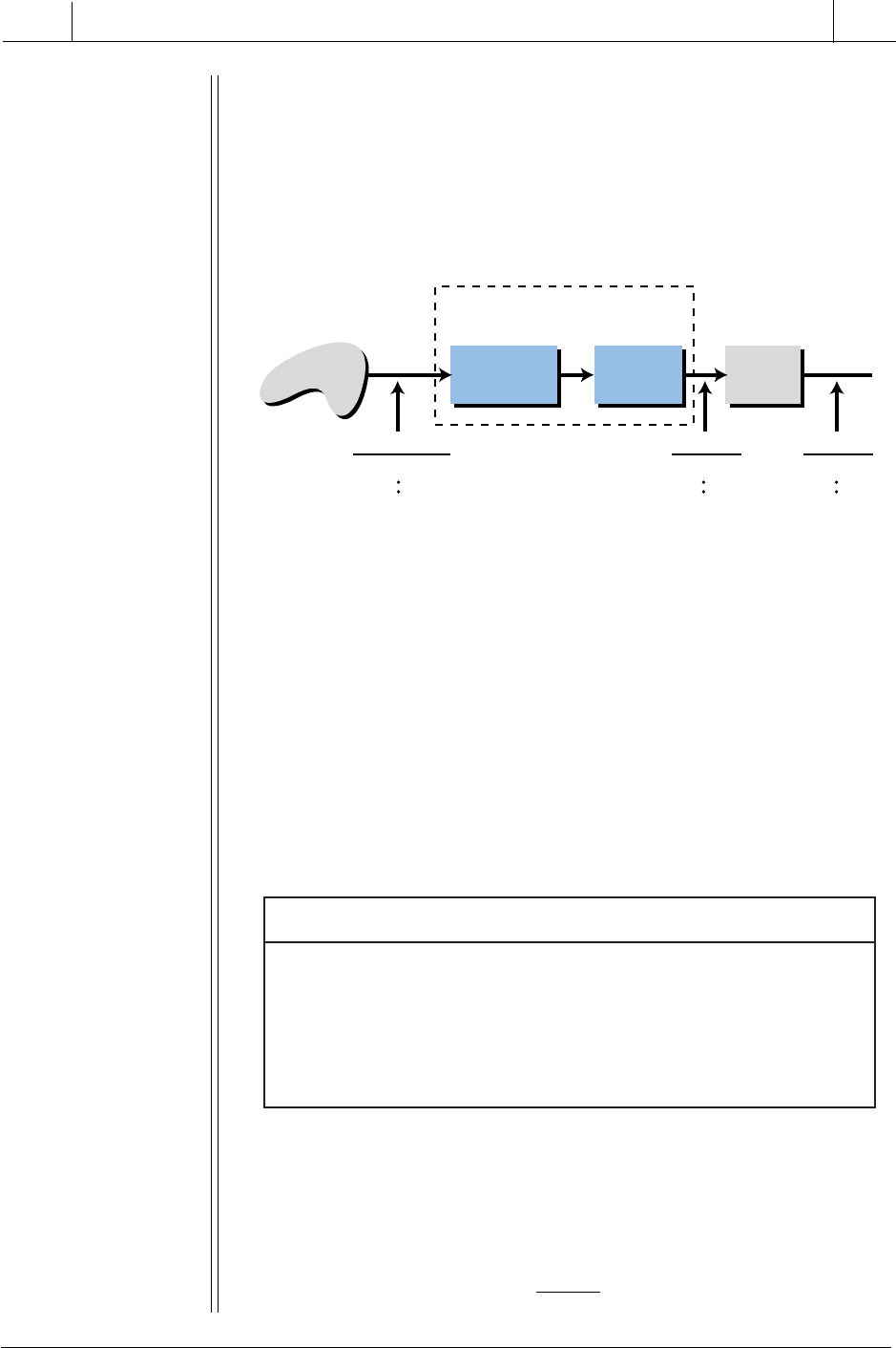
As mentioned earlier, an analog input module transforms an analog input
signal via a sensor/transmitter unit into a discrete value that is readily
understandable by man and machine (see Figure 7-7). This transformed value
is the digital equivalent of the variable analog signal (e.g., pressure in psi)

190
SECTION
2
Components
and Systems
Industrial Text & Video Company 1-800-752-8398
www.industrialtext.com
CHAPTER
7
The Analog
Input/Output System
measured by the field device. The field sensing device sends a very low-level
current or voltage analog input to the transmitter. The transmitter (sometimes
incorporated in the same unit as the sensor) sends this information to the input
module as an amplified current or voltage proportional to the signal being
measured. Next, the analog input interface digitizes the current or voltage by
converting it into an equivalent binary number. The interface then sends the
digitized signal to the controller. Thus, the binary value that the PLC receives
is the digital equivalent of the incoming analog signal.
Figure 7-7. Transformation of an analog signal into a binary or BCD value.
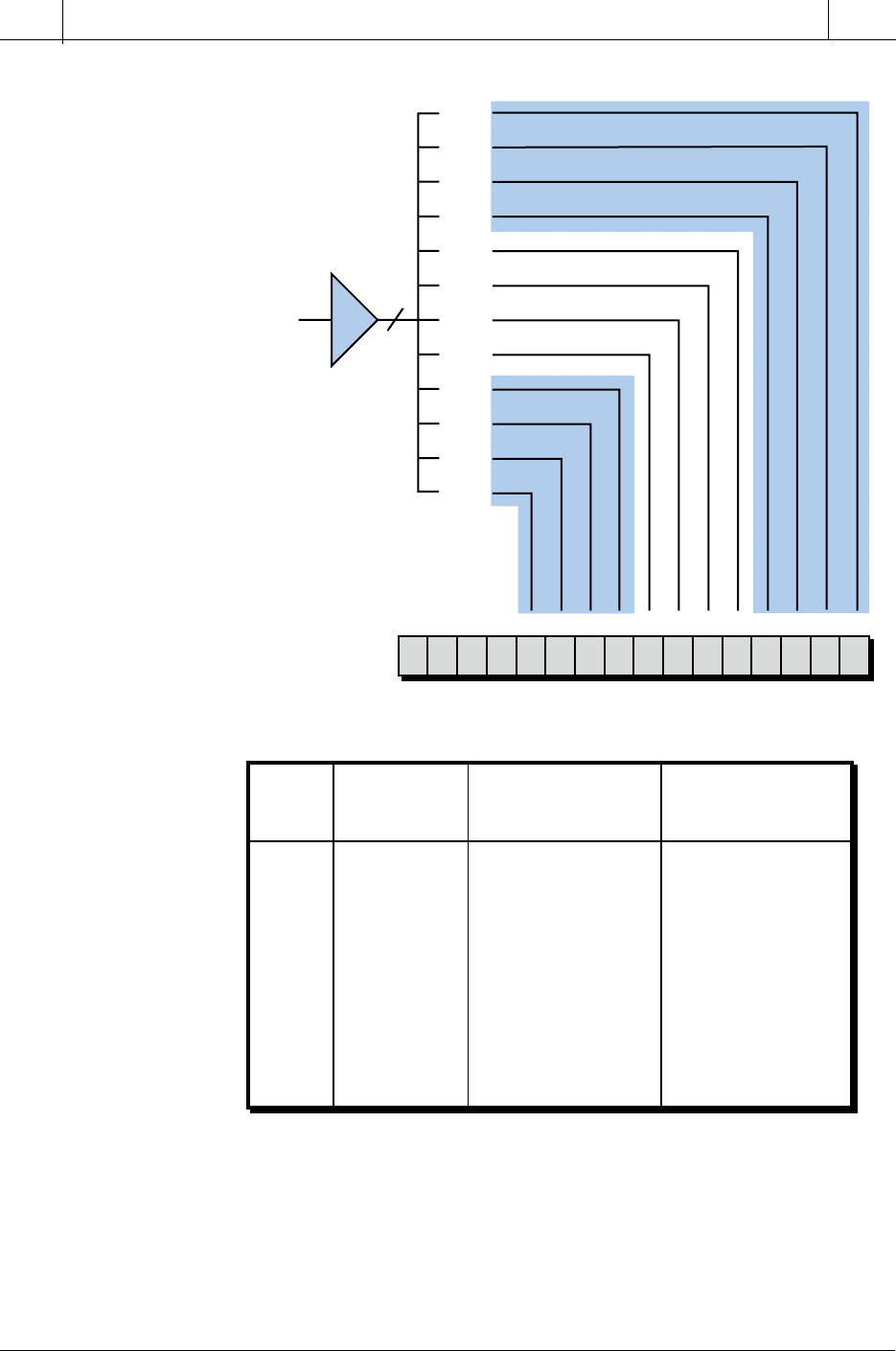
An analog-to-digital converter (A/D or ADC) performs the signal conver-
sion in an analog input module. The converter divides, or digitizes, the input
signal into many digital counts, which represent the magnitude of the current
or voltage. This division of the input signal is called resolution. The
resolution of the module indicates how many parts the module’s A/D will
divide the input signal into; it is given as a function of how many bits the A/D
uses during conversion. For example, if an A/D breaks down an input signal
using 12 bits or 4096 parts (i.e., 2
12
= 4096) as shown in Figure 7-8, it has a
12-bit resolution (i.e., a 12-bit binary number with a value ranging from 0000
to 4095 decimal will represent the signal). In this case, the manufacturer could
then use the remaining bits (bits 14–17) as status monitoring bits, representing
module conditions such as active, OK, channel operating, etc.
An A/D converter transfers its digital-equivalent values to the processor,
which in turn, makes them available for use in register or word locations. The
format of these values varies according to the format used by the PLC;
however, the most common formats are binary and BCD. In BCD format, the
module or processor must perform an extra linearity computation to provide
a valid BCD number.
Some PLCs also offer direct scale conversion of the input signal to equivalent
engineering units (0 to 9999). Table 7-3 illustrates the conversion of psi
values into engineering units and their decimal equivalents. The module
Analog
Input
Transmitter
Sensor
(Transducer)
Senses
physical
signal
Low-level
voltage of
current
Amplified voltage
or current
compatible with
analog input interface
Digitized
value
(counts)
Physical
Signal
To
Processor
Analog input
variable signal
Discrete
value to
PLC in binary
or BCD (counts)
Process

191
CHAPTER
7
The Analog
Input/Output System
Industrial Text & Video Company 1-800-752-8398
www.industrialtext.com
SECTION
2
Components
and Systems
Figure 7-8. An analog-to-digital converter with 12-bit resolution.
Table 7-3. Psi values translated into decimal equivalents and engineering units.
interprets the incoming 0 to 500 psi signal variable as a voltage ranging from
0 to 10 VDC. It then converts this voltage into an equivalent decimal value.
A decimal value of 0 corresponds to 0 psi, while a decimal value of 4095
corresponds to 500 psi. The following examples illustrate how an A/D
computes equivalent analog counts for an analog field signal.
171615141312111076543210
Bit 0
Bit 1
Bit 2
Bit 3
Bit 4
Bit 5
Bit 6
Bit 7
Bit 8
Bit 9
Bit 10
Bit 11
PLC Register
Analog-to-
Digital
Converter
12
Bits
Analog Input
Signal
(voltage or
current from
transmitter/
transducer)
A/D
A/D
Analog Voltage
Input
Digital Representation
Engineering Units
0000-9999
Digital Representation
Decimal Scale
0-4095
Pressure
psi
0
50
100
150
200
250
300
350
400
450
500
0V
1V
2V
3V
4V
5V
6V
7V
8V
9V
10V
000
100
200
300
400
500
600
700
800
900
999
0
410
819
1229
1638
2047
2457
2866
3276
3685
4095
0000
1000
2000
3000
4000
5000
6000
7000
8000
9000
9999
Engr. Units

192
SECTION
2
Components
and Systems
Industrial Text & Video Company 1-800-752-8398
www.industrialtext.com
CHAPTER
7
The Analog
Input/Output System
Figure 7-9. An A/D and an analog input module connected to a temperature-
sensing device.
EXAMPLE 7-2
An input module, which is connected to a temperature transducer, has
an A/D with a 12-bit resolution (see Figure 7-9). When the temperature
transducer receives a valid signal from the process (100 to 600°C), it
provides, via a transmitter, a +1 to +5 VDC signal compatible with the
analog input module.
(a) Find the equivalent voltage change for each count change (the
voltage change per degree Celsius change) and the equivalent
number of counts per degree Celsius, assuming that the input module
transforms the data into a linear 0 to 4095 counts, and (b) find the same
values for a module with a 10-bit resolution.
S
OLUTION
(a) The relationship between temperature, voltage signal, and module
counts is:
The changes (∆) in temperature, voltage, and input counts are 500°C,
4 VDC, and 4095 counts. Therefore, the voltage change for a 1°C
temperature change is:
∆500 ° C =∆4 VDC
1° C =
4 VDC
500
= 8.0 mVDC
erutarepmeTlangiSegatloVstnuoCtupnI
001°CCDV10
•••
•••
•••
006°CCDV55904
Analog
Input
Transmitter
Sensor
(Transducer)
Temp Range
100
˚
C
600
˚
C
Temp
˚
C To PLC
Sensor and transmitter
in one unit
Voltage
1 VDC
5 VDC
Counts
0
4095
Process

193
CHAPTER
7
The Analog
Input/Output System
Industrial Text & Video Company 1-800-752-8398
www.industrialtext.com
SECTION
2
Components
and Systems
The change in voltage for each input count is:
The changes in temperature, voltage, and counts are 500°C, 4 VDC,
and 1023 counts. The voltage change per degree will be the same as
in part (a) and is:
Therefore, the corresponding number of counts per degree Celsius is:
(b) A 10-bit resolution A/D will digitize the unipolar input signal into
1024 counts (i.e., 2
10
= 1024 counts, ranging from 0000 to 1023). The
relationship between temperature, voltage signal, and counts is:
∆∆4095 4
1
4
4095
0 9768
counts VDC
count
VDC
mVDC
=
==.
∆∆500 4095
1
4095
500
819
°=
°= =
C counts
C
counts
counts.
The change in voltage per input count is:
Thus, the corresponding number of counts per degree Celsius is:
∆∆500 4
1
4
500
80
°=
°= =
C VDC
C
VDC
mVDC.
∆∆1023 4
1
4
1023
391
counts VDC
count
VDC
mVDC
=
==.
∆∆500 1023
1
1023
500
2 046
°=
°= =
C counts
C
counts
counts.
erutarepmeTlangiSegatloVstnuoCtupnI
001°CCDV10
•••
•••
•••
005°CCDV44201

194
SECTION
2
Components
and Systems
Industrial Text & Video Company 1-800-752-8398
www.industrialtext.com
CHAPTER
7
The Analog
Input/Output System
Figure 7-10. Temperature transducer/transmitter connected to an input module.
Figure 7-11. Relationship between counts and input signal.
EXAMPLE 7-3
A temperature transducer/transmitter (see Figure 7-10) provides a 0–
10 VDC voltage signal that is proportional to the temperature variable
being measured. The temperature measurement ranges between 0
and 1000°C. The analog input module accepts a 0–10 VDC unipolar
signal range and converts it to a range of 0–4095 counts. The process
application where this signal is being used detects low and high
alarms at 100°C and 500°C, respectively.
Find (a) the relationship (i.e., equation of the line) between the input
variable signal (temperature) and the counts being measured by the
PLC module and (b) the equivalent number of counts for each of the
alarm temperatures specified.
S
OLUTION
(a) Figure 7-11 shows the relationship between counts and the input
signal in volts and degrees Celsius. Line
Y
describes the numerical
relationship between the input signal and the number of counts
(assuming a linear relationship).
1000°C
0°C
time
Transducer
0°C to 1000°C
0–10 Volts DC
Signal Return
Input
Common
Analog Input
Module
A/D
0 counts
4095 counts
˚C
1000
High 500
Low 100
0
10 VDC
0 VDC
Y
Alarm Count
Detection Range
Alarm
Detection
Range ˚C
40950
X
line
Y
˚C
=
mx
counts
+
b

195
CHAPTER
7
The Analog
Input/Output System
Industrial Text & Video Company 1-800-752-8398
www.industrialtext.com
SECTION
2
Components
and Systems
To find the relationship between temperature and counts, find the
numerical representation of the equation for line
Y
. This equation takes
the form
Y = mX + b
(see Appendix E), where
m
is the slope of the line
and is described by:
and
Y
2
,
Y
1
,
X
2
, and
X
1
are known points. The value
b
is the value of
Y,
or °C, when
X,
or counts, equals 0. This value can be computed as:
where
Y
and
X
are values at known points (i.e., at 0°C and 0 counts).
When
X
is at 0 counts,
Y
is at 0°C; therefore:
Substituting the derived values for
m
and
b
into the equation
Y = mX
+
b
produces the equation of line
Y
:
Using 4095 counts and 1000°C as the
X
and
Y
values when comput-
ing
b
would have derived the same equation (try it as an exercise).
(b) Based on the equation of line
Y
, the number of counts for each
alarm range is:
So, for the
Y
°C
values of 100°C and 500°C, the
X
values are:
m
YY
XX
=
−
−
=
°−°
−
=
−
−
=
21
21
21
21
1000 0
4095 0
1000
4095
CC
count count
bY mX
=−
°C counts
b
=−
=
0
1000
4095
0
0
YmXb
YX
X
=+
=+
=
°C counts
counts
1000
4095
0
1000
4095
YX
X
Y
°
°
=
=
C counts
counts
C
1000
4095
4095
1000
()
X
X
counts at100 C
counts at 500 C
counts
counts
°
°
==
==
4095100
1000
409 5
4095 500
1000
2047 5
()
.
()
.

196
SECTION
2
Components
and Systems
Industrial Text & Video Company 1-800-752-8398
www.industrialtext.com
CHAPTER
7
The Analog
Input/Output System
Thus, the count value for 100°C is 409.5 counts and for 500°C is 2047.5
counts. Since count values must be whole numbers, rounding these
values off yields 410 and 2048 counts, respectively. Therefore, at a
count of 410, the low-level temperature alarm would be enabled; and
at a count of 2048, the high-level temperature alarm would be enabled.
Another method for solving this problem is to determine the number of
counts that are equivalent to 1°C. A change of 1000°C per 4095 counts
can be expressed as:
∆counts
∆degrees
=
max counts −min counts
max degrees −min degrees
=
4095 − 0
1000 − 0
= 4.095
Therefore, each degree is equivalent to 4.095 counts. The count value
for 500°C would be (500)(4.095) = 2047.5 and for 100°C would be
(100)(4.095) = 409.5. Rounding off these values yields 2048 and 410
counts, respectively—the same values we computed before. If the
counts had not started at 0, an offset count addition would have been
necessary for computing the number of counts per degree.
7-4 ANALOG INPUT DATA HANDLING
The previous section showed how an analog input module transforms an
analog field signal into a discrete signal. Once the module digitizes the signal
into binary counts, the processor can read the value and use the information.
During the input reading section of the scan, the processor reads the value
from the module and transfers the information to a location specified by the
user. This location is usually a word or register storage area or an input
register. The processor enters the count value into memory using instructions
that differ from those used by standard discrete input modules, yet are similar
to those used by multibit discrete input interfaces (see Figure 7-12).
Most analog modules provide more than one channel, or input, per interface.
Therefore, they can connect to several input signals, as long as the signals are
compatible with the module. The analog instructions used in PLCs take
advantage of this multiple channel capability, inputting several values at a
time into registers or words. Examples of these instructions are analog in,
block transfer in, block in, and location in instructions (see Chapter 9). Some
programmable controller manufacturers use other instructions, such as arith-
metic instructions, to obtain count values from the analog module’s address.
When a processor executes the instruction to read an analog input, it obtains
the module’s data during the next I/O scan and places the data in the
destination register specified in the instruction. If multiple channels are to be

197
CHAPTER
7
The Analog
Input/Output System
Industrial Text & Video Company 1-800-752-8398
www.industrialtext.com
SECTION
2
Components
and Systems
Figure 7-12. Process for inputting analog data to a word location.
Voltage Signal
Return Line
Analog
Input
Module
Analog Input
Instruction
Used
A/D
12 Bits
001 11 1 110000
0000001111110000
Register
Holding
Analog
Value
Analog Variable
not used
Data Table
Word Location
or
Register Storage
Location
Analog
Transducer

198
SECTION
2
Components
and Systems
Industrial Text & Video Company 1-800-752-8398
www.industrialtext.com
CHAPTER
7
The Analog
Input/Output System
read, the processor reads and stores one channel every scan. This does not
cause a delay in signal processing, since the scan is very fast and the signals
are rather slow in nature.
A processor can determine whether or not the module inserted in the enclosure
is analog. If the module is analog, the processor will read the available data
in groups of 16 bits, with 12 bits (depending on the resolution) displaying the
analog value in binary or BCD. Some controllers may provide diagnostic
information about the module and its channels by reading an extra word or
register after all channels are input.
The physical location of a module within the rack or enclosure (see Chapter
5 for I/O enclosures) defines its address location. Figure 7-13 illustrates an
example of an address for an analog module location. A typical instruction
will reference a module’s address location by specifying the module’s rack
and slot numbers, the number of channels or analog inputs used, and the
starting register destination address. If a module uses eight channels and the
destination storage register starts at address 200
8
, the last storage register will
be at address 207
8
(see Figure 7-14). The module may also send a status
register; in which case, the bits in this register will indicate the status of each
channel. The processor assigns the register range automatically according to
the number of channels; however, the programmer must remember not to
overlap the usage of already assigned registers.
Figure 7-13. An addressed analog module.
Processor and
Power Supply
00 01 02 03 04 05 06 07 Slot
Rack 0
Input
Instruction Enable
Destination
Register 200
Rack 0
Slot 03
Number of
Channels 8
