Bird R.B., Stewart W.E., Lightfoot E.N. Transport Phenomena
Подождите немного. Документ загружается.

315.5
Use of the Macroscopic Balances to Solve Unsteady-State Problems
467
SOLUTION
heating coil, and the overall heat transfer coefficient is 100 Btu/hr ft2
.
F.
What is the temper-
ature of the water when the tank is filled?
We shall make the following assumptions:
a.
The steam temperature is uniform throughout the coil.
b.
The density and heat capacity do not change very much with temperature.
*
h
c.
The fluid is approximately incompressible so that
C,
=
C,.
d.
The agitator maintains uniform temperature throughout the liquid.
e.
The heat transfer coefficient is independent of position and time.
f.
The walls of the tank are perfectly insulated so that no heat loss occurs.
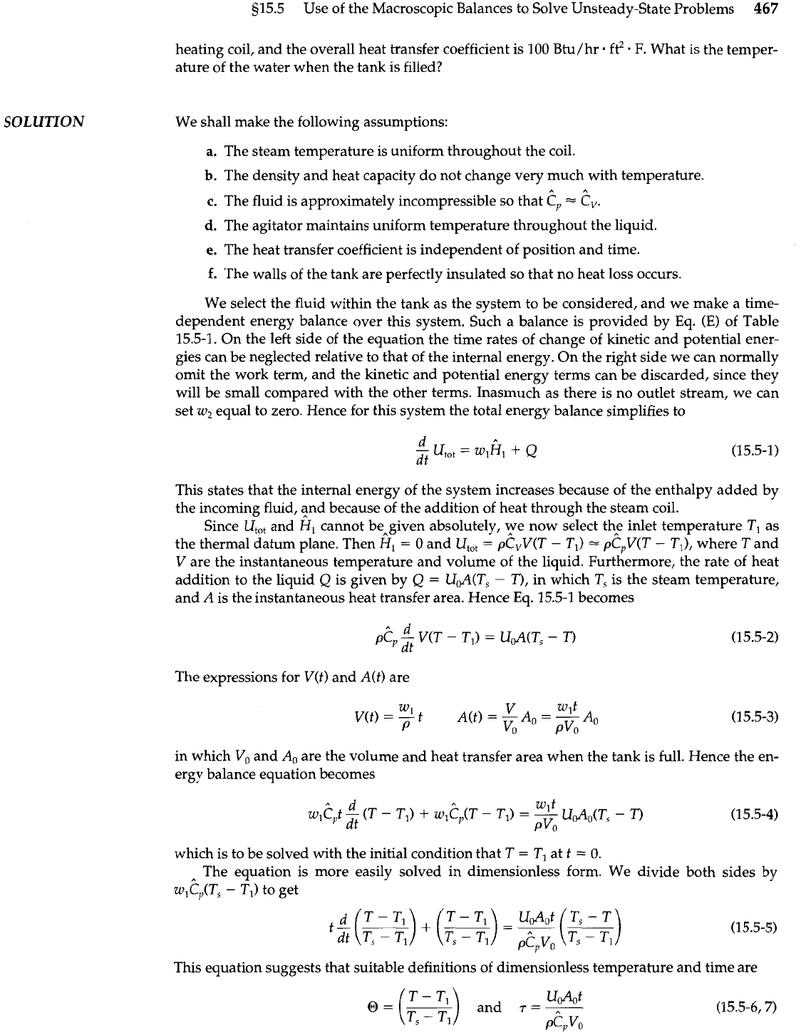
We select the fluid within the tank as the system to be considered, and we make a time-
dependent energy balance over this system. Such a balance is provided by Eq.
(E)
of Table
15.5-1. On the left side of the equation the time rates of change of kinetic and potential ener-
gies can be neglected relative to that of the internal energy. On the right side we can normally
omit the work term, and the kinetic and potential energy terms can be discarded, since they
will be small compared with the other terms. Inasmuch as there is no outlet stream, we can
set
w2
equal to zero. Hence for this system the total energy balance simplifies to
This states that the internal energy of the system increases because of the enthalpy added by
the incoming fluid, and because of the addition of heat through the steam coil.
Since
U,,,
and
H,
cannot bengiven absolutely, ye now select th? inlet temperature
TI
as
the thermal datum plane. Then
H1
=
0
and
U,,,
=
pCVV(T
-
TI)
=
pCpV(T
-
TI),
where
T
and
V
are the instantaneous temperature and volume of the liquid. Furthermore, the rate of heat
addition to the liquid
Q
is given by
Q
=
Ud(Ts
-
T),
in which
T,
is the steam temperature,
and
A
is the instantaneous heat transfer area. Hence
Eq.
15.5-1 becomes
The expressions for
V(t)
and
A(t)
are
in which V, and
A.
are the volume and
ergy balance equation becomes
heat transfer area when the tank is full. Hence the en-
which is to be solved with the initial condition that
T
=
TI
at
t
=
0.
The equation is more easily solved in dimensionless form. We divide both sides by
W,?,(T~
-
TI)
to get
This equation suggests that suitable definitions of dimensionless temperature and time are
@=
-
Udot
and
T
=
-
P?,YO
468
Chapter 15 Macroscopic Balances for Nonisothermal Systems
EXAMPLE
15.5-2
Operation of a Simple
Temperature Controller
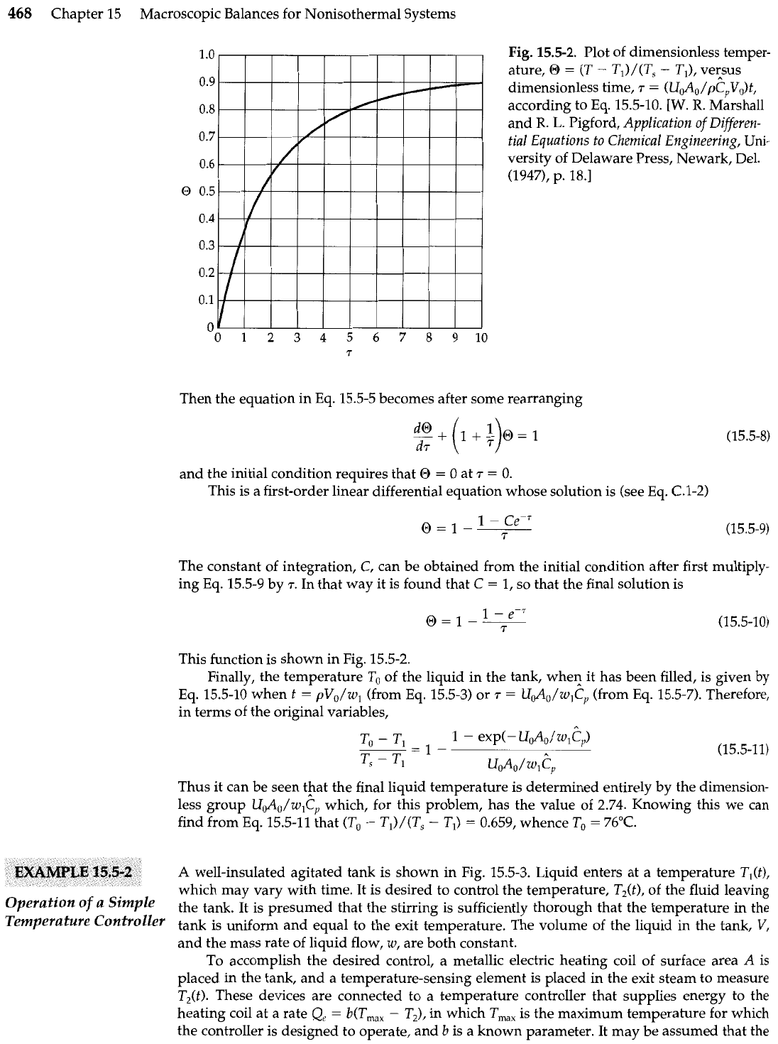
Fig.
15.5-2.
Plot of dimensionless temper-
ature,
O
=
(T
-
TJ/(T,
-
TI), vecsus
dimensionless time,
7
=
(UJ,/pC,V,)t,
according to Eq. 15.5-10.
[W.
R.
Marshall
and
R.
L.
Pigford, Application
of
Differen-
tial Equations to Chemical Engineering, Uni-
versity of Delaware Press, Newark, Del.
(1947), p. 18.1
Then the equation in Eq. 15.5-5 becomes after some rearranging
and the initial condition requires that
O
=
0 at
7
=
0.
This is a first-order linear differential equation whose solution is (see Eq. C.l-2)
The constant of integration, C, can be obtained from the initial condition after first multiply-
ing Eq. 15.5-9 by
r.
In that way it is found that C
=
1, so that the final solution is
This function is shown in Fig. 15.5-2.
Finally, the temperature To of the liquid in the tank, whe? it has been filled, is given by
Eq. 15.5-10 when t
=
pV,/wl (from Eq. 15.5-3) or
T
=
U&/w,C, (from Eq. 15.5-7). Therefore,
in terms of the original variables,
Thus it can be seen tpat the final liquid temperature is determined entirely by the dimension-
less group U&/wlCr which, for this problem, has the value of 2.74. Knowing this we can
find from Eq. 15.5-11 that (To
-
Tl)/(T,
-
T,)
=
0.659, whence
To
=
76°C.
A
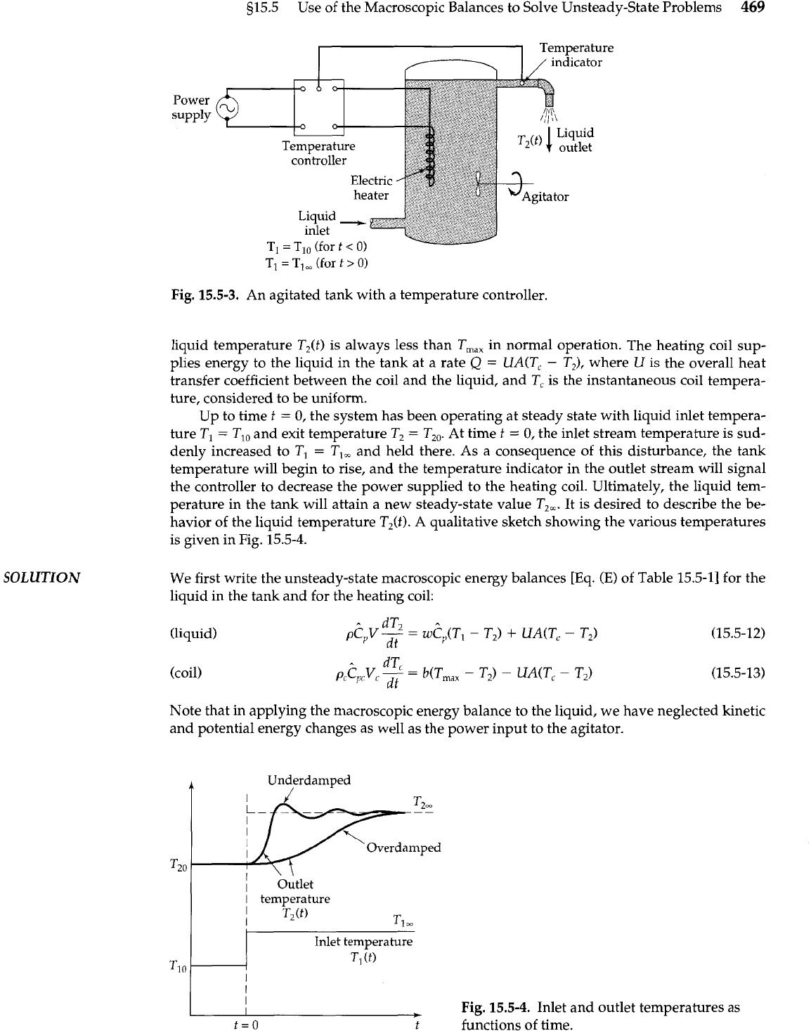
well-insulated agitated tank is shown in Fig. 15.5-3. Liquid enters at a temperature T,(t),
which may vary with time. It is desired to control the temperature, T,(t), of the fluid leaving
the tank. It is presumed that the stirring is sufficiently thorough that the temperature in the
tank is uniform and equal to the exit temperature. The volume of the liquid in the tank,
V,
and the mass rate of liquid flow,
w,
are both constant.
To accomplish the desired control, a metallic electric heating coil of surface area
A
is
placed in the tank, and a temperature-sensing element is placed in the exit steam to measure
TJt).
These devices are connected to a temperature controller that supplies energy to the
heating coil at a rate
Q,
=
b(T,,,
-
TJ, in which
T,,,
is the maximum temperature for which
the controller is designed to operate, and
b
is a known parameter. It may be assumed that the
s15.5
Use of the Macroscopic Balances to Solve Unsteady-State Problems
469
SOLUTION
Power
supply
Temperature
/
indicator
Temperature
controller
Electric
heater
Liquid
-
inlet
\
Liquid
outlet
-
--
TI
=
TI,
(for
t
>
0)
Fig.
15.5-3.
An agitated tank with
a
temperature controller.
liquid temperature T,(t) is always less than T,,, in normal operation. The heating coil sup-
plies energy to the liquid in the tank at a rate
Q
=
UA(T,
-
T2), where
U
is the overall heat
transfer coefficient between the coil and the liquid, and T, is the instantaneous coil tempera-
ture, considered to be uniform.
Up to time
t
=
0, the system has been operating at steady state with liquid inlet tempera-
ture TI
=
TI,
and exit temperature T,
=
T,,. At time
t
=
0, the inlet stream temperature is sud-
denly increased to
TI
=
T,,
and held there. As a consequence of this disturbance, the tank
temperature will begin to rise, and the temperature indicator in the outlet stream will signal
the controller to decrease the power supplied to the heating coil. Ultimately, the liquid tem-
perature in the tank will attain a new steady-state value Tz,. It is desired to describe the be-
havior of the liquid temperature
T2(f).
A
qualitative sketch showing the various temperatures
is given in Fig. 15.5-4.
We first write the unsteady-state macroscopic energy balances [Eq.
(E)
of Table 15.5-11 for the
liquid in the tank and for the heating coil:
(liquid)
(coil)
Note that in applying the macroscopic energy balance to the liquid, we have neglected kinetic
and potential energy changes as well as the power input to the agitator.
4
Underdamped
Overdamped
I
1
bitlet
I
temperature
I
T2(t)
I
TI
I
I
L
Fig. 15.5-4.
Inlet and outlet temperatures as
t=O
f
functions of time.
470
Chapter 15 Macroscopic Balances for Nonisothermal Systems
(a)
Steady-state behavior for t
<
0.
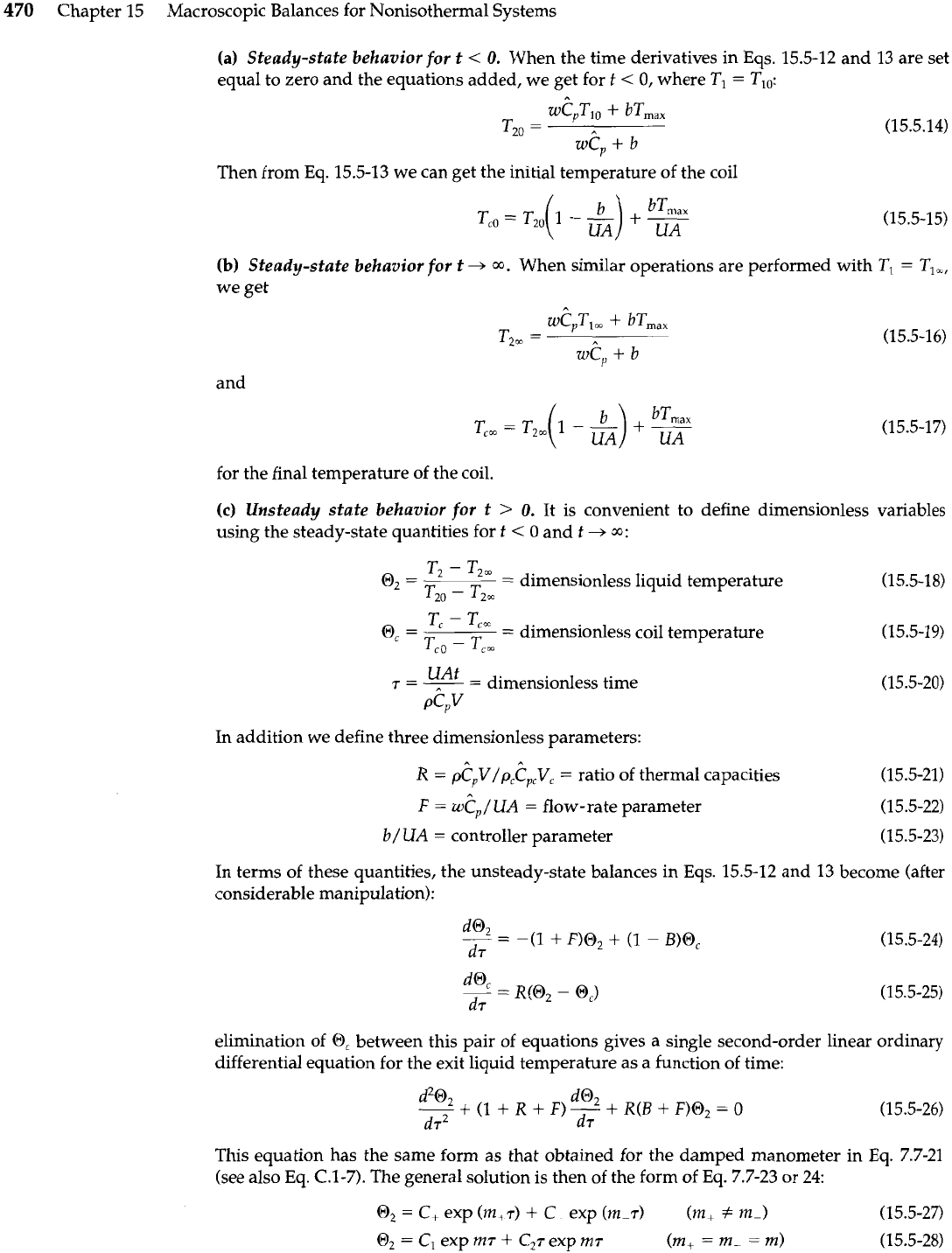
When the time derivatives in Eqs. 15.5-12 and 13 are set
equal to zero and the equations added, we get for
t
<
0, where TI
=
TI,:
Then from Eq. 15.5-13 we can get the initial temperature of the coil
(b)
Steady-state behavior for
t
+
m.
When similar operations are performed with TI
=
TI,,
we get
and
for the final temperature of the coil.
(c)
Unsteady state behavior for t
>
0.
It is convenient to define dimensionless variables
using the steady-state quantities for
t
<
0 and
t
+
m:
T2
-
T2m
O2
=
=
dimensionless liquid temperature (15.5-18)
T20
-
T20:
T'
-
T,,
0,
=
=
dimensionless coil temperature
Tc,
-
Tc,
UAt
r
=
,--
=
dimensionless time
PC,~
In addition we define three dimensionless parameters:
A
R
=
pC,V/p,Cp,Vc
=
ratio of thermal capacities
(15.5-21)
F
=
W~/UA
=
flow-rate parameter
(15.5-22)
b/
UA
=
controller parameter
(15.5-23)
In terms of these quantities, the unsteady-state balances in Eqs. 15.5-12 and 13 become (after
considerable manipulation):
elimination
of
0,
between this pair of equations gives a single second-order linear ordinary
differential equation for the exit liquid temperature as a function of time:
This equation has the same form as that obtained for the damped manometer in Eq. 7.7-21
(see also Eq.
C.1-7).
The general solution is then of the form of Eq. 7.7-23 or 24:
0,
=
C+ exp (m+r)
+
C exp (m-r)
(m+
+
m-)
(15.5-27)
0,
=
C, exp
rnr
+
C2r exp
rn~
(m,
=
m-
=
m)
(15.5-28)
g15.5 Use of the Macroscopic Balances to Solve Unsteady-State Problems
471
EXAMPLE
15.5-3
Flow
of
Compressible
Fluids
Through
Head
Meters
where
m,
=
$[-(I
+
R
+
F)
*
d(1
+
R
+
F)~
-
4R(B
+
F)]
(15.5-29)
Thus by analogy with Example 7.7-2, the fluid exit temperature may approach its final value
as a monotone increasing function (overdamped or critically damped) or with oscillations
(underdamped). The system parameters appear in the dimensionless time variable, as well as
in the parameters
B,
F,
and
R.
Therefore, numerical calculations are needed to determine
whether in a particular system the temperature will oscillate or not.
Extend the development of Example 7.6-5 to the steady flow of compressible fluids through
orifice meters and Venturi tubes.
SOLUTION
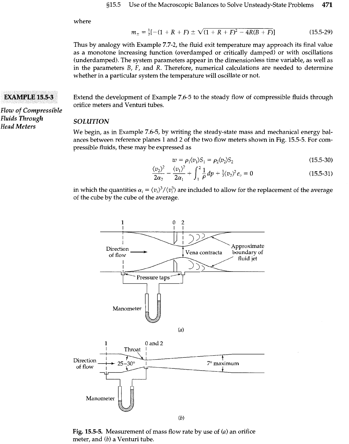
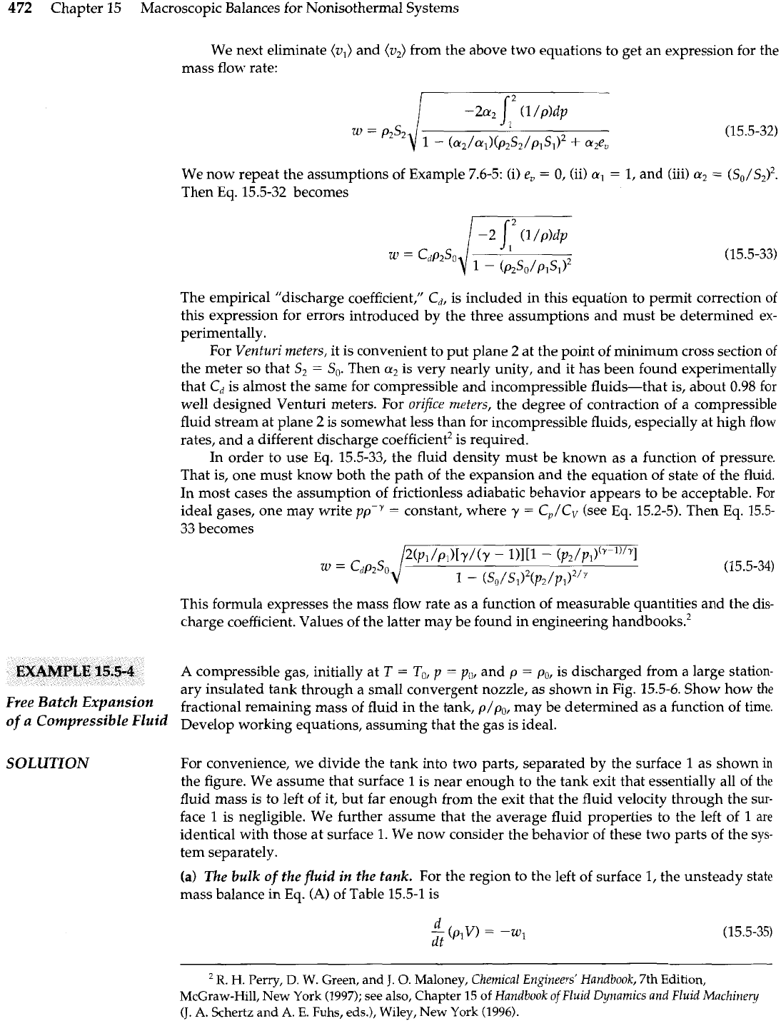
We begin, as in Example 7.6-5, by writing the steady-state mass and mechanical energy bal-
ances between reference planes 1 and
2
of the two flow meters shown in Fig. 15.5-5. For com-
pressible fluids, these may be expressed as
in which the quantities
ai
=
(v~)~/(v~)
are included to allow for the replacement of the average
of the cube by the cube of the average.
. .
Direction
-
of
flow
1
0
and
2
I
Throat
1
I
I
Direction
-
,*I
I
I.
7'
maximum
of
flow
I
J
Fig.
15.5-5.
Measurement of mass flow rate by use of
(a)
an orifice
meter, and
(b)
a Venturi tube.
472
Chapter 15 Macroscopic Balances for Nonisothermal Systems
We next eliminate (v,) and (v,) from the above two equations to get an expression for the
mass flow rate:
We now repeat the assumptions of Example 7.6-5: (i)
e,
=
0,
(ii)
a,
=
1, and (iii)
cr2
=
(so/s2)'.
Then
Eq.
15.5-32 becomes
The empirical "discharge coefficient," Cd, is included in this equation to permit correction of
this expression for errors introduced by the three assumptions and must be determined ex-
perimentally.
For
Venturi meters,
it is convenient to put plane 2 at the point of minimum cross section
of
the meter so that S2
=
So.
Then
a,
is very nearly unity, and it has been found experimentally
that Cd is almost the same for compressible and incompressible fluids-that is, about
0.98
for
well designed Venturi meters. For
orifice
meters,
the degree of contraction of a compressible
fluid stream at plane
2
is somewhat less than for incompressible fluids, especially at high flow
rates, and a different discharge coefficient2 is required.
In order to use
Eq.
15.5-33, the fluid density must be known as a function of pressure.
That is, one must know both the path of the expansion and the equation of state of the fluid.
In most cases the assumption of frictionless adiabatic behavior appears to be acceptable. For
ideal gases, one may write
ppP
=
constant, where
y
=
CJCV
(see Eq. 15.2-5). Then Eq. 15.5-
33 becomes
This formula expresses the mass flow rate as a function of measurable quantities and the dis-
charge coefficient. Values of the latter may be found in engineering
handbook^.^
A compressible gas, initially at
T
=
To,
p
=
p,,,
and p
=
po, is discharged from a large station-
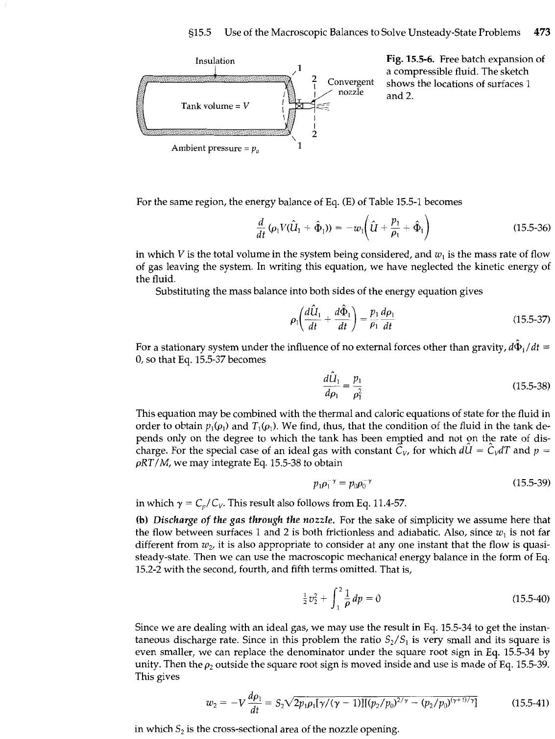
ary insulated tank through a small convergent nozzle, as shown in Fig. 15.5-6. Show how the
Free
Batch
fractional remaining mass of fluid in the tank, p/p,, may be determined as a function of time.
of
a
Compressible Fluid
Develop working equations, assuming that the gas is ideal.
SOLUTION
For convenience, we divide the tank into two parts, separated by the surface 1 as shown
in
the figure. We assume that surface 1 is near enough to the tank exit that essentially all of
the
fluid mass is to left of it, but far enough from the exit that the fluid velocity through the sur-
face
1
is negligible. We further assume that the average fluid properties to the left of
1
are
identical with those at surface
1.
We now consider the behavior of these two parts of the sys-
tem separately.
(a)
The
bulk
of
the
fluid
in the tank.
For the region to the left of surface 1, the unsteady state
mass balance in
Eq.
(A) of Table 15.5-1 is
R.
H.
Perry,
D. W.
Green, and
J.
0.
Maloney,
Chemical Engineers'
Handbook,
7th Edition,
McGraw-Hill, New York (1997); see also, Chapter
15
of
Handbook
of
Fluid Dynamics
and
Fluid
Machinery
(J.
A.
Schertz and
A.
E.
Fuhs, eds.), Wiley, New York (1996).
g15.5
Use of the Macroscopic Balances to Solve Unsteady-State Problems
473
Insulation
Fig.
15.5-6.
Free batch expansion of
Convergent
;,
nozzle
f'
1
Tank
volume
=
V
]
a ~ompressible fluid.
hes sketch
shows the locations of surfaces
1
and 2.
Ambient pressure
=
p,
1
For the same region, the energy balance of Eq. (E) of Table 15.5-1 becomes
in which
V
is the total volume in the system being considered, and w1 is the mass rate of flow
of gas leaving the system. In writing this equation, we have neglected the kinetic energy of
the fluid.
Substituting the mass balance into both sides of the energy equation gives
,.
For a stationary system under the influence of no external forces other than gravity,
d@,/dt
=
0, so that Eq. 15.5-37 becomes
This equation may be combined with the thermal and caloric equations of state for the fluid in
order to obtain pl(pl) and T,(p,). We find, thus, that the condition of the fluid in the tank de-
pends only on the degree to which the tank has been emptied and not on tte rate of dis-
charge. For the special case of an ideal gas with constant Cv, for which
dU
=
CdT and
p
=
pRT/M, we may integrate Eq. 15.5-38 to obtain
in which
y
=
CJC,.
This result also follows from
Eq.
11.4-57.
(b)
Discharge
of
the gas through the nozzle.
For the sake of simplicity we assume here that
the flow between surfaces 1 and 2 is both frictionless and adiabatic. Also, since
w,
is not far
different from w2, it is also appropriate to consider at any one instant that the flow is quasi-
steady-state. Then we can use the macroscopic mechanical energy balance in the form of
Eq.
15.2-2 with the second, fourth, and fifth terms omitted. That is,
Since we are dealing with an ideal gas, we may use the result in
Eq.
15.5-34 to get the instan-
taneous discharge rate. Since in this problem the ratio S2/S1 is very small and its square is
even smaller, we can replace the denominator under the square root sign in Eq. 15.5-34 by
unity. Then the p2 outside the square root sign is moved inside and use is made of Eq. 15.5-39.
This gives
in which S2 is the cross-sectional area of the nozzle opening.
474
Chapter
15
Macroscopic Balances for Nonisothermal Systems
PROBLEMS
1s~~.
Now we use Eq.
15.5-39
to eliminate
p,
from Eq.
15.5-41.
Then we have a first-order dif-
ferential equation for
p,,
which may be integrated to give
From this equation we can obtain the time required to discharge any given fraction of
the
original gas.
At low flow rates the pressure
p2
at the nozzle opening is equal to the ambient pressure.
However, examination of
Eq.
15.5-41
shows that, as the ambient pressure is reduced, the
cal-
culated mass rate of flow reaches a maximum at a critical pressure ratio
For air
(y
=
1.4),
this critical pressure ratio is
0.53.
If the ambient pressure is further reduced,
the pressure just inside the nozzle will remain at the value of
p2
calculated from Eq.
15.5-43,
and the mass rate of flow will become independent of ambient pressure
p,.
Under these con-
ditions, the discharge rate is
Then, for
pJp,
<
r, we may write Eq.
15.5-42
more simply:
If
p,/pl
is initially less than
r,
both Eqs.
15.5-46
and
42
will be useful for calculating the total
discharge time.
QUESTIONS FOR DISCUSSION
Give the physical significance of each term in the five macroscopic balances.
How are the equations of change related to the macroscopic balances?
Does each of the four terms within the parentheses in Eq.
15.1-2
represent a form of energy?
Explain.
How is the macroscopic (total) energy balance related to the first
law
of thermodynamics,
AU
=
Q+
w?
Explain how the averages
(v)
and
(v3)
arise in Eq.
15.1-1.
What is the physical significance of
E,
and
E,?
What sign do they have? How are they related
to the velocity distribution? How can they be estimated?
How is the macroscopic balance for internal energy derived?
What information can be obtained from Eq.
15.2-2
about a fluid at rest?
Heat transfer
in
double-pipe heat exchangers.
(a) Hot oil entering the heat exchanger in Example
15.4-1
at surface
2
is to be cooled by water
entering at surface
1.
That
is,
the exchanger is being operated in countercurrent flow. Compute
the required exchanger area
A,
if the heat transfer coefficient
U
is
200
Btu/hr. ft2
.
F
and the
fluid streams have the following properties:
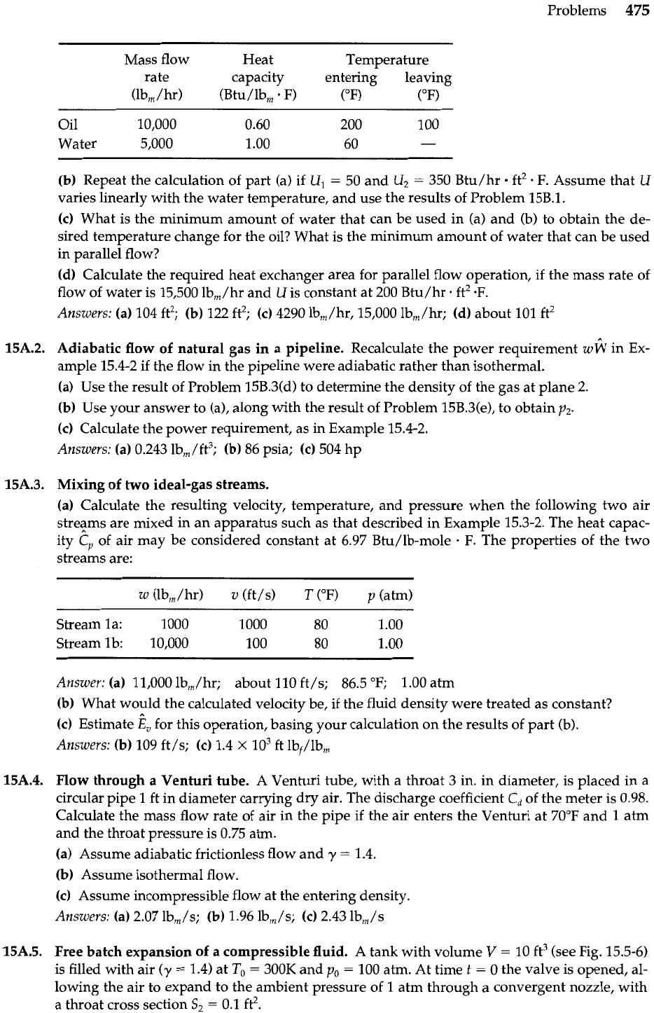
Problems
475
Mass flow Heat Temperature
rate capacity entering leaving
(lbm
/
hr) (Btu/lb,
.
F) (OF) (OF)
Oil 10,000
0.60 200 100
Water 5,000
1
.OO
60
-
(b)
Repeat the calculation of part (a) if U,
=
50 and U2
=
350 Btu/hr ft2 F. Assume that
U
varies linearly with the water temperature, and use the results of Problem 15B.1.
(c)
What is the minimum amount of water that can be used in (a) and (b) to obtain the de-
sired temperature change for the oil? What is the minimum amount of water that can be used
in parallel flow?
(dl
Calculate the required heat exchanger area for parallel flow operation, if the mass rate of
flow of water is 15,500 Ib,/hr and U is constant at 200 Btu/hr. ft2
SF.
Answers:
(a)
104 ft2;
(b)
122 ft2;
(c)
4290 lbm/hr, 15,000 lb,/hr;
(d)
about 101 ft2
15A.2. Adiabatic flow of natural gas in
a
pipeline.
Recalculate the power requirement
wlk
in Ex-
ample 15.4-2 if the flow in the pipeline were adiabatic rather than isothermal.
(a)
Use the result of Problem 15B.3(d) to determine the density of the gas at plane 2.
(b)
Use your answer to (a), along with the result of Problem 15B.3(e), to obtain p2.
(c)
Calculate the power requirement, as in Example 15.4-2.
Answers:
(a)
0.243 lb,/ft3;
(b)
86 psia;
(c)
504 hp
15A.3. Mixing of two ideal-gas streams.
(a)
Calculate the resulting velocity, temperature, and pressure when the following two air
streams are mixed in an apparatus such as that described in Example 15.3-2. The heat capac-
ity
C,
of air may be considered constant at 6.97 Btu/lb-mole
.
F.
The properties of the two
streams are:
Stream la: 1000
1000 80
1
.OO
Stream lb: 10,000
100 80 1 .OO
Answer:
(a)
11,000 Ib,/hr; about 110 ft/s; 86.5 OF; 1.00 atrn
(b)
What would the calculated velocity be, if the fluid density were treated as constant?
(c)
Estimate
k,
for this operation, basing your calculation on the results of part (b).
Answers:
(b)
109 ft/s;
(c)
1.4
X
lo3
ft Ibf/lb,
15A.4. Flow through
a
Venturi tube.
A
Venturi tube, with a throat
3
in. in diameter, is placed in a
circular pipe
1
ft in diameter carrying dry air. The discharge coefficient
Cd
of the meter is 0.98.
Calculate the mass flow rate of air in the pipe if the air enters the Venturi at 70°F and 1 atrn
and the throat pressure is 0.75 atm.
(a)
Assume adiabatic frictionless flow and y
=
1.4.
(b)
Assume isothermal flow.
(c)
Assume incompressible flow at the entering density.
Answers:
(a)
2.07 lb,/s;
(b)
1.96 lbm/s;
(c)
2.43 lbm/s
15A.5. Free batch expansion of a compressible fluid.
A
tank with volume
V
=
10 ft3 (see Fig. 15.5-6)
is filled with air (y
=
1.4) at
To
=
300K and
po
=
100 atm. At time
t
=
0 the valve is opened, al-
lowing the air to expand to the ambient pressure of 1 atrn through a convergent nozzle, with
a throat cross section S2
=
0.1 ft2.
476
Chapter 15 Macroscopic Balances for Nonisothermal Systems
(a) Calculate the pressure and temperature at the throat of the nozzle, just after the start of
the discharge.
(b)
Calculate the pressure and temperature within the tank when p2 attains its final value of 1
atm.
(c)
How long will it take for the system to attain the state described in
(b)?
Heating of air in a tube.
A
horizontal tube of 20 ft length is heated by means of an electrical
heating element wrapped uniformly around it.
Dry
air enters at 5'F and 40 psia at a velocity
75 ft/s and 185 lb,/hr. The heating element provides heat at a rate of 800 Btu/hr per foot of
tube. At what temperature will the air leave the tube, if the exit pressure is 15 psia? Assume
turbulent flow and ideal gas behavior. For air in the range of interest the heat capacity at con-
stant pressure in Btu/lb-mole
.
F is
where
T
is expressed in degrees Rankine.
Answer:
T,
=
354°F
Operation of a simple double-pipe heat exchanger.
A
cold-water stream, 5400 lb,,/hr at
70°F, is to be heated by 8100 lb,,/hr of hot water at 200°F in a simple double-pipe heat ex-
changer. The cold water is to flow through the inner pipe, and the hot water through the an-
nular space between the pipes. Two 20-ft lengths of heat exchanger are available, and also all
the necessary fittings.
(a) By means of a sketch, show the way in which the two double-pipe heat exchangers should
be connected in order to get the most effective heat transfer.
(b) Calculate the exit temperature of the cold stream for the arrangement decided on in (a)
for the following situation:
(i) The heat-transfer coefficient for the annulus, based on the heat transfer area of the
inner surface of the inner pipe is 2000 Btu/hr. ft2. F.
(ii) The inner pipe has the following properties: total length, 40 ft; inside diameter 0.0875
ft; heat transfer surface per foot, 0.2745 ft2; capacity at average velocity of
1
ft/s is 1345 lb,/hr.
(iii) The average properties of the water in the inner pipe are:
(iv) The combined resistance of the pipe wall and encrustations is 0.001 hr
.
ft2
.
F/Btu
based on the inner pipe surface area.
(c)
Sketch the temperature profile in the exchanger.
Answer:
(b)
136°F
Performance of
a
double-pipe heat exchanger with variable overall heat transfer coeffi-
cient. Develop an expression for the amount of heat transferred in an exchanger of the type
discussed in Example 15.4-1, if the overall heat transfer coefficient
U
varies linearly with the
temperature of either stream.
(a)
Since
Th
-
T,
is a linear function of both
Th
and
T,,
show that
U-U,
-
AT-AT,
-
U2
-
U,
AT2
-
ATl
in which
AT
=
Th
-
T,,
and the subscripts
1
and
2
refer to the conditions at control surfaces 1
and 2.
