Awrejcewicz J. Numerical Simulations of Physical and Engineering Processes
Подождите немного. Документ загружается.


The Static and Dynamic Transfer-Matrix Methods in the Analysis of Distributed-Feedback Lasers
453
and for the central zone. For the whole laser description five cells are needed: two cells for
the facets, two cells for the outer zones in the corrugation and one cell for the central zone.
The second CPM laser corresponds to a linear chirp corrugation, that is, a structure with a
continuous change in the corrugation period.
3.2 Above-threshold analysis
In the above-threshold regime,
()
Sz assumes high enough values to induce important non-
uniformities in
()
Nz
and
()
nz . Despite the SHB effect might be minimized by an adequate
design of the DFB structure, the interdependence of
() ()
,Sz Nz and
()
nz can’t be neglected
anymore. Therefore, in order to insure a correct evaluation of the above-threshold
characteristics, each section shall be divided into several sub-sections. According to
(Ghafouri-Shiraz, 2003), for a 500 μm cavity length, about 5000 cells should be considered in
order to ensure a reasonable accuracy in the stationary analysis.
The above-threshold calculations follow closely the method described in (Fessant, 1997;
Ghafouri-Shiraz, 2003). However, in order to ensure a quick convergence in the evaluations
of the laser characteristics, an adequate strategy is proposed.
3.2.1 Lasing-mode analysis
For each bias current I, the numerical above-threshold analysis concerning the lasing-mode
is summarized as follows
a.
Successive
()
GG×
grids are created in the
()
0
,c λ
plane. The i-th grid is centered at
()
()
()
0
,
c
i
i
c
c λ and it is enclosed in the region defined by the limits
min max
() () ()
min
00
,,
ii i
ccλ and
()
max
.
i
λ
For the initial grid
()
1i =
3
(1)
cth
λ=λ
(85)
()
() ()
()
(1)
0
22
/2
0
2
00
0
c
RS
hc I I q V v g n n
hc I I
th act g th th g th
th
c
qV v g n n
EE
act
g
th th
g
th
−ελ
−
==
ελ
+
(86)
min max
(1) (1) (1) (1) (1) (1)
00
00 00
(1)
(1) (1) (1) (1) (1)
max
min
;
;.
cc
cc
ccc ccc=−Δ =+Δ
λ = λ − Δλ λ = λ + Δλ
(87)
For
(1) (1)
0
0
10, /10
c
GccΔ
and
(1)
0.1 nmΔλ
seem adequate for most of DFB laser
structures. However, a readjustment of
(1)
0
cΔ and
(1)
Δλ may, occasionally, be necessary in
order to prevent an eventual convergence towards a local minimum. This is a critical aspect of
the proposed analysis, since an inadequate choice would prevent the numerical convergence.
b.
For each one of the
2
G pairs of the i-th grid,
()
(1) (1)
0
,
k
l
c λ with ;1...,kl G= equations (79-
82) are self-consistently solved in order to determine the material gain, the carrier
3
In (86) it has been taken into account the normalization condition (83).

Numerical Simulations of Physical and Engineering Processes
454
density, the photon density and the effective index for each one of the j-th sub-section,
respectively, , ,
jjj
g
NS and ,
j
n
with 1.jM≤≤
c.
Equations (78) are solved in order to determine the lasing-mode gain and detuning for
the j-th sub-section, respectively,
j
α
and
.
j
δ
The transfer matrix of the j-th sub-section
,
()
1
T/
jj
zz
+
is then calculated.
d.
Using the TMM , the two counter-running waves at the output of the j-th sub-section,
j
R
E and ,
j
S
E are obtained. For the M-th sub-section the discrepancy found between
those values and the laser right facet boundary condition is represented by
()
.
i
kl
ε This
value is evaluated and stored for each pair
()
() ()
0
,
k
ii
l
c λ of the i-th grid. The error
associated to the i-th grid is given by
()
()
()
min .
i
i
kl
ε= ε
e.
Whenever
() ( 1)
,
ii−
ε=ε the central pair remains the same
()
(1) ()
(1) ()
00
,,
cc
ii
ii
cc
cc
+
+
=λ=λbut
new limits are required for the next grid description. The partitions should be reduced
considering, for instance:
(1) ()
00
/10
ii
cc
+
Δ=Δ and
(1) ()
/10.
ii+
Δλ = Δλ Whenever
() ( 1)
,
ii−
ε<ε the pair associated with
()
()
min
i
kl
ε is chosen as the next central pair
()
(1)
(1)
0
,,
c
i
i
c
c
+
+
λ
while
0
c
and λ partitions remain unchangeable. For
(1)
1,
i
i
−
=ε is taken
as the error associated with the central pair
()
(1)
(1)
0
,.
c
c
c λ
For each one of the
2
G pairs
()
(1) (1)
0
,,
k
ii
l
c
++
λ the steps a)-e) are repeated until
(1)
min
,
i+
ε<ε
where
min
ε is a preset error value, for instance, less than
14
10
−
(Ghafouri-Shiraz, 2003).
Since the gain
j
α and the detuning
j
δ are z-dependent, the lasing characteristics for each
bias current are associated with their mean values along the cavity, given by
() () () ()
11
11
;.
MM
av j av j
jj
IIII
MM
==
α= α δ= δ
(88)
Notice that the sequential analysis a) to e) assumes a one-mode propagation laser behavior.
This procedure is itself a good assumption, since the present analysis focus on DFB
structures that must guarantee SLM operation. Otherwise, different strategies should be
adopted.
Finally, when studying the influence of the bias current on the laser characteristics, a
considerable CPU time reduction can be achieved if, for each subsequent current, instead of
using (85),
(1)
c
λ
is taken as the solution found for the previous bias current.
3.2.2 Side-mode analysis
() ()
,Sz Nz
and
()
nz
profiles are settled for each bias current by the lasing-mode profiles
obtained in section 3.2.1. At threshold, theses distributions are nearly uniform along the
cavity, assuming average values, respectively, 0,
th
N and .
th
n The gain mode and detuning

The Static and Dynamic Transfer-Matrix Methods in the Analysis of Distributed-Feedback Lasers
455
associated with the side-mode at threshold, respectively,
side
α and
1
,δ are settled. In the
one-mode approximation, the use of (79) leads to
()
()
1
1
2
,
2
Bth g
R
g
av
nn
n
Λ
Λ
πλ +
λδ=
πλ
δλ + π +
Λ
(89)
where
av
Λ is the average grating period given by
1
.
M
mm
m
av
L
L
=
⋅Λ
Λ=
(90)
This assumption means that
()
1R
λδ would be the threshold wavelength if
1
δ would
correspond to the lasing mode. On the other hand, regarding the side-mode gain, (78)
imposes that
side 1 loss
2,gα=Γ−α
(91)
where
1
g is obtained from (82) , making
()
th
Nz N= and
()
1side
.λ=λ α
The parameter
()
1side
λα
should be interpreted as the wavelength in the one-mode approach if
side
α would
correspond to the threshold gain. It will be designated by the side-mode effective wavelength.
Similarly, for the lasing mode, it is obtained
loss
2,
th th
gα=Γ −α
(92)
where
()
00
.
th th
gANN=− Then, from (91) and (92), it can be shown that
() ()()
()
side
1 side side side
1
2
;.
th
th I I
j
A
α−α
λα =λ+λα λα =
Γ
(93)
A
()
GG×
grid is created in the plane
()
,,
IR
λλ
adopting a similar procedure as the one
described in Section 3.2.1 for the plane
()
0
,.c λ
The initial grid is centered in
()
(1) (1)
,,
cc
IR
λλ
where
(1)
c
I
λ
and
(1)
c
R
λ
are given, respectively, by the second equation (93) and (89). The limits
of the initial grid are defined by
(1) (1)
c
I
I
λ±Δλand
(1) (1)
.
c
R
R
λ±Δλ The values
(1)
10, 0.01 nm
I
G =Δλ and
(1)
0.1 nm
R
Δλ seem reasonable for most of the structures but,
as previously referred, a readjustment may once in a while be necessary to avoid the mode
hopping. Usually
(1)
I
Δλ is one order of magnitude lower than
(1)
R
Δλ because the difference
between the normalized gains for different modes is about one order of magnitude lower
than the difference between their normalized detunings.
Successive
()
GG×
grids are defined in the wavelength plane, centering the i-th grid in
()
() ()
,,
cc
ii
IR
λλ and enclosing it in the region defined by the limits
() ()
c
ii
I
I
λ±Δλ and
() ()
.
c
ii
R
R
λ±Δλ

Numerical Simulations of Physical and Engineering Processes
456
Then, for each bias current and pair
()
,kl of the i-th grid, i.e.
()
() ()
,,
kl
ii
II
λλ the mode gain and
detuning for each one of the
()
1,....
jj
M= sub-sections of the cavity are obtained as,
respectively
()
()
()
()
2
() () () ()
1
side side
() ()
2
2
;.
2
kl k kl l
jj
ll
g
iii i
jjB
IR
ii
j
RR
n
A
InI
Λ
π
Γπ π
α=α+λ δ= − λ−λ+
Λ
λλλ
(95)
In (95)
()
j
Iα and
()
j
nI are, respectively, the lasing-mode gain and the refractive index
associated with the j-th subsection for a biasing current I achieved in Section 3.2.1. Besides,
j
Λ is the corrugation period of the j-th subsection. Similarly as in Section 3.2.1, steps c)-e)
are the sequentially followed. However, the side-mode analysis is quicker than the lasing
mode analysis since the step b) is not implemented.
4. The dynamic TMM
In its conventional form, the transfer matrix
()
1
T
mm
zz
+
of a given cell inside the laser
cavity expresses the relationship described by (58). In this formulation, a steady-state
operation has implicitly been assumed. It is now required to develop a time-dependent
implementation of the TMM. As far as the dynamic-TMM is concerned, the increment of
time requires updating the travelling-wave amplitudes as they pass through a section. The
increment tΔ is chosen so that the spatial step size, ,lΔ is given by the product of the time
increment by the group velocity
()
.
g
ltvΔ=Δ× So, after one increment tΔ , the backward
wave
1
(,)
Sm
Ez t
+
travels one section to the left, becoming (, ),
Sm
Ez t t+Δ and the forward
wave
(,)
Rm
Ez ttravels one section to the right, being then designated by
1
(, ).
Rm
Ez t t
+
+Δ
Assuming that the transfer matrix remains unchanged during the time step, it yields after
some simple manipulation of (58) (Lee et al., 1999) that
()
()() ()() ()
()
1
11 22 12 21 12
1
22
21
(, ) (,)
1
.
(, ) ( ,)
1
mm mm m
Rm Rm
m
m
Sm Sm
Ez t t t t t t t Ez t
Ez t t Ez t
t
t
+
+
+Δ −
=×
+Δ
−
(96)
Equation (96) forms the basis of the dynamic TMM, where it is assumed that the variations
in
()
1
T
mm
zz
+
and in the wave amplitudes occur in a time scale negligible in comparison
with the optical frequency. In a multi-electrode DFB model the local variations in carrier,
photon and refractive index are taken into account by further dividing the separately
pumped sections into subsections each one described by its own matrix
()
1
T
mm
zz
+
(Davis
& O’Dowd, 1991, 1992). Obviously, accuracy increases with the number of cells, but it
should always be kept in mind that the time computation increases almost quadratically
with the number of cells: increasing M decreases the step size lΔ and, simultaneously, the
time increment .tΔ
Dynamic-TMM analysis reinforces the relevance of the questions related to the need of
decreasing the heavy simulation times arising from the intensive search for those laser
parameters that complies with the boundary conditions of the problem under analysis. For
The Static and Dynamic Transfer-Matrix Methods in the Analysis of Distributed-Feedback Lasers
457
typical lengths of hundred of micrometers and data rate less than about 40 Gb/s, simulation
analysis requires no more than 100M = sections to guarantee enough method accuracy (Jia,
X. et al., 2007). The model solves self-consistently the carrier and photon rate equations
similarly as described in Section 3.1.
5. Simulation results and discussions
As an application example of the TMM it has been chosen a multiple phase-shift DFB laser
structure especially designed to provide SLM operation.
5.1 The laser structure
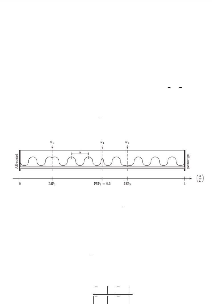
The laser structure is represented in Fig. 5. It is a multi-section AR-coated DFB laser with
uniform grating period
()
m
Λ=Λ and uniform coupling coefficient
()
.
m
κ=κ Three PS
discontinuities
()
i
ϕ
are located along the DFB laser structure. Their positions are represented
by a normalized parameter given by
PSP 1,2,3,
i
i
z
L
i==
(97)
where
i
z
is the
i
ϕ
position.
Fig. 5. A simplified schematic diagram of the 3PS-DFB laser structure with non-equal and
non-identical 3PS.
A purely index-coupled laser structure assures that
κ
is real. For the structure, it has been
assumed
500 m,L=μ
1
227,039nm, 0 radΛ= Ω = and
2
PSP 0.5.= Two important laser
figures of merit in the area of OCS are the normalized mode selectivity
σ
and the flatness of
the electric field distribution along the cavity ℑ , which are given by
()
2
0
;
1
,
th
L
av
LL
zdz
L
σ=α⋅ −α ⋅
ℑ= Ι−Ι
(98)
where
()
z
Ι
is the normalized electric field intensity at an arbitrary position z, which is given
by
()
() ()
() ()
22
22
00
RS
RS
Ez Ez
z
EE
+
Ι=
+
(99)

Numerical Simulations of Physical and Engineering Processes
458
and
av
Ι is its average value along the cavity. Notice that according to the normalization
condition (83),
()
zΙ is numerically equal to
() ()
22
.
RS
Ez Ez+ For laser structures with
500 mL =
μ
it is generally accepted (Ghafouri-Shiraz, 2003) that a stable SLM operation
requires
0.25σ≥ and 0.05.ℑ≤ The laser structural and material parameters used in the
simulations are summarized in Table 3.
Laser parameter Value Laser parameter Value
Material Parameters Structural parameters
Spontaneous emission rate,
A
81
2.5 10 s
−
×
Active layer width, w
1.5 m
μ
Bimolecular recombination
coefficient,
B
16 3 1
1.0 10 m s
−−
×
Active layer thickness,
d
0.12 m
μ
Auger recombination
coefficient, C
41 6 1
3.0 10 m s
−−
×
Cavity length,
L
500 m
μ
Differential gain,
0
A
20 2
2.7 10 m
−
×
Optical confinement
factor, Γ
0.35
Gain curvature,
1
A
19 3
1.5 10 m
−
×
Grating period,
Λ
227.039 nm
Differential peak wavelength,
2
A
32 4
2.7 10 m
−
×
Internal loss,
loss
α
31
4.0 10 m
−
×
Effective index at zero
injection,
0
n
3.41351524
Carrier density at
transparency,
0
N
24 3
1.23 10 m
−
×
Differential index, /dn dN
26 3
1.8 10 m
−
−×
Group velocity,
g
v
71
8.33 10 m×s
−
×
Nonlinear gain coefficient,
g
ε
23 3
1.5 10 m
−
×
Table 3. Summary of laser parameters.
5.2 The structure optimization (threshold situation)
The objective is twofold: to maximize
σ
and to minimize ℑ
at threshold. For this purpose,
it will be varied, simultaneously and independently, the following set of variables (decision
variables):
2113
,,PSP,,PSPLκϕ ϕ and
3
.
ϕ
The procedure initializes with the boundary
values that insure a stable SLM operation according to the selection criteria previously
referred, i.e.,
min
0.25σ=σ =
and
max
0.05.ℑ= ℑ = After each step, these values are adjusted
by fixing tighter limits, i.e., higher
σ
and smaller .ℑ The starting point is a AR QWS-DFB
laser structure
4
()
12 3
0, 90º , 0ϕ= ϕ= ϕ=
with
2.Lκ= In the specialized literature these
4
This phase change corresponds to a quarter wavelength shift and so, the name single λ/4-shifted DFB
also used.
The Static and Dynamic Transfer-Matrix Methods in the Analysis of Distributed-Feedback Lasers
459
lasers are often associated with high mode selectivity, zero frequency and small current
density at threshold. Nevertheless, the highly non-uniform electric field distribution induces
local carrier depletion near the centre of the cavity that is responsible for the degradation of
the laser performance in the high power regime. In the procedure adopted hereby it will
always be assumed that
12
PSP PSP≤ and
23
PSP PSP .≤ The step-by-step procedure can be
summarized as follows
Step 1.
One PS,
()
1
,
ϕ
is added in the first half of the cavity. The optimization of
()
11
PSP ,σ
ϕ
and
()
11
PSP ,ℑ
ϕ
is performed by varying simultaneously and
independently both arguments in their ranges:
1
0PSP 0.5≤≤ and
1
0º 180º.≤ϕ ≤ It
will be assumed as selection criteria that
()
11 min
PSP ,σϕ≥σand
()
11 max
PSP , .ℑϕ≤ℑ This procedure will lead to the definition of a region in the
()
11
PSP ,
ϕ
plane from which a solution is chosen and new boundaries
()
min max
,σℑ
are settled;
Step 2.
For the new boundaries, another PS,
()
3
,
ϕ
is placed in the second half of the cavity.
A similar procedure as the one described in step 1 is adopted, now for
()
33
PSP ,σ
ϕ
and
()
33
PSP , ,ℑϕassuming
3
0.5 PSP 1≤≤ and
3
0º 180º.≤ϕ ≤
Steps 1 and 2 are sequentially repeated until no improvements on
σ and ℑ are achieved.
The optima values for the set
()
11 33
PSP , ,PSP ,
ϕϕ
are found, assuming
2Lκ= and
2
90º.ϕ=
New optima boundaries
()
min max
,σℑ
are settled.
Step 3.
An optimization of
()
2
,Lσκ ϕ
and
()
2
,Lℑκ ϕ
is performed by varying
simultaneously and independently both arguments in their ranges:
13L≤κ ≤ and
2
0º 180º.≤ϕ ≤ It will be assumed as selection criteria that
()
2min
,Lσκ ϕ ≥σ
and
()
2max
,.Lℑκ ϕ ≤ℑ
Steps 1, 2 and 3 are repeated until no improvements on
σ
and ℑ are achieved. This means
that the best 3PS-DFB laser structure
()
11 2 2 33
PSP , ,PSP 0.5, 90º,PSP , , Lϕ=ϕ= ϕκ
is obtained,
as far as σ and
ℑ
are concerned. In all steps, and whenever necessary, an argument based
on the smallest threshold gain is used in order to decide the best solution.
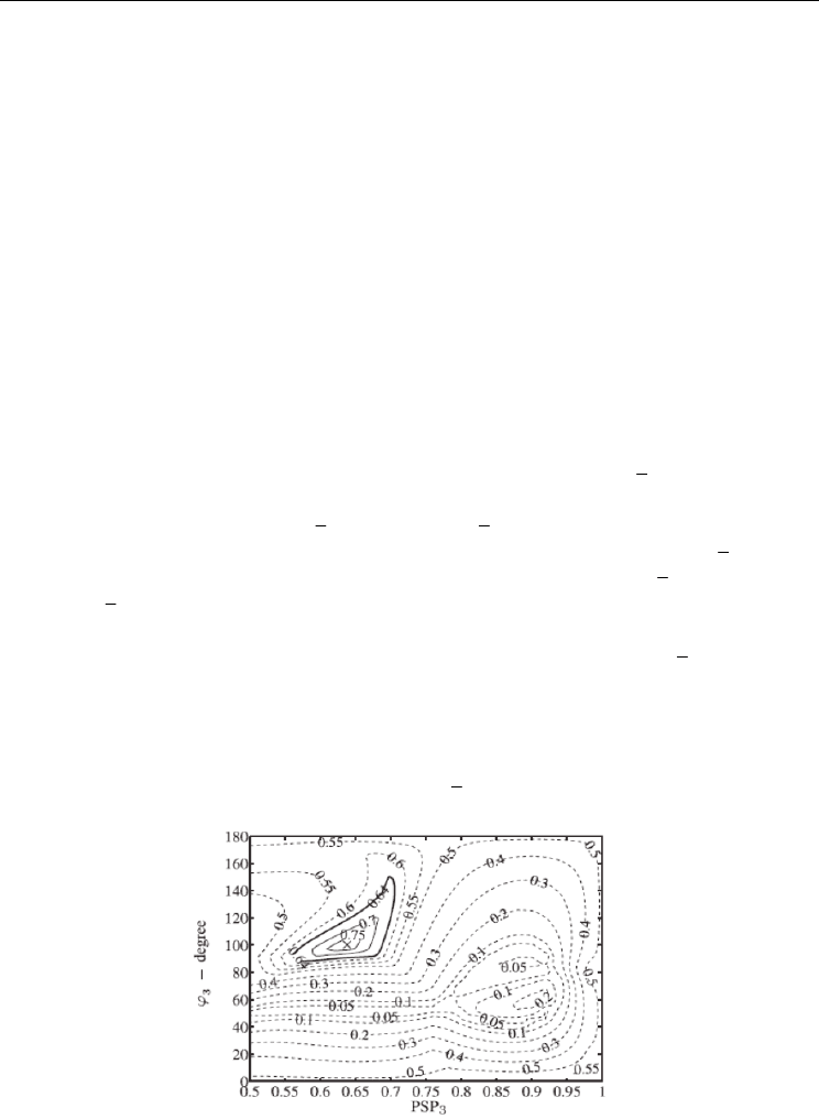
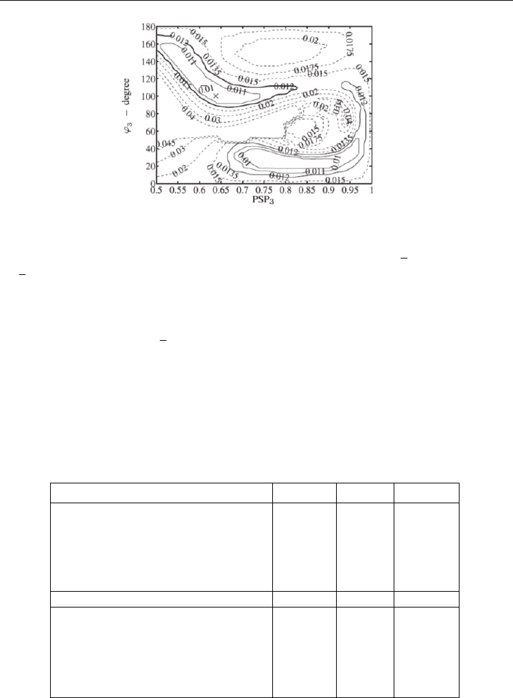
Fig.6 and Fig.7 show, respectively, the contour maps for
()
33
PSP ,σϕ
and
()
33
PSP , ,ℑϕ
when the arguments vary along their entire range, assuming
11 22
PSP 0.127, 110.7º , PSP 0.5, 60º
=ϕ= =ϕ=
and 1.7.L
κ=
Fig. 6. Contour maps of the mode selectivity in the
()
33
PSP , ϕ
plane. Values for
0.64σ≥
are
represented by solid lines.
Numerical Simulations of Physical and Engineering Processes
460
Fig. 7. Contour maps of the flatness in the
()
33
PSP , ϕ
plane. Values for 0.012ℑ≤ are
represented by solid lines.
Solid lines enclose all combinations
()
33
PSP , ϕ that ensure
()
2
,0.64Lσκ ϕ ≥
and
()
2
, 0.012,Lℑκ ϕ ≤ since
min
0.64σ=
and
max
0.012ℑ=
have been settled in the previous
iteration. Within all the possibilities, the chosen solution,
()
,× is
()
33
PSP 0.64, 100º ,=ϕ=
which corresponds to
min
0.78σ=
and
max
0.010.ℑ=
At the end of the optimization process,
the final solution has been found:
1
PSP 0.127,=
12
110.7º , PSP 0.5,ϕ= =
2
60º ,ϕ=
32
PSP 0.64, 100º=ϕ=
and
1.7.
L
κ= Besides, the optimized laser structure presents
1.18,
th
α=
which corresponds to
23.4mA.
th
I =
This value is similar to those reported in
(Ghafouri-Shiraz, 2003) for the QWS-DFB and the symmetric 3PS-DFB lasers, respectively,
19.8mA
th
I =
and
21.8mA.
th
I =
Table 4 summarizes the results for
,σℑ
and
th
Lα
achieved for three different laser
structures: the optimized 3PS-DFB (asymmetric), the QWS-DFB and the symmetric 3PS-DFB
referred in (Ghafouri-Shiraz, 2003). All lasers are AR-type because the random corrugation
phases at the laser facets will cause extra difficulty in controlling the laser characteristics.
Laser structure
σ
ℑ
th
Lα
Asymmetric 3PS-DFB (optimized)
11
22
33
PSP 0.127; 110.7º
PSP 0.500; 60º
PSP 0.640; 100º
=
ϕ
=
=ϕ=
=ϕ=
0.78
0.010
1.18
QWS-DFB 0.73 0.30 0.70
3PS-DFB (Ghafouri-Shiraz, 2003)
11
22
33
PSP 0.25; 60º
PSP 0.50; 60º
PSP 0.75; 60º
=ϕ=
=ϕ=
=ϕ=
0.34
0.012
0.78
Table 4. Figures of merit for the symmetric, asymmetric 3PS-DFB and QWS-DFB laser
structures.
The Static and Dynamic Transfer-Matrix Methods in the Analysis of Distributed-Feedback Lasers
461
As far as the flatness is concerned, the 3PS-DFB laser structures are clearly advantageous.
This is not surprising, since the inclusion of several PS along the laser cavity flattens the
field distribution. However, it is worth noticing that the asymmetric 3PS-DFB structure
reaches higher mode selectivity than the other two laser structures.
A threshold analysis has been presented. Nevertheless, one should always bear in mind that
the results for a structure presenting an adequate performance at threshold are not
conclusive. An above-threshold analysis is essential in order to assess the rate at which the
SHB effect deteriorates the laser features with the increasing current.
5.3 The above-threshold analysis
We shall begin with the stationary analysis, but, as we shall refer later, the transient aspects
may be determinant, which in fact imposes the need of a dynamic analysis in order to
describe adequately the laser performance in the domain of high currents. Both analysis will
lead to heavier simulations than the threshold analysis, since the number of cells needed for
a correct evaluation of the carrier and photon profiles is deeply increased.
5.3.1 The static-TMM results
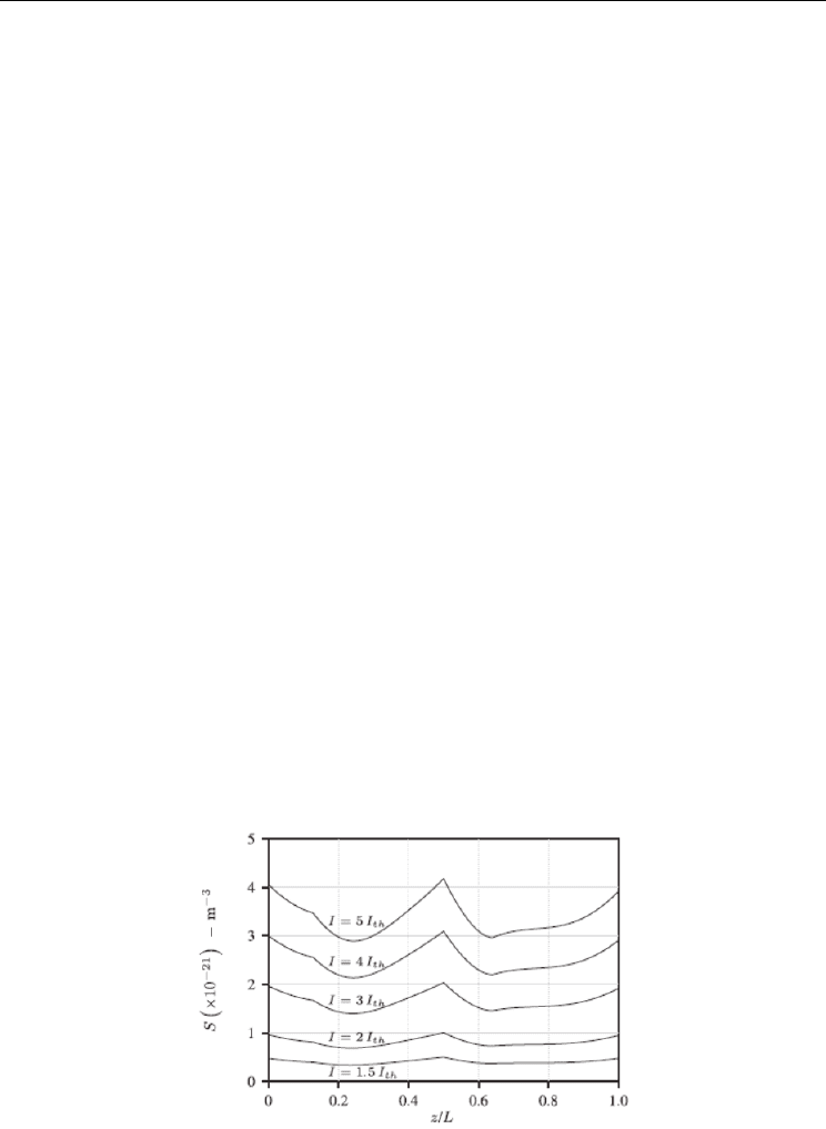
Fig.8 shows the photon distribution in the asymmetric structure for different bias currents. It
shows the gradual increase of the photon number in the whole structure, due to the
stimulated emission. The 3PS-DFB lasers include local maxima other than the central one,
leading to flatter distributions than those obtained for the QWS structure. Moreover, both
3PS-DFB lasers show smaller differences between the central photon density and the
escaping photon densities at the facets, thus benefitting the laser performance as far as the
emitted power is concerned, as it shall be seen later in the light-current stationary
characteristics of these structures (Fig. 12).
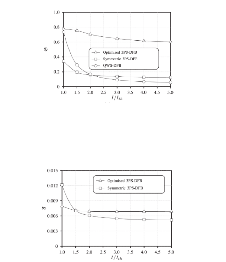
Fig.9 shows the laser mode selectivity vs. current injection. Similar mode discriminations at
threshold for the asymmetric 3PS and the QWS at threshold can be seen. Nevertheless, the
mode selectivity has a severe reduction with increasing bias current for the QWS case,
showing that the laser is strongly affected by the SHB effect. For the symmetric 3PS-DFB laser,
it is apparent that the stability related to flatter photon profiles was obtained at an expense of a
great reduction in the mode selectivity, while the situation is reverted at high values of biasing
currents. Undoubtedly, the best option is the asymmetric 3PS optimized structure.
Fig. 8.
()
Sz in the optimized asymmetric 3PS-DFB laser structure under different biasing
currents.
Numerical Simulations of Physical and Engineering Processes
462
Fig. 9. Mode selectivity vs. current injection for the 3 structures under analysis.
Fig.10 focuses on the evolution of the flatness with current injection for the two 3PS-DFB
lasers, showing a monotonically decreasing function for both structures. It should be
emphasized that the flatness lies in the range defined by the selection criteria for both lasers,
which is not definitely the case for the QWS-DFB, since this structure presents high-non
uniformities in the photon profile ( 0.3ℑ= at threshold, and 0.079ℑ= for 5 ).
th
II=×
Notice
that the QWS-DFB laser flatness falls outside the axis limits.
Fig. 10. Flatness vs. current injection for the three laser structures under analysis.
A comparative analysis of the three laser structures may be observed in Fig.11 to Fig.14, as
far as the emitted power and wavelength are concerned. In the current range 1 / 5,
th
II≤≤
relative variations in the emitted wavelengths
()
/
th
Δλ λ
of
43
9.4 10 %, 1.5 10 %
−−
××
and
3
5.5 10 %
−
× are observed for the asymmetric, the symmetric and the QWS lasers, respectively
(Fig.11). Under similar normalized current injections the asymmetric structure shows larger
values for the optical output power, measured at the right facet (Fig.12). This may be
explained by the increase of the escaping photon density at right facet related to the induced
