ASME Section VIII div 2 2010. ASME Boiler and Pressure Vessel Code. Alternative Rules
Подождите немного. Документ загружается.

2010 SECTION VIII, DIVISION 2
4-215
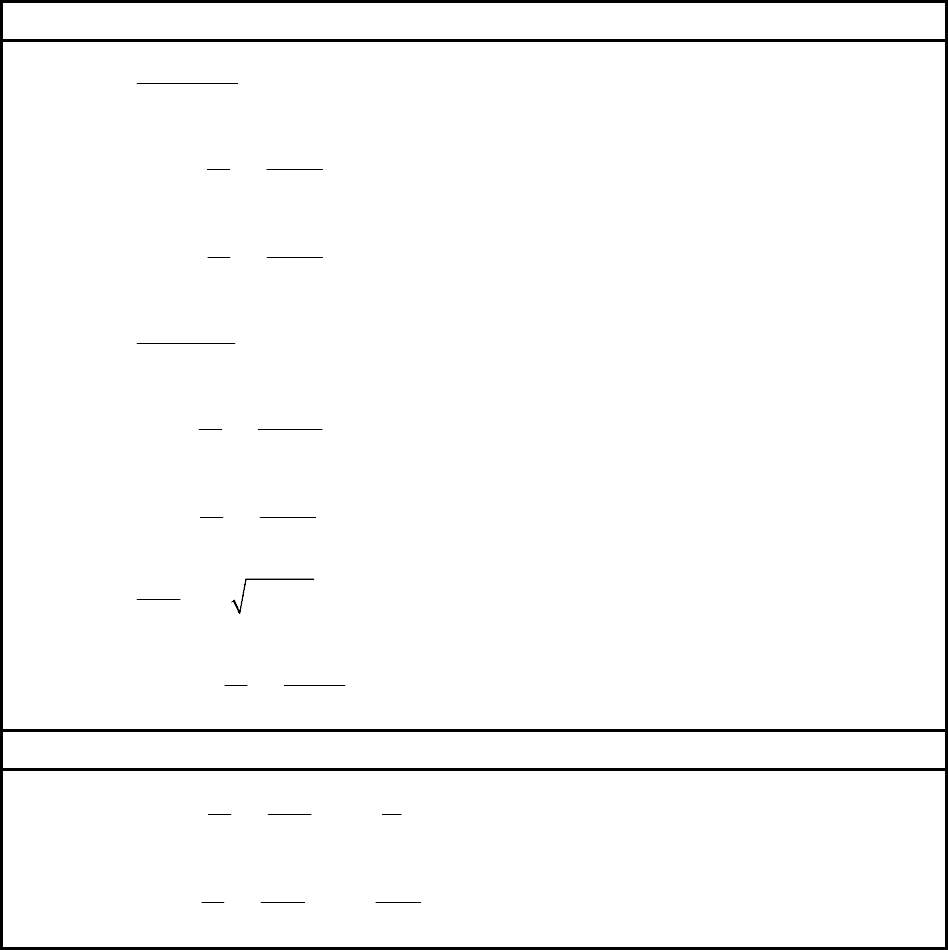
Table 4.12.4 – Stress Calculations And Acceptance Criteria For Type 3 Noncircular Vessels
(Chamfered Rectangular Cross Section)
Membrane And Bending Stresses – Critical Locations of Maximum Stress
()
2
1
s
m
m
PR L
S
tE
+
=
()
2
212
1
222
2
sC sC
ii
bi bo A
ob
cbc
S S M P RL RL L
cIE
⎛⎞
⎡⎤
=− = + − +
⎜⎟
⎣⎦
⎝⎠
()
22
2211
1
222
2
sD sD
ii
bi bo A
ob
cbc
SS MPLRLRLL
cIE
⎛⎞
⎡⎤
=− = + + − −
⎜⎟
⎣⎦
⎝⎠
()
1
1
l
m
m
PR L
S
tE
+
=
1
lA lA
iAi
bi bo
ob
cbMc
SS
cIE
⎛⎞
=− =
⎜⎟
⎝⎠
2
2
1
2
2
lB lB
ii
bi bo A
ob
cbc
SS MPL
cIE
⎛⎞
⎡⎤
=− = +
⎜⎟
⎣⎦
⎝⎠
(
)
22
21
1
c
m
m
P
SRLL
tE
=++
1
cBC cBC
iri
bi bo
ob
cbMc
SS
cIE
⎛⎞
=− =
⎜⎟
⎝⎠
Membrane And Bending Stresses – Defined Locations for Stress Calculation
()
222
2211
1
22
2
sX sX
ii
bi bi A
ob
cbc
P
S S M L RL RL L X
cIE
⎛⎞
⎡⎤
=− = + + − − +
⎜⎟
⎢⎥
⎣⎦
⎝⎠
2
1
2
lY lY
ii
bi bi A
ob
cbc
PY
SS M
cIE
⎛⎞
⎡⎤
=− = +
⎜⎟
⎢⎥
⎣⎦
⎝⎠
2010 SECTION VIII, DIVISION 2
4-216
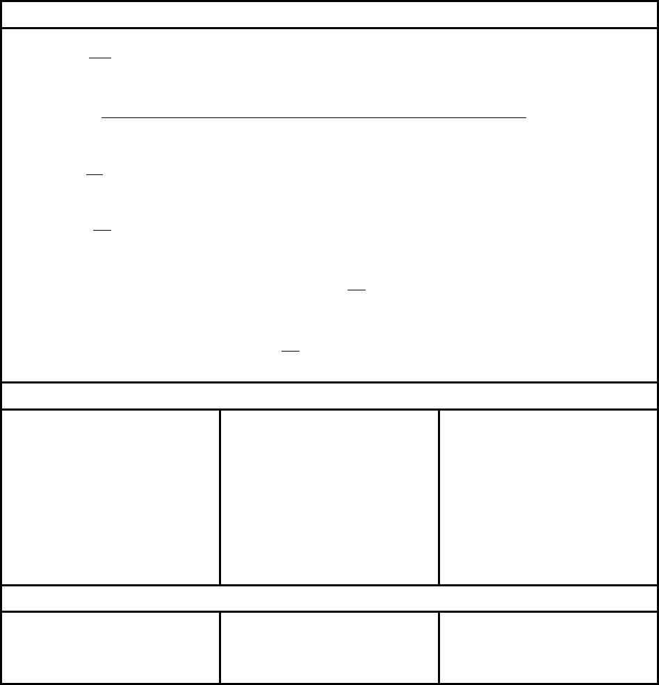
Table 4.12.4 – Stress Calculations And Acceptance Criteria For Type 3 Noncircular Vessels
(Chamfered Rectangular Cross Section)
Equation Constants
3
1
1
12
bt
I =
()
()
22 2 23 2 2
13 33 33
3
636 3621.5 6
32 2
A
PL
M
φ
απφ φαα φ πφα φα
απφ
−−+++−−++
=
++
1
R
L
φ
=
2
3
1
α
=
L
L
()
{}
2
2
21
cos 1 sin
2
rA
L
MMPRL L
θθ
⎛⎞
=+ − − +
⎜⎟
⎝⎠
1
2
arctan
r
L
M is a maximum at
L
θ
⎛⎞
=
⎜⎟
⎝⎠
Acceptance Criteria – Critical Locations of Maximum Stress
s
m
SS≤
1.5
ssC
mbi
SS S+≤
1.5
ssC
mbo
SS S+≤
1.5
ssD
mbi
SS S+≤
1.5
ssD
mbo
SS S+≤
l
m
SS
≤
1.5
llA
mbi
SS S+≤
1.5
llA
mbo
SS S+≤
1.5
llB
mbi
SS S+≤
1.5
llB
mbo
SS S+≤
c
m
SS≤
1.5
ccBC
mbi
SS S+≤
1.5
ccBC
mbo
SS S+≤
Acceptance Criteria – Defined Locations for Stress Calculation
1.5
ssX
mbi
SS S+≤
1.5
ssX
mbo
SS S+≤
1.5
llX
mbi
SS S+≤
1.5
llX
mbo
SS S+≤
Not Applicable
标准分享网 www.bzfxw.com 免费下载
2010 SECTION VIII, DIVISION 2
4-217
Table 4.12.4 – Stress Calculations And Acceptance Criteria For Type 3 Noncircular Vessels
(Chamfered Rectangular Cross Section)
Nomenclature For Stress Results
s
m
S
membrane stress in the short side.
,
s
CsC
bi bo
SS bending stress in the short side at point C on the inside and outside surfaces,
respectively.
,
s
DsD
bi bo
SS bending stress in the short side at point D on the inside and outside surfaces,
respectively.
,
s
XsX
bi bo
SS
bending stress in the short side at a point defined by
X
on the inside and outside
surfaces, respectively.
l
m
S membrane stress in the long side.
,
lA lA
bi bo
SS bending stress in the long side at point A on the inside and outside surfaces,
respectively.
,
lB lB
bi bo
SS
bending stress in the long side at point B on the inside and outside surfaces,
respectively.
,
lY lY
bi bo
SS bending stress in the long side at a point defined by Y on the inside and outside
surfaces, respectively.
c
m
S membrane stress in the circular arc between B and C.
,
cBC cBC
bi bo
SS
bending stress in the circular arc between B and C on the inside and outside surfaces,
respectively.
2010 SECTION VIII, DIVISION 2
4-218
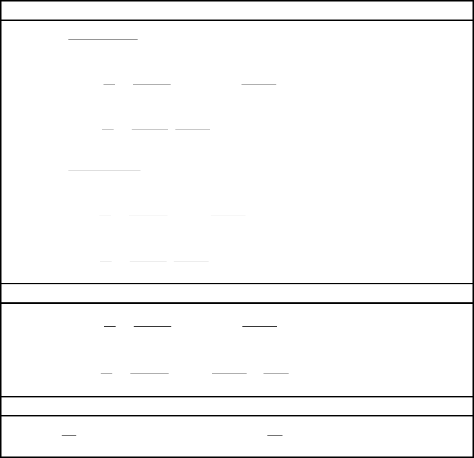
Table 4.12.5 – Stress Calculations And Acceptance Criteria For Type 4 Noncircular Vessels
(Reinforced Rectangular Cross Section)
Membrane And Bending Stresses – Critical Locations of Maximum Stress
()
11
2
s
m
m
Php
S
AtpE
=
+
2
22
1
11
1
32
24 1
sC sC
ii
bi bo
ob
cPpc
k
SS Hh
cIE k
α
⎡⎤
⎛⎞
⎛⎞
+
=− = − +
⎢⎥
⎜⎟
⎜⎟
+
⎝⎠
⎝⎠
⎣⎦
2
2
1
11
1
12 1
sB sB
ii
bi bo
ob
cPhpc
k
SS
cIEk
α
⎛⎞
⎡⎤
+
=− =
⎜⎟
⎢⎥
+
⎣⎦
⎝⎠
()
22
2
l
m
m
PHp
S
AtpE
=
+
2
2
1
21
1
32
24 1
lA lA
ii
bi bo
ob
cPhpc
k
SS
cIE k
α
⎡⎤
⎛⎞
⎛⎞
+
=− = − +
⎢⎥
⎜⎟
⎜⎟
+
⎝⎠
⎝⎠
⎣⎦
2
2
1
21
1
12 1
lB lB
ii
bi bo
ob
cPhpc
k
SS
cIEk
α
⎛⎞
⎡⎤
+
=− =
⎜⎟
⎢⎥
+
⎣⎦
⎝⎠
Membrane And Bending Stresses – Defined Locations for Stress Calculation
2
22 2
1
11
1
32 12
24 1
sX sX
ii
bi bo
ob
cPpc
k
SS Hh X
cIE k
α
⎡⎤
⎛⎞
⎛⎞
+
=− = − + +
⎢⎥
⎜⎟
⎜⎟
+
⎝⎠
⎝⎠
⎣⎦
2
22
1
2
21
1
12
32
24 1
lY lY
ii
bi bo
ob
cPhpc
k
Y
SS
cIE kh
α
⎡⎤
⎛⎞
⎛⎞
+
=− = − + +
⎢⎥
⎜⎟
⎜⎟
+
⎝⎠
⎝⎠
⎣⎦
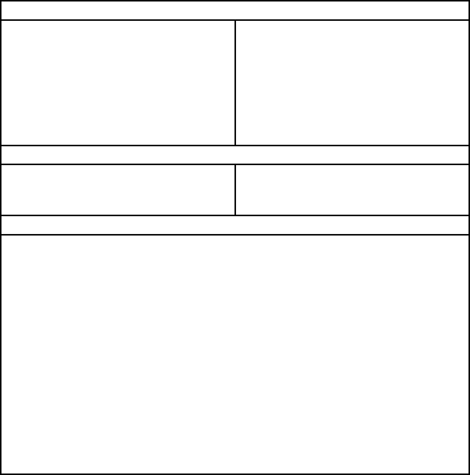
Equation Constants
21
1
11
I
k
I
α
=
1
1
1
H
h
α
=
标准分享网 www.bzfxw.com 免费下载
2010 SECTION VIII, DIVISION 2
4-219
Table 4.12.5 – Stress Calculations And Acceptance Criteria For Type 4 Noncircular Vessels
(Reinforced Rectangular Cross Section)
Acceptance Criteria – Critical Locations of Maximum Stress
s
m
SS≤
1.5
ssC
mbi
SS S+≤
1.5
ssC
mbo
SS S+≤
1.5
ssB
mbi
SS S+≤
1.5
ssB
mbo
SS S+≤
l
m
SS
≤
1.5
llA
mbi
SS S+≤
1.5
llA
mbo
SS S+≤
1.5
llB
mbi
SS S+≤
1.5
llB
mbo
SS S+≤
Acceptance Criteria – Defined Locations for Stress Calculation
1.5
ssX
mbi
SS S+≤
1.5
ssX
mbo
SS S+≤
1.5
llY
mbi
SS S+≤
1.5
llY
mbo
SS S+≤
Nomenclature For Stress Results
s
m
S membrane stress in the short side.
,
s
BsB
bi bo
SS bending stress in the short side at point B on the inside and outside surfaces,
respectively.
,
s
CsC
bi bo
SS
bending stress in the short side at point C on the inside and outside surfaces,
respectively.
,
s
XsX
bi bo
SS bending stress in the short side at a point defined by
X
on the inside and outside
surfaces, respectively.
l
m
S membrane stress in the long side.
,
lB lB
bi bo
SS
bending stress in the long side at point B on the inside and outside surfaces,
respectively.
,
lA lA
bi bo
SS bending stress in the long side at point A on the inside and outside surfaces,
respectively.
,
lY lY
bi bo
SS bending stress in the long side at a point defined by
Y
on the inside and outside
surfaces, respectively.
s
t
m
S membrane stress in the stay bar or plate, as applicable.
2010 SECTION VIII, DIVISION 2
4-220
Table 4.12.6 – Stress Calculations And Acceptance Criteria For Type 5 Noncircular Vessels
(Reinforced Rectangular Cross Section With Chamfered Corners)
Membrane And Bending Stresses – Critical Locations of Maximum Stress
()
221
1
s
m
m
PR L L
S
tE
++
=
()
()
2
221
221111
1
2
2
sE sE
ii
bi bo A
ob
LL
cc
SS MPp RLLLL
cIE
⎡⎤
⎧
⎫
+
⎛⎞
⎪
⎪
⎢⎥
=− = + + + − −
⎨
⎬
⎜⎟
⎢⎥
⎝⎠
⎪
⎪
⎩⎭
⎣⎦
()
222
2 2 21 21 1 11 11
1
221111
22
2
2
sF sF
ii
bi bo A
ob
LLLL LLL
cc
Pp
SS M
cIE
RL L L L
⎡⎤
⎧
⎫
+
+− −+
⎛⎞
⎪
⎪
=− = +
⎢⎥
⎨
⎬
⎜⎟
+−−
⎢⎥
⎪
⎪
⎝⎠
⎩⎭
⎣⎦
()( )()
{}
22
2 21 2 21111 111
11
2
2
sG sG
ii
bi bo A
ob
cc
Pp
SS M LL RLLLLLL
cIE
⎛⎞
⎡⎤
=− = + + + + − − − +
⎜⎟
⎢⎥
⎣⎦
⎝⎠
()
111
2
l
m
m
PR L L
S
tE
++
=
21
lA lA
iAi
bi bo
ob
cMc
SS
cIE
⎛⎞
=− =
⎜⎟
⎝⎠
2
2
2
2
lB lB
ii
bi bo A
ob
cc
PpL
SS M
cIE
⎛⎞
⎡⎤
=− = +
⎜⎟
⎢⎥
⎣⎦
⎝⎠
()
2
221
2
2
lC lC
ii
bi bo A
ob
Pp L L
cc
SS M
cIE
⎡⎤
+
⎛⎞
=− = +
⎢⎥
⎜⎟
⎢⎥
⎝⎠
⎣⎦
()()
22
221 211
1
c
m
m
P
S R LL LL
tE
⎛⎞
= ++++
⎜⎟
⎝⎠
1
cD cD
iri
bi bo
ob
cMc
SS
cIE
⎛⎞
=− =
⎜⎟
⎝⎠
标准分享网 www.bzfxw.com 免费下载
2010 SECTION VIII, DIVISION 2
4-221
Table 4.12.6 – Stress Calculations And Acceptance Criteria For Type 5 Noncircular Vessels
(Reinforced Rectangular Cross Section With Chamfered Corners)
Membrane And Bending Stresses – Defined Locations for Stress Calculation
()( )
()
2
221 221111
1
2
2
11
111
2
2
⎡⎤
⎧⎫
++ +−−−
⎛⎞
⎪⎪
⎢⎥
=− = + ≤
⎨⎬
⎜⎟
⎢⎥
⎝⎠
++
⎪⎪
⎩⎭
⎣⎦
sX sX
ii
bi bo A
ob
LL RLL LL
cc
Pp
SS M XL
cIE
LL X
()
222
2 2 21 21 1 11 11
1
2
1
221111
22
2
2
⎡⎤
⎧⎫
++−−+
⎛⎞
⎪⎪
=− = + >
⎢⎥
⎨⎬
⎜⎟
+−− +
⎢⎥
⎝⎠
⎪⎪
⎩⎭
⎣⎦
sX sX
ii
bi bo A
ob
LLLL LLL
cc
Pp
SS M XL
cIE
RL L L L X
2
2
21
2
lY lY
ii
bi bo A
ob
cc
PpY
SS M YL
cIE
⎡⎤
⎛⎞
=− = + ≤
⎢⎥
⎜⎟
⎝⎠
⎣⎦
2
2
2
2
⎡⎤
⎛⎞
=− = + >
⎢⎥
⎜⎟
⎝⎠
⎣⎦
lY lY
ii
bi bo A
ob
cc
PpY
SS M YL
cIE
Equation Constants
3
1
1
12
p
t
I =
3
2
2
12
p
t
I =
()
(
)
()()()
()()()
222
2 2 21 21 21 11
2 21 2 21 11 2 11 2 21 11 21
233
1
1 11 11 1 11 11 2
21
22 2 23
2 211 21 211 111 111 1
1
11
3 4 12 3 2 12
626262
62 6 2 42
633632
2
6
A
RL R L L R RL L RL
LL L L R L LL R L L L R L
I
LL R L R L L L L
I
LLLLLLLLL LL L
I
I
R
MPp
ππ
π
π
−+− +++−
+++ − +− + +
⎛⎞
++ − ++− −
⎜⎟
⎝⎠
++ − − −−
⎛⎞
⎜⎟
⎝⎠
=
{}
2
1 21 211 111
11
21 11 1 2
11 21
62 2 2 2
LLLLLLL
II
LLRL L
II
π
⎡⎤
⎢⎥
⎢⎥
⎢⎥
⎢⎥
⎢⎥
⎢⎥
⎢⎥
⎛⎞
⎢⎥
⎜⎟
⎢⎥
⎜⎟
−− +
⎝⎠
⎣⎦
⎡⎤
⎧⎫
⎛⎞ ⎛⎞
⎪⎪
+++ +
⎢⎥
⎨⎬
⎜⎟ ⎜⎟
⎪⎪
⎢⎥⎝⎠ ⎝⎠
⎩⎭
⎣⎦
() ()( )
2
221
221 111
cos 1 sin
2
rA
LL
MMPpLL R RRLLR
θθ
⎧⎫
+
⎛⎞
⎡
⎤
=+ + + +− − ++
⎨⎬
⎜⎟
⎣
⎦
⎝⎠
⎩⎭
111
221
arctan
cD
bi r D
LL
S is a maximum when M M when
LL
θ
⎛⎞
+
==
⎜⎟
+
⎝⎠
2010 SECTION VIII, DIVISION 2
4-222
Table 4.12.6 – Stress Calculations And Acceptance Criteria For Type 5 Noncircular Vessels
(Reinforced Rectangular Cross Section With Chamfered Corners)
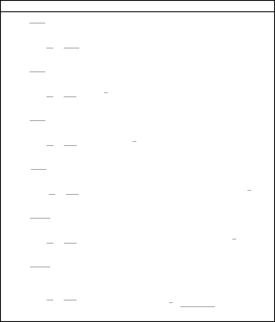
Acceptance Criteria – Critical Locations of Maximum Stress
s
m
SS≤
1.5
ssE
mbi
SS S+≤
1.5
ssE
mbo
SS S+≤
1.5
ssF
mbi
SS S+≤
1.5
ssF
mbo
SS S+≤
1.5
ssG
mbi
SS S+≤
1.5
ssG
mbo
SS S+≤
l
m
SS
≤
1.5
llA
mbi
SS S+≤
1.5
llA
mbo
SS S+≤
1.5
llB
mbi
SS S+≤
1.5
llB
mbo
SS S+≤
1.5
llC
mbi
SS S+≤
1.5
llC
mbo
SS S+≤
c
m
SS≤
1.5
ccD
mbi
SS S+≤
1.5
ccD
mbo
SS S+≤
Acceptance Criteria – Defined Locations for Stress Calculation
1.5
ssX
mbi
SS S+≤
1.5
ssX
mbo
SS S+≤
1.5
llY
mbi
SS S+≤
1.5
llY
mbo
SS S+≤
Not Applicable
Nomenclature For Stress Results
s
m
S membrane stress in the short side.
,
s
EsE
bi bo
SS
bending stress in the short side at point E on the inside and outside surfaces,
respectively.
,
s
FsF
bi bo
SS bending stress in the short side at point F on the inside and outside surfaces,
respectively.
,
s
GsG
bi bo
SS bending stress in the short side at point G on the inside and outside surfaces,
respectively.
,
s
XsX
bi bo
SS bending stress in the short side at a point defined by
X
on the inside and outside
surfaces, respectively.
l
m
S membrane stress in the long side.
,
lA lA
bi bo
SS bending stress in the long side at point A on the inside and outside surfaces, respectively.
,
lB lB
bi bo
SS
bending stress in the long side at point B on the inside and outside surfaces, respectively.
,
lC lC
bi bo
SS bending stress in the long side at point C on the inside and outside surfaces,
respectively.
,
lY lY
bi bo
SS bending stress in the long side at a point defined by Y on the inside and outside
surfaces, respectively.
c
m
S
membrane stress in the circular arc between B and E.
,
cD cD
bi bo
SS bending stress in the circular arc at point B on the inside and outside surfaces,
respectively.
标准分享网 www.bzfxw.com 免费下载
2010 SECTION VIII, DIVISION 2
4-223
Table 4.12.7 – Stress Calculations And Acceptance Criteria For Type 6 Noncircular Vessels
(Reinforced Octagonal Cross Section With Chamfered Corners)
Membrane And Bending Stresses – Critical Locations of Maximum Stress
3
A
m
cm
PpL
S
AE
=
21
AA
iAi
bi bo
ob
cMc
SS
cIE
⎛⎞
=− =
⎜⎟
⎝⎠
3
B
m
cm
PpL
S
AE
=
2
22
1
BB
ii
bi bo A A
ob
cc
SS MVYWL
cIE
⎛⎞
⎡⎤
=− = − +
⎜⎟
⎣⎦
⎝⎠
3
C
m
cm
PpL
S
AE
=
2
532
1
2
CC
ii
bi bo A
ob
cc
SS MWKLWY
cIE
⎛⎞
⎡⎤
=− = + −
⎜⎟
⎣⎦
⎝⎠
()
()
()
0.5
2
2
3
cos
M
mMMMM
cm
Pp
SCLE
AE
θ
β
=+− −
{}
()
22
31 2
1
22
MM
ii
bi bo A M M M M M M M M
ob
cc
SS MWCCVEEWLEtWY
cIE
⎛⎞
⎡⎤
=− = + + + − − + − +
⎜⎟
⎣⎦
⎝⎠
D
D
E
m
cm
PpO
S
AE
=
{}
()
22
331 1 113 111 2
1
22
DD
ii
bi bi A
ob
cc
SS MWCCVEEWLEtWY
cIE
θθ θ
⎛⎞
⎡⎤
=− = + + + − − + − +
⎜⎟
⎣⎦
⎝⎠
U
D
E
m
cm
PpO
S
AE
=
{}{}{ }
{}
()
22
32 321 12
11
1
12 1 32 12
1cos
2
2
YY X
UU
ii
bi bi A
ob
XX
CU CU V E U
cc
SS MW
t
cIE
EUW LY EU
θ
θθ
θ
⎡⎤
⎛⎞
+++ ++ −
⎢⎥
⎜⎟
⎛⎞
=− = +
⎢⎥
⎜⎟
⎜⎟
⎧
⎫
−
+−+ ++
⎢⎥
⎜⎟⎝⎠
⎨
⎬
⎜⎟
⎢⎥
⎩⎭
⎝⎠
⎣⎦
2010 SECTION VIII, DIVISION 2
4-224
Table 4.12.7 – Stress Calculations And Acceptance Criteria For Type 6 Noncircular Vessels
(Reinforced Octagonal Cross Section With Chamfered Corners)
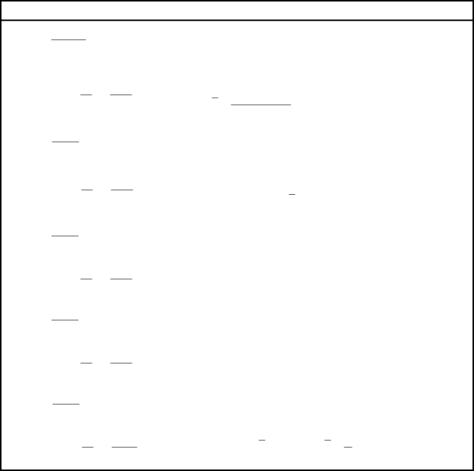
Membrane And Bending Stresses – Critical Locations of Maximum Stress
E
D
E
m
cm
PpO
S
AE
=
()
22
111 2 21
11
1
32 2
1cos
2
2
EE E E
EE
ii
bi bo A
ob
E
CCVC CW
cc
SS MW
t
cIE
LY C
θ
⎡⎤
⎛⎞
++− −
⎢⎥
⎜⎟
⎛⎞
=− = +
⎧
⎫
−
⎢⎥
⎜⎟
⎜⎟
++
⎨
⎬
⎝⎠
⎢⎥
⎜⎟
⎩⎭
⎝⎠
⎣⎦
()
()
0.5
22
cos
N
mMKNN
cm
Pp
SCO
AE
θ
β
=+ −
{}{}{ }
{}
{}
22
44 1
1
13211
222
NNNN
NN
ii
bi bo A
ob
NN N N
LF LFV MG
cc
SS MW
cIE
MGW LYt M G W
⎡⎤
⎛⎞
−+− ++−
⎛⎞
⎢⎥
⎜⎟
=− = +
⎜⎟
⎜⎟
⎢⎥
−−++−−
⎝⎠
⎝⎠
⎣⎦
4
F
m
cm
PpL
S
AE
=
()
22
441 1 32
1
2
FF
ii
bi bo A
ob
cc
SS MWLLtMLJ
cIE
⎛⎞
⎡⎤
=− = + + + −
⎜⎟
⎣⎦
⎝⎠
4
G
m
cm
PpL
S
AE
=
{}{}
()
2
2
441 111 3211
1
2
GG
ii
bi bo A
ob
cc
SS MWLLtML LJL
cIE
⎛⎞
⎡⎤
=− = + + + + − +
⎜⎟
⎢⎥
⎣⎦
⎝⎠
4
H
m
cm
PpL
S
AE
=
22
1
441 413 32
11
22
2
HH
ii
bi bo A
ob
cc
t
SS MWLLtLYLLY
cIE
⎡⎤
⎛⎞
⎛⎞
⎧
⎫
=− = + + + − − +
⎨
⎬
⎜⎟
⎢⎥
⎜⎟
⎩⎭
⎝⎠
⎝⎠
⎣⎦
标准分享网 www.bzfxw.com 免费下载
