ASME Section VIII div 2 2010. ASME Boiler and Pressure Vessel Code. Alternative Rules
Подождите немного. Документ загружается.

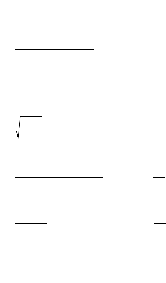
2010 SECTION VIII, DIVISION 2
4-205
*
1.0
1
ab
a
a
e
SS
F
S
S
F
+≤
⎛⎞
−
⎜⎟
⎝⎠
(4.12.51)
where
()( )
()()
12
1221
22
2222
++
=
++ +
e
a
Ph t H t
S
tH t th t
(4.12.52)
()( )
12
22
ee
b
e
Ph t H t yc
S
I
⎡⎤
++
⎣⎦
=
(4.12.53)
2
2
y
c
y
E
C
S
π
= (4.12.54)
2
2
3
3
2
1
1
2
2
22
53 1
38 8
v
y
cge
v
a c
ge
vv
cge c ge
L
S
CR
L
FwhenC
R
LL
CR CR
⎡⎤
⎛⎞
⎢⎥
−
⎜⎟
⎜⎟
⎢⎥
⎝⎠
⎣⎦
=≤
⎛⎞ ⎛⎞
+−
⎜⎟ ⎜⎟
⎜⎟ ⎜⎟
⎝⎠ ⎝⎠
(4.12.55)
2
2
12
2
2
23
y
v
a c
ge
v
ge
E
L
FwhenC
R
L
R
π
=>
⎛⎞
⎜⎟
⎜⎟
⎝⎠
(4.12.56)
2
*
2
12
2
23
y
e
v
ge
E
F
L
R
π
=
⎛⎞
⎜⎟
⎜⎟
⎝⎠
(4.12.57)
4.12.9 Rectangular Vessels With Two or More Compartments of Unequal Size
Typical rectangular cross section vessels having unequal compartments are shown in Figure 4.12.15. These
types of vessels shall be qualified using either of the two methods shown below.
a) A design can be qualified by selecting the compartment having the maximum dimensions and analyzing
the vessel as a Type 7 for the case of a two-compartment vessel or Type 8 for the case of a vessel with
more than two compartments. For example, if the vessel has two unequal compartments, use the
geometry for a Type 7 with each compartment having the maximum dimension of the actual vessel. For
a vessel with more than two compartments, use the geometry for a Type 8 with three compartments
having the maximum dimensions of the actual vessel. Thus a five or six compartment vessel would be
analyzed as if it had only three compartments.
b) The vessel can be designed in accordance with Part 5 .

2010 SECTION VIII, DIVISION 2
4-206
4.12.10 Fabrication
4.12.10.1 Provided the requirements of the applicable Parts of this Division are satisfied, fabrication
methods other than welding are permitted.
4.12.10.2 Category A joints may be of Type 3 when the thickness does not exceed 16 mm (0.625 in.).
4.12.11 Nomenclature
4.12.11.1 The nomenclature used in this paragraph is defined below except for computed stresses. The
nomenclature for computed stress is defined in paragraph 4.12.11.2.
1
A cross-sectional area of the reinforcing member associated with
1
t .
2
A cross-sectional area of the reinforcing member associated with
2
t .
b unit width per cross section. In the equations for the areas, moments of inertia, and bending
moments for all vessel configurations without external reinforcements are given for cross
sections with a unit width.
C
stress factor for braced and stayed surfaces (see Table 4.9.1).
e
c location from the neutral axis to the outer most surface of a composite section associated
,,
vR
tRA.
i
c distance from the neutral axis to the inside surface of the shell or reinforcing member on the
short side, long side, curved element, or stay plate as applicable (e.g. for a plate with uniform
holes without a stiffener,
2ct
=
where t is the thickness of the plate); the sign of this
parameter is always positive (the sign for the bending stress is included in the applicable
equation).
o
c distance from the neutral axis to the outside surface of the shell or reinforcing member on the
short side, long side, curved element, or stay plate as applicable (e.g. for a plate with uniform
holes without a stiffener,
2ct
=
where t is the thickness of the plate); the sign of this
parameter is always positive (the sign for the bending stress is included in the applicable
equation).
Δ effective width coefficient (see Table 4.12.14)
j
d
hole diameter
jth
location.
b
e bending stress ligament efficiency of a hole pattern.
m
e membrane stress ligament efficiency of a hole pattern.
E weld joint factor.
b
E factor applied to the bending stress to account for a ligament or weld joint factor.
m
E factor applied to the membrane stress to account for a ligament or weld joint factor.
y
E Young’s Modulus from Annex 3.E at design temperature.
ya
E
Young’s Modulus from Annex 3.E at ambient temperature.
H inside length of the short side of a rectangular vessel. For Types 5 and 6,
111
2( )HLL=+
and for Type 10
2HR= .
1
H centroidal length of the reinforcing member on the short side of a rectangular vessel.
h inside length of the long side of a rectangular vessel. For Types 5 and 6,
221
2( )hLL=+
and for Type 10
2
2HL= .
标准分享网 www.bzfxw.com 免费下载
2010 SECTION VIII, DIVISION 2
4-207
1
h centroidal length of the reinforcing member on the long side of a rectangular vessel.
e
I
least moment of inertia of noncircular cross-section vessel.
1
I
moment of inertia of strip thickness
1
t .
2
I
moment of inertia of strip thickness
2
t .
22
I
moment of inertia of strip thickness
22
t .
3
I
moment of inertia of strip thickness
3
t .
11
I
moment of inertia of combined reinforcing member and effective with of plate w of thickness
1
t .
21
I
moment of inertia of combined reinforcing member and effective with of plate w of thickness
2
t .
1
L half-length of the short side of a rounded vessel without reinforcement or the half-length of
reinforcement on the short side for a reinforced rectangular vessel.
2
L half-length of the long side of a rounded vessel without reinforcement or the half-length of
reinforcement on the long side for a reinforced rectangular vessel.
3
L half-length dimension of the short side of Type 5 and Type 6 rectangular vessel.
4
L half-length dimension of the long side of Type 5 and Type 6 rectangular vessel.
11
L length measured from the edge of the reinforcement to the end of the straight side of the
short side of a Type 5 and Type 6 rectangular vessel.
21
L length measured from the edge of the reinforcement to the end of the straight side of the long
side of a Type 5 and Type 6 rectangular vessel.
v
L length of the vessel.
A
M
bending moment at the mid-side of the long side, a positive sign indicates a compressive
stress on the outside surface of the plate.
N rectangular vessel parameter.
P internal design pressure.
1
P internal design pressure of a two compartment vessel where
12
PP≥ .
2
P internal design pressure of a two compartment vessel where
12
PP≥ .
p
distance between reinforcing members; plate width between edges of reinforcing members
h
p
pitch distance between holes.
R
inside radius.
g
e
R
least radius of gyration of a noncircular cross-section vessel.
r radius to centroidal axis of reinforcement member on obround vessel.
S allowable stress from Annex 3.A at the design temperature.
y
S yield stress at the design temperature evaluated in accordance Annex 3.D .
t plate thickness.
1
t thickness of the short side plate.
2
t thickness of the long side plate.
3
t thickness or diameter of staying member.
4
t thickness or diameter of staying member.

2010 SECTION VIII, DIVISION 2
4-208
5
t thickness of end closure plate or head of vessel.
22
t thickness of the thicker long side plate.
j
T hole depth jth location.
ν
Poisson’s ratio.
w
width of plate included in the moment of inertia calculation of the reinforced section.
y
distance from geometric center of end plate to centroid of cross-sectional area of a
rectangular vessel.
4.12.11.2 The nomenclature for all computed stress quantities is shown in the following tables and figures.
a) For Types 1, 4, 7, and 8 noncircular vessels see Tables 4.12.2, 4.12.5, 4.12.8, and 4.12.9 and Figures
4.12.1, 4.12.4, 4.12.8, and 4.12.9
b) For the Type 2 noncircular vessel, see Table 4.12.3 and Figure 4.12.2
c) For the Type 3 noncircular vessel, see Table 4.12.4 and Figure 4.12.3
d) For the Type 5 noncircular vessel, see Table 4.12.6 and Figure 4.12.5
e) For the Type 6 noncircular vessel, see Table 4.12.7 and Figures 4.12.6 and 4.12.)
f) For the Types 9, 10, and 11 noncircular vessels, see Tables 4.12.10, 4.12.11. and 4.12.12 and Figures
4.12.10, 4.12.11, and 4.12.12
g) For the Type 12 noncircular vessels, see Table 4.12.13 and Figure 4.12.13
h) For the compressive stress calculations for Type 1 and 2 see Table 4.12.15
标准分享网 www.bzfxw.com 免费下载
2010 SECTION VIII, DIVISION 2
4-209
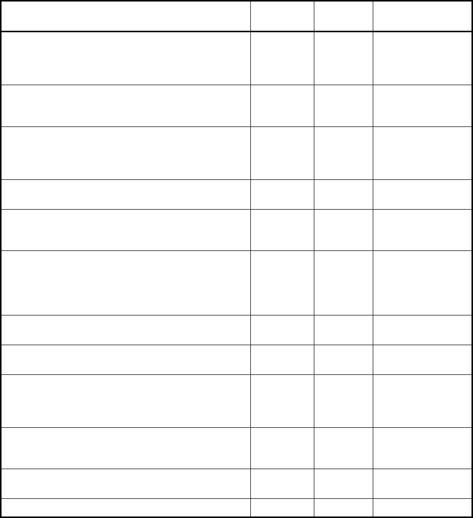
4.12.12 Tables
Table 4.12.1 – Noncircular Vessel Configurations And Types
Configuration Type
Figure
Number
Table Containing
Design Rules
Rectangular cross-section in which the opposite
sides have the same wall thickness. Two opposite
sides may have a wall thickness different than that of
the other two opposite sides.
1 4.12.1 4.12.2
Rectangular cross-section in which two opposite
members have the same thickness and the other two
members have two different thicknesses.
2 4.12.2 4.12.3
Rectangular cross section having uniform wall
thickness and corners bent to a radius. For corners
which are cold formed, the provisions Part 6 shall
apply
3 4.12.3 4.12.4
Rectangular cross-section similar to Type 1 but
reinforced by stiffeners welded to the sides.
4 4.12.4 4.12.5
Rectangular cross-section similar to Type 3 but
externally reinforced by stiffeners welded to the flat
surfaces of the vessel.
5 4.12.5 4.12.6
Rectangular cross section with chamfered corner
segments (octagonal cross-section) joined to the
adjacent sides by small curved segments with
constant radii and reinforced by stiffeners welded to
the flat surfaces of the vessel.
6
4.12.6,
4.12.7
4.12.7
Rectangular cross section similar to Type 1 but
having two opposite sides stayed at mid-length.
7 4.12.8 4.12.8
Rectangular cross section similar to Type 1 but
having two opposite sides stayed at the third points.
8 4.12.9 4.12.9
Obround cross-section in which the opposite sides
have the same wall thickness. The flat sidewalls may
have a different thickness than the semi-cylindrical
parts.
9 4.12.10 4.12.10
Obround cross-section similar to Type 9 but
reinforced by stiffeners welded to the curved and flat
surfaces of the vessel.
10 4.12.11 4.12.11
Obround cross-section similar to Type 9 but having
the flat side plates stayed at mid-length.
11 4.12.12 4.12.12
Circular Section With A Single Stay Plate 12 4.12.13 4.12.13
2010 SECTION VIII, DIVISION 2
4-210
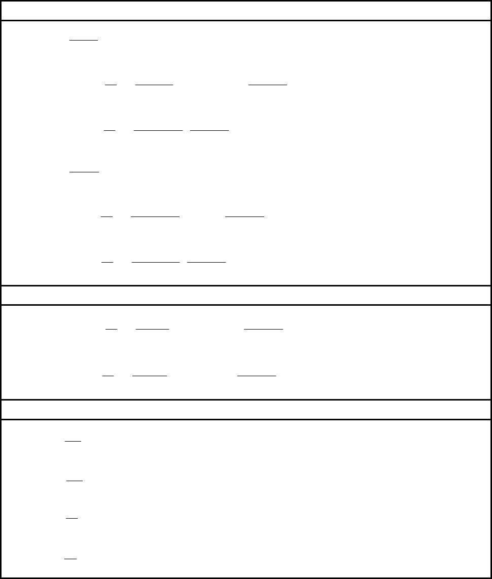
Table 4.12.2 – Stress Calculations And Acceptance Criteria For Type 1 Noncircular Vessels
(Rectangular Cross Section)
Membrane And Bending Stresses – Critical Locations of Maximum Stress
1
2
s
m
m
Ph
S
tE
=
2
22
2
1
1
1.5
12 1
sC sC
isi
bi bo
ob
cPbJc
K
SS Hh
cIE K
α
⎡⎤
⎛⎞
⎛⎞
+
=− = − +
⎢⎥
⎜⎟
⎜⎟
+
⎝⎠
⎝⎠
⎣⎦
2
2
3
1
1
12 1
sB sB
isi
bi bo
ob
cPbhJc
K
SS
cIEK
α
⎛⎞
⎡⎤
+
=− =
⎜⎟
⎢⎥
+
⎣⎦
⎝⎠
2
2
l
m
m
PH
S
tE
=
2
2
2
2
1
1.5
12 1
lA lA
ili
bi bo
ob
cPbhJc
K
SS
cIE K
α
⎡⎤
⎛⎞
⎛⎞
+
=− = − +
⎢⎥
⎜⎟
⎜⎟
+
⎝⎠
⎝⎠
⎣⎦
2
2
3
2
1
12 1
lB lB
ili
bi bo
ob
cPbhJc
K
SS
cIEK
α
⎛⎞
⎡⎤
+
=− =
⎜⎟
⎢⎥
+
⎣⎦
⎝⎠
Membrane And Bending Stresses – Defined Locations for Stress Calculation
2
22 2
1
1
1.5 6
12 1
sX sX
ii
bi bo
ob
cPbc
K
SS Hh X
cIE K
α
⎡⎤
⎛⎞
⎛⎞
+
=− = − + +
⎢⎥
⎜⎟
⎜⎟
+
⎝⎠
⎝⎠
⎣⎦
2
22 2
2
1
1.5 6
12 1
lY lY
ii
bi bo
ob
cPbc
K
SS hh Y
cIE K
α
⎡⎤
⎛⎞
⎛⎞
+
=− = − + +
⎢⎥
⎜⎟
⎜⎟
+
⎝⎠
⎝⎠
⎣⎦
Equation Constants
3
1
1
12
bt
I =
3
2
2
12
bt
I =
1
2
I
K
I
α
=
H
h
α
=
2
1.0 ( 4.12.5 )
s
J see paragraph for exception
=
3
1.0 ( 4.12.5 )
s
J see paragraph for exception
=
2
1.0 ( 4.12.5 )
l
J see paragraph for exception
=
3
1.0 ( 4.12.5 )
l
J see paragraph for exception
=
标准分享网 www.bzfxw.com 免费下载
2010 SECTION VIII, DIVISION 2
4-211
Table 4.12.2 – Stress Calculations And Acceptance Criteria For Type 1 Noncircular Vessels
(Rectangular Cross Section)
Acceptance Criteria – Critical Locations of Maximum Stress
s
m
SS≤
1.5
ssC
mbi
SS S+≤
1.5
ssC
mbo
SS S+≤
1.5
ssB
mbi
SS S+≤
1.5
ssB
mbo
SS S+≤
l
m
SS
≤
1.5
llA
mbi
SS S+≤
1.5
llA
mbo
SS S+≤
1.5
llB
mbi
SS S+≤
1.5
llB
mbo
SS S+≤
Acceptance Criteria – Defined Locations for Stress Calculation
1.5
ssX
mbi
SS S+≤
1.5
ssX
mbo
SS S+≤
1.5
llY
mbi
SS S+≤
1.5
llY
mbo
SS S+≤
Nomenclature For Stress Results
s
m
S membrane stress in the short side.
,
s
BsB
bi bo
SS bending stress in the short side at point B on the inside and outside surfaces, respectively.
,
s
CsC
bi bo
SS bending stress in the short side at point C on the inside and outside surfaces, respectively.
,
s
XsX
bi bo
SS
bending stress in the short side at a point defined by
X
on the inside and outside
surfaces, respectively.
l
m
S membrane stress in the long side.
,
lB lB
bi bo
SS bending stress in the long side at point B on the inside and outside surfaces, respectively.
,
lA lA
bi bo
SS bending stress in the long side at point A on the inside and outside surfaces, respectively.
,
lY lY
bi bo
SS
bending stress in the long side at a point defined by Y on the inside and outside surfaces,
respectively.
s
t
m
S membrane stress in the stay bar or plate, as applicable.
2010 SECTION VIII, DIVISION 2
4-212
Table 4.12.3 – Stress Calculations And Acceptance Criteria For Type 2 Noncircular Vessels
(Rectangular Cross Section With Unequal Side Plate Thicknesses)
Membrane And Bending Stresses – Critical Locations of Maximum Stress
1
2
s
m
m
Ph
S
tE
=
()()
2
2
3
212 222
1
4
sB sB
isi
bi bo
ob
cPbhJc
SS Kkk kKk
cNIE
α
⎛⎞
⎡⎤
=− = − + −
⎜⎟
⎣⎦
⎝⎠
()()
2
2
3
11 2 2 1 2
1
4
sC sC
isi
bi bo
ob
cPbhJc
SS Kkk kKk
cNIE
α
⎛⎞
⎡⎤
=− = − + −
⎜⎟
⎣⎦
⎝⎠
()()( )
{
}
222 2
22 112 22 1
2
42
8
l
m
m
P
SNHhKkkKkkKK
NHt E
α
⎡⎤
=−+−++−
⎣⎦
()()
{}
2
2
2
11 2 2 1 2
2
2
8
lD lD
ili
bi bo
ob
cPbhJc
SS Kkk kKkN
cNIE
α
⎛⎞
⎡⎤
=− = − + − −
⎜⎟
⎣⎦
⎝⎠
()()
2
2
3
11 2 2 1 2
2
4
lC lC
ili
bi bo
ob
cPbhJc
SS Kkk kKk
cNIE
α
⎛⎞
⎡⎤
=− = − + −
⎜⎟
⎣⎦
⎝⎠
()()( )
{
}
22 2 2 2
22 112 22 1
22
42
8
l
m
m
P
SNHhKkkKkkKK
NHt E
α
⎡
⎤
=−−+++−−
⎣
⎦
()()
{}
2
2
2
212 222
22
2
8
lA lA
ili
bi bo
ob
cPbhJc
S S Kkk kKk N
cNIE
α
⎛⎞
⎡⎤
=− = − + − −
⎜⎟
⎣⎦
⎝⎠
()()
2
2
3
212 222
22
4
lB lB
ili
bi bo
ob
cPbhJc
SS Kkk kKk
cNIE
α
⎛⎞
⎡⎤
=− = − + −
⎜⎟
⎣⎦
⎝⎠
Membrane And Bending Stresses – Defined Locations for Stress Calculation
()()
22
22
22
11 2 2 1 2 2
2
22 4
lY lY
ii
bi bo
ob
cPbc
hh
SS Kkk kKk Y
cIEN
α
⎛⎞
⎧⎫
⎡⎤
=− = − + − − +
⎨⎬
⎜⎟
⎣⎦
⎩⎭
⎝⎠
()()
22 22
2
22 2
212 222 22
22
24
lY lY
ii
bi bi
ob
cPbc
h
SS hKkkkKk Y
cIE
α
⎛⎞
⎧⎫
⎡⎤
=− = − + − − +
⎨⎬
⎜⎟
⎣⎦
⎩⎭
⎝⎠
标准分享网 www.bzfxw.com 免费下载
2010 SECTION VIII, DIVISION 2
4-213
Table 4.12.3 – Stress Calculations And Acceptance Criteria For Type 2 Noncircular Vessels
(Rectangular Cross Section With Unequal Side Plate Thicknesses)
Equation Constants
3
1
1
12
bt
I =
3
22
22
12
bt
I =
22
1
2
I
k
I
=
22
2
1
I
k
I
α
=
12
23Kk
=
+
212
32Kkk
=
+
2
12 2
NKK k
=
−
2
1.0 ( 4.12.5 )
s
J see paragraph for exception
=
3
1.0 ( 4.12.5 )
s
J see paragraph for exception
=
2
1.0 ( 4.12.5 )
l
J see paragraph for exception
=
3
1.0 ( 4.12.5 )
l
J see paragraph for exception
=
Acceptance Criteria – Critical Locations of Maximum Stress
s
m
SS≤
1.5
ssB
mbi
SS S+≤
1.5
ssB
mbo
SS S+≤
1.5
ssC
mbi
SS S+≤
1.5
ssC
mbo
SS S+≤
2l
m
SS
≤
2
1.5
llC
mbi
SS S+≤
2
1.5
llC
mbo
SS S+≤
2
1.5
llD
mbi
SS S+≤
2
1.5
llD
mbo
SS S+≤
22l
m
SS
≤
22
1.5
llA
mbi
SS S+≤
22
1.5
llA
mbo
SS S+≤
22
1.5
llB
mbi
SS S+≤
22
1.5
llB
mbo
SS S+≤
Acceptance Criteria – Defined Locations for Stress Calculation
Not Applicable
2
2
1.5
lY
l
mbi
SS S+≤
2
2
1.5
lY
l
mbo
SS S+≤
22
22
1.5
lY
l
mbi
SS S+≤
22
22
1.5
lY
l
mbo
SS S+≤
2010 SECTION VIII, DIVISION 2
4-214
Table 4.12.3 – Stress Calculations And Acceptance Criteria For Type 2 Noncircular Vessels
(Rectangular Cross Section With Unequal Side Plate Thicknesses)
Nomenclature For Stress Results
s
m
S
membrane stress in the short side.
,
s
BsB
bi bo
SS bending stress in the short side at point B on the inside and outside surfaces, respectively.
,
s
CsC
bi bo
SS bending stress in the short side at point C on the inside and outside surfaces, respectively.
2l
m
S membrane stress in the long side with thickness
2
t .
,
lD lD
bi bo
SS bending stress in the long side at point D on the inside and outside surfaces, respectively.
,
lC lC
bi bo
SS
bending stress in the long side at point C on the inside and outside surfaces, respectively.
22
,
lY lY
bi bo
SS bending stress in the long side at a point defined by
2
Y on the inside and outside surfaces,
respectively.
22l
m
S membrane stress in the long side with thickness
22
t .
,
lD lD
bi bo
SS bending stress in the long side at point A on the inside and outside surfaces, respectively.
,
lC lC
bi bo
SS
bending stress in the long side at point B on the inside and outside surfaces, respectively.
22 22
,
lY lY
bi bo
SS bending stress in the long side at a point defined by
22
Y on the inside and outside
surfaces, respectively.
标准分享网 www.bzfxw.com 免费下载
