ASME Section VIII div 2 2010. ASME Boiler and Pressure Vessel Code. Alternative Rules
Подождите немного. Документ загружается.

2010 SECTION VIII, DIVISION 2
4-15
4.2.5.2 Category A Locations
a) All joints of Category A shall be Type No. 1 butt joints.
b) Acceptable Category A welds are shown in Tables 4.2.4 and 4.2.5.
c) Transition Joints Between Sections Of Unequal Thickness – Unless the requirements of Part 5 are
shown to be satisfied, a tapered transition shall be provided at joints between sections that differ in
thickness by more than one-fourth of the thickness of the thinner section or by more than 3 mm (0.125
in.). The transition may be formed by any process that will provide a uniform taper. When Part 5 is not
used, the following additional requirements shall also apply.
1) When a taper is required on any shell section intended for butt welded attachment, the transition
geometry shall be in accordance with Table 4.2.4, Details 4, 5, and 6.
2) When a taper is required on a hemispherical head intended for butt welded attachment, the
transition geometry shall be in accordance with Table 4.2.5, Details 2, 3, 4 and 5.
3) A hemispherical head which has a greater thickness than a cylinder of the same inside diameter
may be machined to the outside diameter of the cylinder provided the remaining thickness is at least
as great as that required for a shell of the same diameter.
4) When the transition is formed by adding additional weld metal beyond what would otherwise be the
edge of the weld, such additional weld metal buildup shall be subject to the requirements of Part 6.
The butt weld may be partly or entirely in the tapered section.
5) The requirements of this paragraph do not apply to flange hubs.
4.2.5.3 Category B Locations
a) The joints of Category B may be any of the following types:
1) Type No. 1 butt joints,
2) Type No.2 butt joints except as limited in paragraph 4.2.5.7,
3) Type No. 3 butt joints may only be used for shells having a thickness of 16 mm (0.625 in.) or less
and a diameter of 610 mm (or 24 in.) and less.
b) Acceptable Category B welds are shown in Tables 4.2.4 and 4.2.5.
c) Backing strips shall be removed from Type No. 2 butt joints unless access conditions prevent their
removal. If a fatigue analysis of Type No. 2 butt joints with a backing strip in place is required, then a
stress concentration factor of 2.0 for membrane stresses and of 2.5 for bending stress shall be applied.
d) Transition joints between shell sections of unequal thickness shall meet the requirements of paragraph
4.2.5.2.c and shall be in accordance with Table 4.2.4 and Table 4.2.5. An ellipsoidal head which has a
greater thickness than a cylinder of the same inside diameter may be machined to the outside diameter
of the cylinder provided the remaining thickness is at least as great as that required for a shell of the
same diameter.
e) Transition joints between nozzle necks and attached piping of unequal thickness shall be made using a
tapered transition in accordance with Table 4.2.4, Details 7 and 8.
f) When butt joints are required elsewhere in this Division for Category B, an angle joint connecting a
transition in diameter to a cylinder shall be considered as meeting this requirement provided the
requirements of Type No. 1 butt joints are met. All requirements pertaining to the butt joint shall apply to
the angle joint.
4.2.5.4 Category C Locations
a) The joints of Category C may be any of the following types:
1) Type No. 1 butt joints,
2) Full penetration corner joints except as limited in paragraph 4.2.5.7.

2010 SECTION VIII, DIVISION 2
4-16
3) Fillet welded joints for the attachment of loose type flanges shown in Table 4.2.9, with the following
limitations:
i) The materials of the flange and the part it is welded to are Type 1 Materials (see Table
4.2.3).
ii) The minimum specified yield strength of both materials is less than 552MPa (80 ksi).
iii) The minimum elongation of both materials is 12% in 50 mm (2 in.) gauge length.
iv) The thickness of the materials to which the flange is welded does not exceed 32 mm (1.25
in.).
v) The fillet weld dimensions satisfy the requirements shown in Table 4.2.9.
vi) A fatigue-screening criterion shall be performed in accordance with paragraph 5.5.2 to
determine if a fatigue analysis is required. If the results of this screening indicate that a
fatigue analysis is required, then the analysis shall be performed in accordance with
paragraph 5.5.2.
vii) Loose type flanges that do not conform to ASME B16.5 are only permitted when both of the
following requirements are satisfied.
• The material of construction for the flange satisfies the following equation.
0.625
yT
u
S
S
≤ (4.2.1)
• The component is not in cyclic service, i.e. a fatigue analysis is not required in
accordance with paragraph 4.1.1.4.
b) Acceptable Category C welds are shown in the following tables.
1) Table 4.2.4 – Some acceptable weld joints for shell seams.
2) Table 4.2.6 – Some acceptable weld joints for unstayed flat heads, tubesheets without a bolting
flange, and side plates of rectangular pressure vessels
3) Table 4.2.7 – Some acceptable weld joints with butt weld hubs.
4) Table 4.2.8 – Some acceptable weld joints for attachment of tubesheets with a bolting flange
5) Table 4.2.9 – Some acceptable weld joints for flange attachments.
c) FIat Heads, Lap Joint Stub Ends, and Tubesheets with Hubs for Butt Joints
1) Hubs for butt welding to the adjacent shell, head, or other pressure parts such as tubesheets and
flat heads as shown in Table 4.2.7 shall be forged or machined from flat plate. Forged hubs shall
be forged in such a manner as to provide in the hub the full minimum tensile strength and
elongation specified for the material in the direction parallel to the axis of the vessel. Proof of this
shall be furnished by a tension test specimen (subsize, if necessary) taken in this direction and as
close to the hub as practical. Hubs machined from flat plates should satisfy the requirements of
paragraph 3.9.
2) Flanges with hubs as shown in Table 4.2.9, Details 6, 7, and 8 shall not be machined from plate.
d) Corner Joints – If shells, heads, or other pressure parts are welded to a forged or rolled plate to form a
corner joint as shown in Table 4.2.6 and Table 4.2.8, then the welds shall meet the following
requirements.
1) On the cross section through the welded joint, the line between the weld metal and the forged or
rolled plate being attached shall be projected on planes both parallel to and perpendicular to the
surface of the plate being attached, in order to determine the dimensions a and b, respectively.
2) The dimensional requirements on
a
and
b
shall meet the applicable requirements in Tables 4.2.6
and Table 4.2.8.
标准分享网 www.bzfxw.com 免费下载

2010 SECTION VIII, DIVISION 2
4-17
3) Weld joint details that have a dimension through the joint that is less than the thickness of the shell,
head, or other pressure part, or that provide attachment eccentric thereto are not permitted.
4) If an integral tubesheet is located between two shells, heads, or other pressure parts, then a weld
attachment detail as shown in Table 4.2.6 shall be used for each attachment.
4.2.5.5 Category D Locations
a) The joints of Category D may be any of the following types.
1) Type No. 1 butt joints
2) Full penetration corner joints except as limited in paragraph 4.2.5.7
3) Full penetration corner joints at the nozzle neck or fillet welds, or both
4) Partial penetration corner joint at the nozzle neck
b) Acceptable Category D welds are shown in the following tables.
1) Table 4.2.4 – Some acceptable weld joints for shell seams
2) Table 4.2.10 – Some acceptable full penetration welded nozzle attachments not readily
radiographable
3) Table 4.2.11 – Some acceptable pad welded nozzle attachments and other connections to shells
4) Table 4.2.12 – Some acceptable fitting type welded nozzle attachments and other connections to
shells
5) Table 4.2.13 – Some acceptable welded nozzle attachments that are readily radiographable
6) Table 4.2.14 – Some acceptable partial penetration nozzle attachments
c) Requirements for nozzle welds are shown below.
1) Type No. 1 butt joints or full penetration joints shall be used when the opening in a shell is 64 mm
(2.5 in.) or more in thickness.
2) Nozzle Neck Abutting The Vessel Wall Without Reinforcement – Nozzle necks abutting the vessel
wall without added reinforcing element shall be attached by a full penetration groove weld. Backing
strips shall be used with welds deposited from only one side or when complete joint penetration
cannot be verified by visual inspection. Backing strips, when used, shall be removed after welding.
Permissible types of weld attachments are shown in Table 4.2.10, Details 1, 2, and 8.
3) Insert Nozzle Necks Without Reinforcement – Nozzle necks without added reinforcing elements
inserted partially into or through a hole cut in the vessel wall shall be attached by a full penetration
groove weld. Backing strips, when used, shall be removed after welding. Permissible types of weld
attachments are shown in Table 4.2.10, Details 3, 4, 5, 6, 7, and 9.
4) Insert Nozzle Necks With Reinforcement – Inserted type necks having added reinforcement in the
form of one or more separate reinforcing plates shall be attached by continuous welds at the outer
edge of the reinforcement plate and at the nozzle neck periphery. A fatigue-screening criterion shall
be applied to nozzles with separate reinforcement and non-integral attachment designs. The welds
attaching the neck to the vessel wall and to the reinforcement shall be full penetration groove welds.
Permissible types of weld attachments are shown in Table 4.2.11, Details 1, 2, and 3. (Also see
4.2.5.5.d)
5) Studded Pad Type Connections – Studded connections that may have externally imposed loads
shall be attached using full penetration welds in accordance with Table 4.2.11, Detail 5. Studded
pad type connections on which there are essentially no external loads, such as manways and
handholes used only as inspection openings, thermowell connections, etc., may be attached using
fillet weld in accordance with Table 4.2.11, Detail 4.
6) Fittings With Internal Threads – Internally threaded fittings shall be limited to NPS 2 or smaller.
Permissible types of weld attachments are shown in Table 4.2.12.
2010 SECTION VIII, DIVISION 2
4-18
7) Nozzles With Integral Reinforcement – Nozzles having integral reinforcement may be attached
using butt welds of Type No.1. Nozzles or other connections with integral reinforcement that are
attached with corner welds shall be attached by means of full penetration corner welds. Permissible
types of weld attachments are shown in Table 4.2.13.
8) Nozzle Attached With Partial Penetration Welds – Partial penetration welds may be used only for
nozzle attachments, such as instrumentation openings, inspection openings, etc., on which there
are essentially no external mechanical loadings and on which there will be no thermal stresses
greater than in the vessel itself. Permissible types of weld attachments are shown in Table 4.2.14.
If Table 4.2.14, Details 3 and 4 are used, then the material in the neck shall not be included in the
reinforcement area calculation (see paragraph 4.5).
d) Except for nozzles at small ends of cones reinforced in accordance with the requirements of paragraphs
4.3.11, 4.3.12, 4.4.13, and 4.4.14, as applicable, added reinforcement in the form of separate reinforcing
plates or pads may be used provided the vessel and nozzles meet all of the following requirements.
1) The materials of the nozzle, pad, and vessel wall conform to those listed in Section IX, Table
QW/QB-422 for Material Types 1 and 4 shown in Table 4.2.3.
2) The specified minimum tensile strength of the nozzle, pad, and vessel wall materials does not
exceed 550 MPa (80 ksi).
3) The minimum elongation of the nozzle, pad, and vessel wall materials is 12% in 50 mm (2 in.).
4) The thickness of the added reinforcement does not exceed 1.5 times the vessel wall thickness.
5) The requirements of paragraph 5.5 for pads, i.e. non-integral construction, in cyclic service are met.
4.2.5.6 Category E Locations
a) Method Of Attachment – Attachment of nonpressure parts shall be in accordance with the following
requirements.
1) Nonpressure parts, supports, lugs, brackets, and stiffeners may be attached to the inside or outside
wall using butt welds, full penetration groove welds, partial penetration welds, fillet welds, or stud
welds as limited in the subsequent paragraphs.
2) Resistance welded studs may be used for minor attachments to nonpressure parts for all materials
except those included in Material Type 2 (see Table 4.2.3).
3) Supports, lugs, brackets, stiffeners, and other attachments may be attached with stud bolts to the
outside or inside of a vessel wall (see paragraph 4.15.5).
4) All attachments shall conform to the curvature of the shell to which they are to be attached.
5) All welds joining minor attachments, see paragraph 4.2.5.1.g, to pressure parts may be continuous
or non-continuous for Material Types 1, 3, and 4 (see Table 4.2.3).
6) All welds joining nonpressure parts to pressure parts shall be continuous for Material Type 2 (see
Table 4.2.3).
7) Some acceptable types of attachment weld and associated minimum weld sizes are shown in
Figure 4.2.2, see paragraphs 4.2.5.6.e and 4.2.5.6.f for limitations.
8) Some acceptable methods of attaching stiffening rings are shown in Figure 4.2.3, see paragraphs
4.2.5.6.e and 4.2.5.6.f for limitations.
b) Materials for Major Attachments to Pressure Parts – Attachments welded directly to pressure parts shall
be of a material listed in Annex 3.A.
1) The material and the deposited weld metal shall be compatible with that of the pressure part.
2) For Material Type 2 (see Table 4.2.3), all permanent structural attachments that are welded directly
to pressure parts shall be made of materials whose specified minimum yield strength is within ±20%
of that of the material to which they are attached. An exception to this requirement is that lightly
loaded attachments of non-hardenable austenitic stainless steels conforming to either SA-240, SA-
312, or SA-479 are permitted to be fillet welded to pressure parts conforming to either SA-353, SA-
553 Type 1 and Type 2, or SA-645.
标准分享网 www.bzfxw.com 免费下载

2010 SECTION VIII, DIVISION 2
4-19
c) Materials for Minor Attachments to Pressure Parts – Except as limited by paragraph 4.2.5.6.b or for
forged fabrication (see paragraph 6.7), minor attachments may be of non-certified material and may be
welded directly to the pressure part provided the requirements shown below are satisfied.
1) The material is identified and is suitable for welding.
2) The material is compatible insofar as welding is concerned with that to which the attachment is to be
made.
3) The welds are postweld heat treated when required in Part 6.
d) Materials for Attachments Welded to Nonpressure Parts – Attachments welded to nonpressure parts
may be of non-certified material, provided the material is identified, is suitable for welding, and is
compatible with the material to which attachment is made.
e) Attachment Welds To Pressure Parts Of Material Types 1 and 4 (see Table 4.2.3) – Welds attaching
nonpressure parts or stiffeners to pressure parts shall be one of the following:
1) A fillet weld not over 13 mm (0.5 in.) leg dimension and the toe of the weld not closer than
s
R
t
from a gross structural discontinuity
2) A partial penetration weld plus fillet weld; this is limited to the attachment of parts not exceeding 38
mm (1.5 in.) in thickness
3) A full penetration groove weld plus a fillet weld on each side
4) A full penetration butt weld; the prior deposition of weld metal to provide a boss for the butt weld is
permissible provided it is checked for soundness by suitable nondestructive examination. Heat
treatment for the weld build-up region shall be considered.
5) For attachment of support skirts or other supports involving similar attachment orientation, in
addition to the weld types of paragraphs 4.2.5.6.e.3 and 4.2.5.6.e.4, welds of greater effective throat
dimension than 90 deg fillet welds, as obtained by increased leg dimension or angle and bevel of
parts joined, may be used where the effective throat is
a
t
(see Figure 4.2.4); however, the limitation
on thickness in paragraph 4.2.5.6.e.2 shall apply.
6) Stiffening rings may be stitch welded when the material of construction satisfies Equation (4.2.1)
and the component is not in cyclic service, i.e. a fatigue analysis is
not required in accordance with
paragraph 4.1.1.4.
f) Attachment Welds To Pressure Parts of Material Types 2 and 3 (see Table 4.2.3) – Welds attaching
nonpressure parts or stiffeners to pressure parts shall be one of the following:
1) Except as permitted in paragraphs 4.2.5.6.f.2, fillet welds are permissible only for seal welds or for
lightly loaded attachments with a weld size not over 10 mm (0.375 in.) leg dimension and the toe of
the weld shall not be located closer than
s
R
t
from a gross structural discontinuity.
2) For materials SA-333 Grade 8, SA-334 Grade 8, SA-353, SA-522, SA-553, and SA-645, fillet welds
are permissible, provided that the fillet weld leg dimension does not exceed 13 mm (0.5 in.) and the
toe of the weld shall not be located closer than
s
R
t
from another gross structural discontinuity.
3) A partial penetration weld plus fillet weld; limited to the attachment of parts not exceeding 19 mm
(0.75 in.) in thickness.
4) A full penetration groove weld plus a fillet weld on each side.
5) Full penetration butt weld (see paragraph 4.2.5.6.e.4 for boss requirements).
6) For attachment of support skirts or other supports involving similar attachment orientation, in
addition to welds permitted by paragraph 4.2.5.6.f.5 above, welds of greater effective throat
dimension than 90 deg fillet welds may be used where the throat is a minimum of
a
t
(see Figure
4.2.4). The details in this figure ar
e limited to attachment
o
f
parts not exceeding 19 mm (0.75 in.) in
thickness unless the attachment weld is double welded.
2010 SECTION VIII, DIVISION 2
4-20
g) Stress Values For Weld Material – Attachment weld strength shall be based on the nominal weld area
and the allowable stress values in Annex 3.A for the weaker of the two materials joined, multiplied by the
reduction factors,
r
W
, shown below.
1) Full penetration butt or groove welds –
1.0
r
W
=
; the nominal weld area is the depth of the weld
times the length of weld.
2) Partial penetration groove or partial penetration groove plus fillet welds –
0.75
r
W =
; the nominal
weld area is:
i) Groove welds – the depth of penetration times the length of weld.
ii) Groove welds with fillet welds – the combined throat and depth of penetration, exclusive of
reinforcement, times the length of weld.
h)
Fillet welds –
0.5
r
W =
; the nominal weld area is the throat area.
i) Weld Overlay And Clad Construction
1) Attachments may be welded directly to weld overlay deposits without restriction.
2) For clad construction where design credit is taken is taken for cladding thickness, attachment welds
may be made directly to the cladding based for loadings not producing primary stress in the
attachment weld not exceeding 10% of the design allowable stress value of the attachment or the
cladding material, whichever is less. As an alternative, local regions of weld overlay can be located
within the cladding to provide an attachment location.
3) For applied linings, attachments should be made directly to the base metal unless an analysis,
tests, or both can be performed to establish the adequacy and reliability of an attachment made
directly to the lining. Note that successful experience with similar linings in comparable service may
provide a basis for judgment.
j) PWHT Requirements – For heat treatment after welding, the fabrication requirements of the vessel base
metal apply.
k) Evaluation Of Need For Fatigue Analysis – In applying the fatigue screening analysis in paragraph 5.5.2,
fillet welds and non-full-penetration welds shall be considered to be nonintegral attachments, except that
the following welds need not be considered because of the limitations of their use:
1) Welds covered by paragraphs 4.2.5.6.c, 4.2.5.6.e.1, 4.2.5.6.f.1 and 4.2.5.6.f.2
2) Welds covered by paragraphs 4.2.5.6.e.5 and 4.2.5.6.f.6 may be considered integral
4.2.5.7 Special Limitations for Joints In Quenched and Tempered High Strength Steels
a) In vessels and vessel parts constructed of quenched and tempered high strength steels (see Table
3.A.2) except as permitted in paragraph 4.2.5.7.b, all joints of Categories A, B, and C, and all other
welded joints between parts of the pressure containing enclosure that are not defined by the category
designation shall be Type No.1.
1) If the shell plate thickness is 50 mm (2 in.) or less, then all Category D welds shall be Type No. 1 in
accordance with Table 4.2.13.
2) If the shell plate thickness is greater than 50 mm (2 in.), then the weld detail may be as permitted for
nozzles in Table 4.2.10 or Table 4.2.13.
b) For materials SA-333 Grade 8, SA-334. Grade 8, SA-353, SA-522, SA-553, and SA-645 the weld joints
shall be as follows:
1) All joints of Category A shall be Type No.1.
2) All joints of Category B shall be Type No.1 or Type No.2.
3) All joints of Category C shall be full penetration welds extending through the entire section at the
joint.
4) All joints of Category D attaching a nozzle neck to the vessel wall and to a reinforcing pad, if used,
shall be full penetration groove welds.
标准分享网 www.bzfxw.com 免费下载
2010 SECTION VIII, DIVISION 2
4-21
4.2.5.8 Tube-To-Tubesheet Welds
Requirements for tube-to-tubesheet welds are given in paragraph 4.18.
4.2.6 Nomenclature
a
geometry parameter used to determine the length requirements for a thickness transition or a
required weld size, applicable.
b
geometry parameter used to determine the length requirements for a thickness transition or a
required weld size, applicable.
c
weld size parameter
R
mean radius of the shell
yT
S
minimum specified yield strength from Annex 3.D at the design temperature.
u
S
minimum specified ultimate tensile strength from Annex 3.D.
a
t
thickness of the attached member
c
t
throat dimension of a corner weld
e
t
thickness of the reinforcing element
h
t
nominal thickness of the head
n
t
nominal thickness of the shell or nozzle, as applicable
p
t
distance from the outside surface of a flat head, flange, or other part to either the edge or
center of a weld.
pipe
t
minimum wall thickness of the connecting pipe
r
t
required thickness of the shell in accordance with the requirements of this Division
s
t
nominal thickness of the shell
w
t
depth of penetration of the weld
x
t
two times the thickness
0
g
(see paragraph 4.16) when the design is calculated as an integral
flange or two times the nozzle thickness of the shell nozzle wall required for internal pressure
when the design is calculated as a loose flange, but in no case less than 6 mm (0.25 in.).
T minimum thickness of a flat head, cover, flange, or tubesheet, as applicable
r
W
weld type reduction factor

2010 SECTION VIII, DIVISION 2
4-22
4.2.7 Tables
Table 4.2.1 – Definition Of Weld Categories
Weld
Category
Description
A
• Longitudinal and spiral welded joints within the main shell, communicating chambers
(1), transitions in diameter, or nozzles
• Any welded joint within a sphere, within a formed or flat head, or within the side plates
(2) of a flat-sided vessel
• Circumferential welded joints connecting hemispherical heads to main shells, to
transitions in diameter, to nozzles, or to communicating chambers.
B
• Circumferential welded joints within the main shell, communicating chambers (1),
nozzles or transitions in diameter including joints between the transition and a cylinder
at either the large or small end
• Circumferential welded joints connecting formed heads other than hemispherical to
main shells, to transitions in diameter, to nozzles, or to communicating chambers.
C
• Welded joints connecting flanges, Van Stone laps, tubesheets or flat heads to main
shell, to formed heads, to transitions in diameter, to nozzles, or to communicating
chambers (1)
• Any welded joint connecting one side plate (2) to another side plate of a flat-sided
vessel.
D
• Welded joints connecting communicating chambers (1) or nozzles to main shells, to
spheres, to transitions in diameter, to heads, or to flat-sided vessels
• Welded joints connecting nozzles to communicating chambers (1) (for nozzles at the
small end of a transition in diameter see Category B).
E
• Welded joints attaching nonpressure parts and stiffeners
Notes:
1. Communicating chambers are defined as appurtenances to the vessel that intersect the shell or
heads of a vessel and form an integral part of the pressure containing enclosure, e.g., sumps.
2. Side plates of a flat-sided vessel are defined as any of the flat plates forming an integral part of the
pressure containing enclosure.
标准分享网 www.bzfxw.com 免费下载

2010 SECTION VIII, DIVISION 2
4-23
Table 4.2.2 – Definition Of Weld Joint Types
Weld Joint
Type
Description
1
Butt joints and angle joints where the cone half-apex angle is less than or equal to 30
degrees produced by double welding or by other means which produce the same quality of
deposited weld metal on both inside and outside weld surfaces. Welds using backing strips
which remain in place do not qualify as Type No.1 butt joints.
2 Butt joints produced by welding from one side with a backing strip that remains in place.
3 Butt joints produced by welding from one side without a backing strip.
7 Corner joints made with full penetration welds with or without cover fillet welds
8
Angle joints made with a full penetration weld where the cone half-apex angle is greater than
30 degrees
9 Corner joints made with partial penetration welds with or without cover fillet welds
10 Fillet welds
Table 4.2.3 – Definition Of Material Types For Welding And Fabrication Requirements
Material
Type
Description
1
• P-No. 1 Groups 1, 2, and 3
• P-No. 3 Group 3 except SA-302
• P-No. 4, Group 1, SA-387 Grade 12 only
• P-No. 8, Groups 1 and 2
• P-No. 9A Group 1
2 Materials not included in Material Types 1, 3 and 4
3
Quenched and Tempered High Strength Steels (see Table 3.A.4) except SA-372 Types IV &
V when used for Forged Bottles
4
• P-No. 21 through P-No. 25 inclusive
• P-No. 31 through P-No. 35 inclusive
• P-No. 41 through P-No. 45 inclusive
2010 SECTION VIII, DIVISION 2
4-24
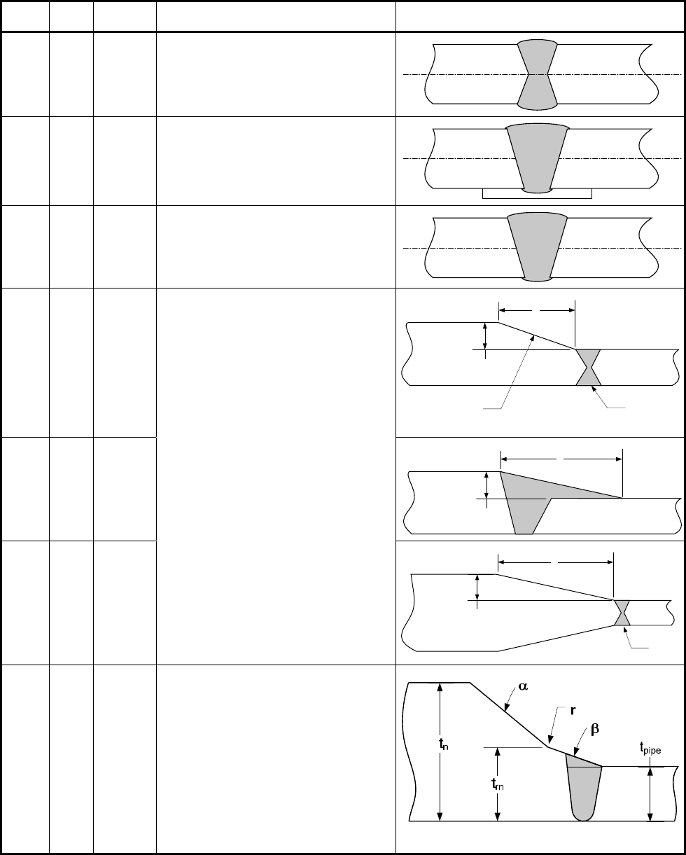
Table 4.2.4 – Some Acceptable Weld Joints For Shell Seams
Detail
Joint
Type
Joint
Category
Design Notes Figure
1 1 A,B,C,D
2 2 B
3 3 B
4 1 A,B,C,D
•
3ab≥
• The length of the taper,
a
, may
include the weld
• Joint Types 2 and 3 may be
permissible, see paragraphs
4.2.5.2 through 4.2.5.6 for
limitations
b
a
Weld
Taper Either
Inside or Outside
5 1 A,B,C,D
6 1 A,B,C,D
a
b
Weld
7 1 B
• The weld bevel is shown for
illustration only
•
1
max 0.8 ,
rn pipe
ttt
⎡⎤
≥
⎣⎦
•
30
α
≤°
•
,14 18.5
β
β
°≤ ≤ °
• r, 6 mm (0.25 in.) min. radius
• Joint Types 2 and 3 may be
permissible, see paragraphs
4.2.5.2 through 4.2.5.6 for
limitations
a
b
标准分享网 www.bzfxw.com 免费下载