ASM Metals HandBook Vol. 8 - Mechanical Testing and Evaluation
Подождите немного. Документ загружается.

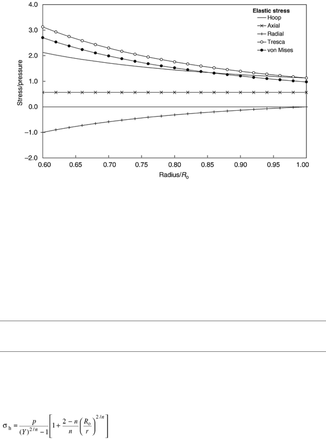
Fig. 2 Distribution of normalized elastic stresses in a pressurized tube with a ratio of inner radius, R
i
, to
outer radius, R
o
, of 0.6
The thicker the tube, the steeper the stress gradient becomes. The radial (compressive) stress on the inside is, by
definition, equal to the inner pressure and gradually decreases to zero towards the outer surface. This radial
stress has to be taken into account when calculating the effective stress. On the other hand, in a thin-walled
tube, the radial stress is often considered negligible, and, therefore, the stress state is simplified to biaxial.
Reference cited in this section
6. R. Seshardi, Design and Life Prediction of Fired Heater Tubes in the Creep Range, J. Pressure Vessel
Technol. (Trans. ASME), Vol 110, Aug 1988, p 322–328
Influence of Multiaxial Stresses on Creep and Creep Rupture of Tubular Components
R.C. Hurst and J.H. Rantala, European Commission, Joint Research Centre, Institute for Advanced Materials (The Netherlands)
Steady-State Creep Stress Distribution in a Tube
The analytical solutions for a tube under steady-state creep (Ref 6, 7, 8) were published first in 1935 by Bailey,
and therefore, the following equations for hoop, axial, and radial stresses are often referred to as the Bailey
equations:
(Eq 17)

(Eq 18)
(Eq 19)
The stress distribution is shown in Fig. 1.
These stresses are related by a correlation, which can be used to check numerical calculations:
σ
a
= 0.5(σ
h
+ σ
r
)
(Eq 20)
With creep, the initial elastic stresses are redistributed and the stresses are “reversed.” Under pressurization, the
maximum elastic stresses appear on the inner surface of the tube, but, due to creep, these stresses relax and,
under steady-state conditions, the maximum stresses move to the outer surface. The maximum initial elastic
hoop stress of 2.13p on the inner surface is reduced to only 1.16p under steady-state creep. Meanwhile, on the
outside, the initial elastic hoop stress of 1.13p increases to 1.76 under creep conditions. It should also be noted
that the elastic stress distribution is a special case of creep stress distribution when n = 1.
References cited in this section
6. R. Seshardi, Design and Life Prediction of Fired Heater Tubes in the Creep Range, J. Pressure Vessel
Technol. (Trans. ASME), Vol 110, Aug 1988, p 322–328
7. R.W. Bailey, Creep Relationships and Their Application to Pipes, Tubes and Cylindrical Parts under
Internal Pressure, Proc. Inst. Mech. Eng. A, Vol 164, 1951, p 425
8. I. Finnie and W.R. Heller, Creep of Engineering Materials, McGraw-Hill, 1959
Influence of Multiaxial Stresses on Creep and Creep Rupture of Tubular Components
R.C. Hurst and J.H. Rantala, European Commission, Joint Research Centre, Institute for Advanced Materials (The Netherlands)
Plastic Stresses in a Tube
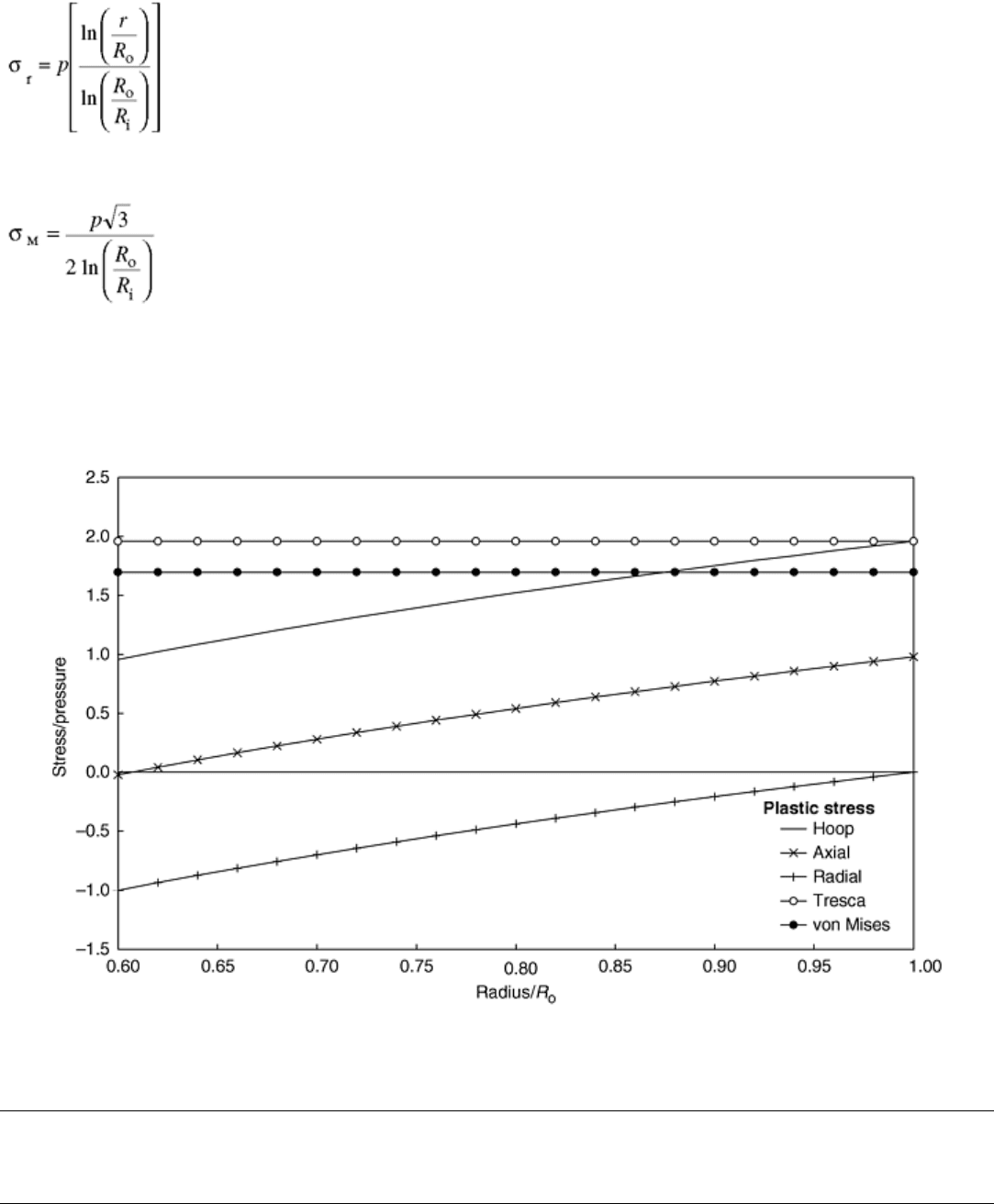
These equations assume a completely plastic case:
(Eq 21)
(Eq 22)
(Eq 23)
A reference stress equal to the von Mises effective stress value can be calculated for the fully plastic case using
Eq 24:
(Eq 24)
The plastic stress distribution for the example tube is shown in Fig. 3. It should be noted that the plastic stress
distribution in a cylindrical body is very similar to the creep stress distribution. This similarity has been used in
the limit load analysis where plastic finite-element (FE) stress analysis is used to determine representative
failure loads for various components. Second, both von Mises and Tresca distributions are constant through the
wall thickness. Third, it should be noted that the Tresca value is equal to the maximum hoop stress value on the
outer surface.
Fig. 3 Distribution of normalized plastic stresses in a pressurized tube with a ratio of inner radius, R
i
, to
outer radius, R
o
, of 0.6
Influence of Multiaxial Stresses on Creep and Creep Rupture of Tubular Components
R.C. Hurst and J.H. Rantala, European Commission, Joint Research Centre, Institute for Advanced Materials (The Netherlands)
Thermal Stresses in a Tube
Often thermal stresses appear in plant components, which can have a significant influence on the stresses. In
heat exchangers, tubes operate continuously under a thermal gradient, and, in many plants, thick-walled
components experience severe thermal gradients, especially during transition periods like start-up and shut-
down of the plant. Often these thick-walled components set a limit to the start-up speed just because of the
maximum allowable thermal stress in the wall.
During operation, thermal stresses are often superimposed on primary stresses originating from the pressure.
The thermal stresses are called secondary because, in long-term operation, they may relax as a result of creep.
In that case, after long-term operation (after complete stress redistribution), the stresses follow the steady state
distribution; at shut-down, the initial elastic stresses and thermal stresses have to be subtracted. Then the
remaining stress at zero pressure with zero temperature gradient becomes:
Remaining stress = steady state stress - elastic stress
from pressure - thermal stress
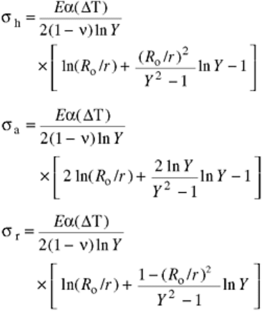
The thermal hoop, axial, and radial stresses can be calculated using the following equations. Here the
temperature gradient has been defined as a result of external heating. For the cases of internal heating
(applicable to the start-up of a cold component), the thermal gradient, ΔT, becomes negative and the stress
distribution is reversed.
(Eq 25)
(Eq 26)
(Eq 27)
where E is the modulus of elasticity and ν is Poisson's ratio. An example of the distribution of multiaxial
thermal stresses is shown in Fig. 4 for the example tube.
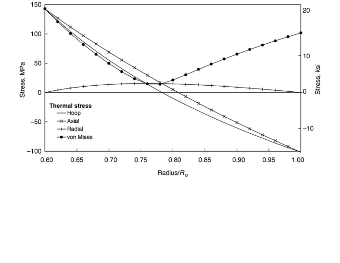
Fig. 4 Distribution of normalized thermal stresses in a pressurized tube with a ratio of inner radius, R
i
,to
outer radius, R
o
, of 0.6 and with a temperature gradient of 50 °C (90 °F) under external heating
Influence of Multiaxial Stresses on Creep and Creep Rupture of Tubular Components
R.C. Hurst and J.H. Rantala, European Commission, Joint Research Centre, Institute for Advanced Materials (The Netherlands)
Comparison of Life Predictions By Different Effective Stress Criterion
Figure 5 contains data generated for P91 steel at 600 °C (1100 °F) using tubular specimens (outside diam 38 ×
2 mm, thinner than the example tube in other figures) under internal pressure and axial end load with different
ratios of hoop and axial stress. It should be noted that all the tests were started with the same initial von Mises
stress. In the same figure, the continuum damage mechanics (CDM) model predictions are shown for three
different multiaxial stress rupture criterion: von Mises, Tresca, and Huddleston.
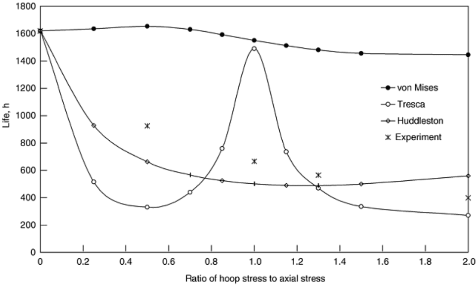
Fig. 5 Multiaxial creep test results for a pressurized P91 tube with end load at 600 °C (1100 °F) under
various ratios of hoop stress to axial stress and with constant initial von Mises stress
One would assume then that the von Mises prediction would be a flat curve, but the CDM model predicts
always a slightly curved shape. Similarly, one would assume that at stress ratios of 2 and 0.5, the life would be
the same, but it does not seem to be the case. The reason for this is that at a stress ratio of 2, the hoop stress is
dominant and the hoop strain leads to an increase of the inner diameter, which will reduce the life in a
pressurized test. On the other hand, at a stress ratio of 0.5 (hoop stress is half of the axial), the axial stress is
dominant and the diameter actually remains constant (the necking as a result of the axial stress is balanced by
the internal pressure). This leads to a slightly increased life.
When the initial von Mises stress is the same in all tests, the shape of the Tresca (or MPS) curve is explained by
the hoop and axial stress components. Figure 6 clarifies this. The MPS in this figure consists of axial stress
between stress ratios 0 to 1 and hoop stress when stress ratio is greater than unity. The MPS life curve in Fig. 5
is a “mirror image” of the MPS curve in Fig. 6.
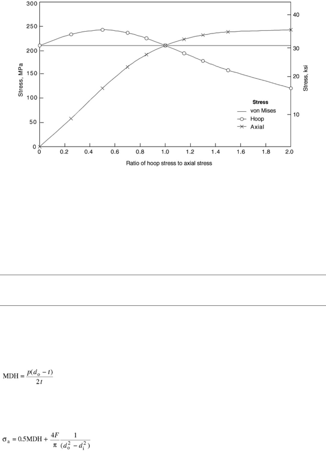
Fig. 6 Hoop and axial strain components in an internally pressurized tube when the von Mises effective
stress is kept constant
The plots like Fig. 5 can be used to tell whether the stress rupture criterion is von Mises or MPS. For many
materials, the experimental points lie somewhere in the middle. It has been observed that the Huddleston stress,
described by, Eq 4 correlates fairly well with this data. It should be noted, however, that plots like Fig. 5 are
time dependent. This figure describes the short-term behavior where the failure is associated with large
deformation. In long-term service, the damage mechanism is constrained grain-boundary cavitation, which is
associated with very little deformation. Therefore, under the long-term service conditions, the creep behavior
tends to become more MPS dominated.
Influence of Multiaxial Stresses on Creep and Creep Rupture of Tubular Components
R.C. Hurst and J.H. Rantala, European Commission, Joint Research Centre, Institute for Advanced Materials (The Netherlands)
Commonly Used Stress Equations for Design
Often, the design of pressurized components is based on simple and desirably conservative design rules, and, in
many cases, a simple mean diameter hoop (MDH) stress equation is used only because experience has proved it
to be conservative in most cases:
(Eq 28)
where d
o
is the outside diameter, and t is the tube thickness. According to Cane (Ref 4), the mean diameter
hoop stress well describes the life at high pressures and underestimates it at low stresses; that is, MDH is
conservative in design for long-term operation.
The axial stress component in a pressurized tube with axial loading can be calculated using the following
equation:
(Eq 29)
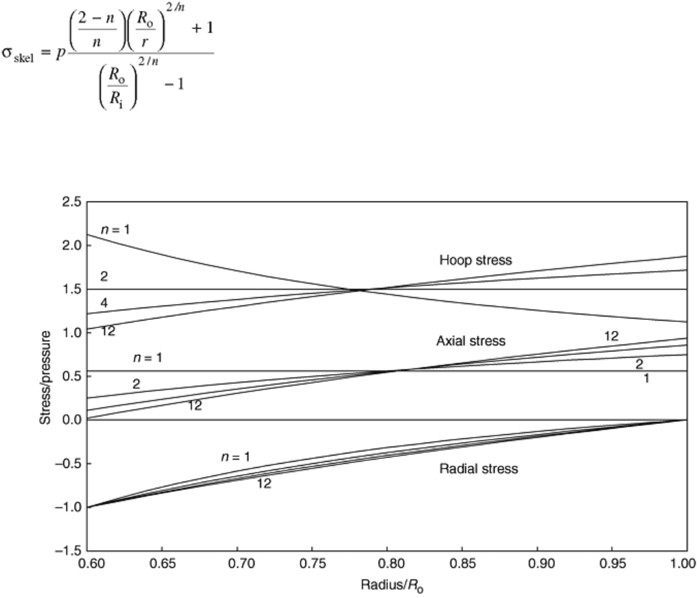
where F is the axial load and d
i
is the inside diameter. These simple stress equations are insensitive to system
(bending) stresses, which may appear, for example, in a piping as a result of thermal expansion between fixed
points. This can result in severe secondary bending stresses, which should be taken into account in piping
design. Omission of bending stresses can lead to premature failure in, for example, welds close to fixed points
(type IV cracking).
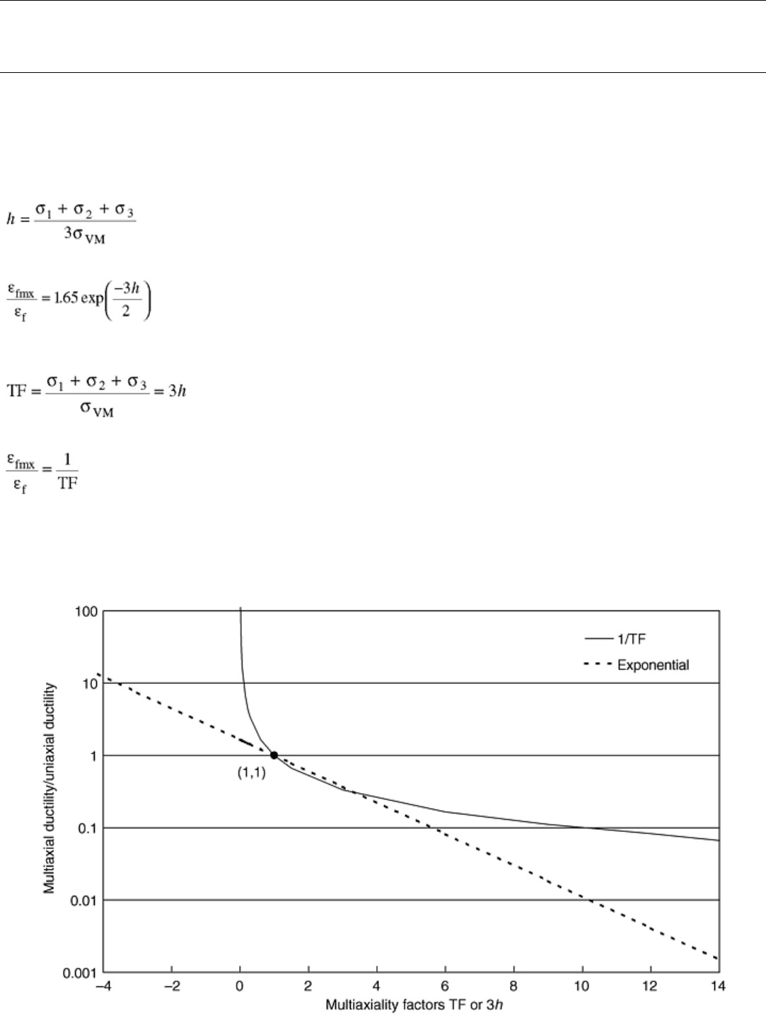
For tubes, a skeletal stress has been found to correlate fairly well with the stress rupture data:
(Eq 30)
The basis for this definition is the observation that in approximately the middle of the wall thickness there is a
point where the stresses are not dependant on the Norton creep exponent, n, as demonstrated in Fig. 7.
Calculation of the von Mises stress in the mid-wall using the steady-state creep stresses leads to Eq 30. The
skeletal stress value for the tube used in the example of Fig. 7 becomes 1.71p.
Fig. 7 Stress distributions in a creeping tube at different creep exponents showing the appearance of a
skeletal stress in a point where the hoop stress value is practically independent of the Norton creep
exponent (n). R
o
, outside radius of tube
Reference cited in this section
4. B.J. Cane, Representative Stresses for Creep Deformation and Failure of Pressurised Tubes and Pipes,
Int. J. Pressure Vessel Piping, Vol 10, 1982, p 119–128
Influence of Multiaxial Stresses on Creep and Creep Rupture of Tubular Components
R.C. Hurst and J.H. Rantala, European Commission, Joint Research Centre, Institute for Advanced Materials (The Netherlands)
Multiaxial Creep Ductility
It is well known that triaxiality has a strong effect on the ductility of materials. Under high degrees of tensile
triaxiality, ductility will decrease remarkably. Therefore, a constraint parameter, h, is introduced (Ref 9):
(Eq 31)
Then the ratio of multiaxial and uniaxial ductility can be expressed by an exponential equation:
(Eq 32)
where ε
f
is failure strain and ε
fmx
is the failure strain under multiaxial conditions. An alternative solution is to
define a triaxiality factor (TF), which is three times the h parameter:
(Eq 33)
Then multiaxial ductility (Ref 10) can then be calculated from a simple formula:
(Eq 34)
These ductility equations give very different predictions of the multiaxial behavior at both extremes. The
reciprocal Eq 34 gives very high values when TF approaches zero (equal tensile principal stresses) and does not
work if TF is negative. The exponential Eq 32 gives lower multiaxial ductility values at small and negative
values of h and is more conservative at high degrees of multiaxiality. Both curves go through the uniaxial point,
which is TF = 1 and h = ⅓(Fig. 8).
Fig. 8 Multiaxial ductility as a function of the triaxiality factor using Eq 32 and 34
High degrees of multiaxiality can be found especially at notch roots or in front of a crack tip. Also, in the soft
zone of the heat-affected zone of a weld there is a strong element of tensile triaxiality, which will have an effect
on the life.
The multiaxial ductility for our model tube (R
i
= 0.6R
o
) gives the values shown in Table 1 when calculated
using the Eq 32 and 34. This result is extremely important because it explains the discrepancy between the two
observations:
• Creep stress analysis for a cylindrical body gives always the maximum effective stress values on the
inner surface of the tube.
• The service experience shows that the creep damage always appears on the outer surface of the tube—at
least for materials other than the most brittle ones.
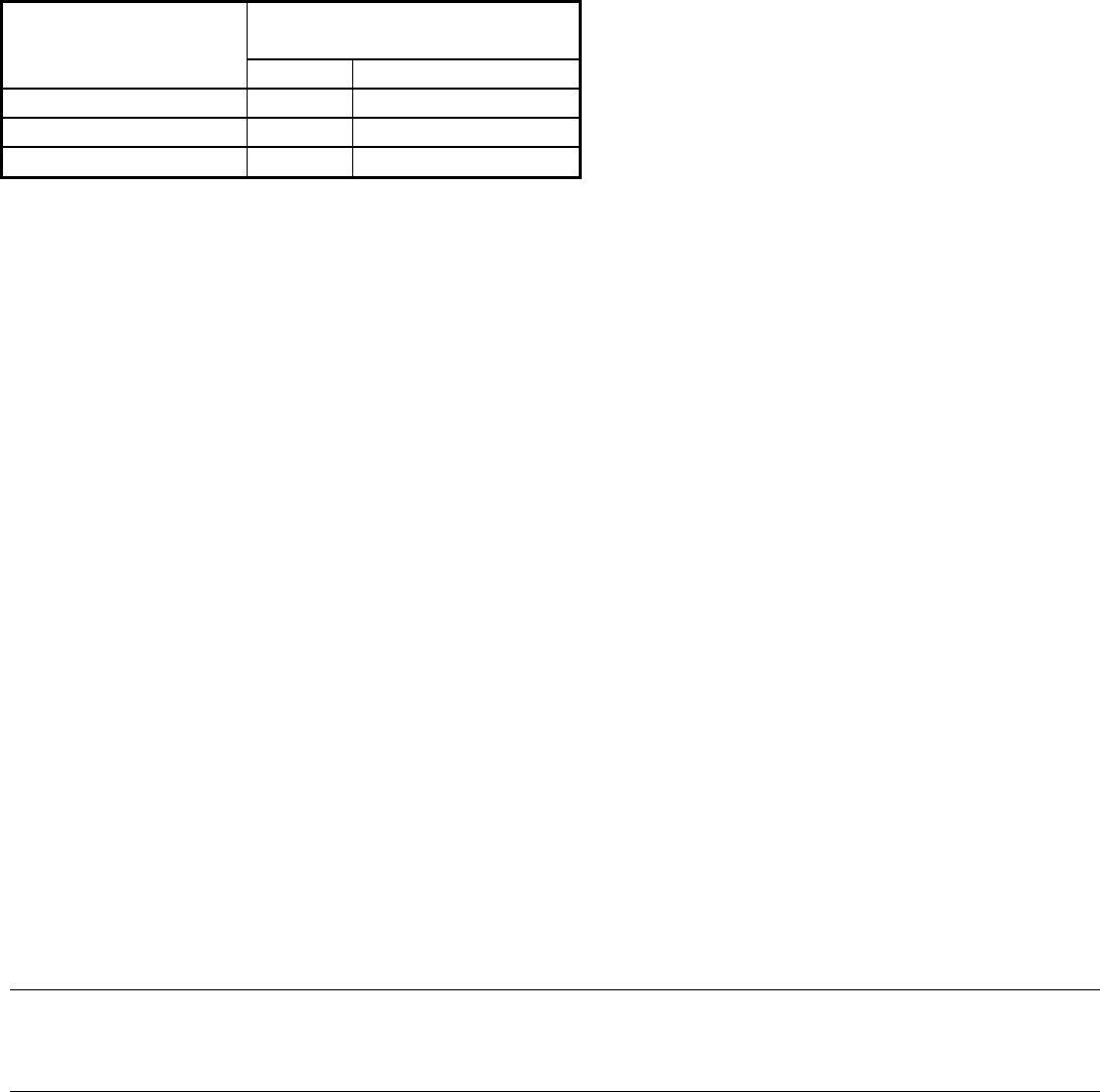
Table 1 Ratio of multiaxial and uniaxial ductility calculated at various locations in the wall of a tube
Ratio of multiaxial ductility to
uniaxial ductility
Location on tube wall
1/TF
(a)
1.65 exp(-3h/2)
(b)
Inner surface 7.60 1.54
Mid wall 1.01 1.00
Outer surface 0.58 0.69
Tube has a ratio of inner radius to outer radius of 0.6.
(a) See Eq 34.
(b) See Eq 32.
In a creeping tube, the strains are proportional to 1/radius. Therefore, both the effective stress and the strain on
the inner surface of the tube are the highest, but the multiaxial ductility is clearly higher than the uniaxial
ductility, as shown in Table 1. This is why the damage does not initiate on the inside of the tube (except in
materials where the uniaxial creep ductility is very low—then the relaxation of the high initial elastic stresses
can cause failure on the inside). On the other hand, according to Eq 32 and 34, the ductility on the outer surface
is much less than the uniaxial ductility, which leads to the initiation of the damage on the outer surface first.
Fortunately, the nature of creep rupture itself seems to simplify the problem of multiaxiality in plant
components. In long-term service, creep rupture occurs with a constrained grain-boundary cavity nucleation
and growth mechanism, it seems to be more MPS controlled, and damage appears predominantly on the outer
surface (which is fortunate from an inspection point of view).
This finding could simplify the necessary engineering calculations of multiaxial stress systems to some extent.
However, the present-day design codes for plant equipment do not necessarily reflect this idea, although design
lives can be well above 100,000 h where MPS would become the controlling parameter. Further, it should be
remembered that for components in the creep regime, the MPS should not be calculated according to the initial
elastic distribution but according to the steady-state creep stress distribution.
References cited in this section
9. P. Segle, P. Andersson, and L.Å. Samuelson, A parametric study of creep crack growth in
heterogeneous CT specimens by use of finite element simulations, Mater. High Temp., Vol 15, 1998, p
101
10. B.W. Roberts, Influence of Multiaxial Stressing on Creep and Creep Rupture, Mechanical Testing, Vol
8, ASM Handbook, ASM International, 1985, p 343–345
Influence of Multiaxial Stresses on Creep and Creep Rupture of Tubular Components
R.C. Hurst and J.H. Rantala, European Commission, Joint Research Centre, Institute for Advanced Materials (The Netherlands)
