Ahsan A. (ed.) Evaporation, Condensation and Heat transfer
Подождите немного. Документ загружается.

Modelling the Thermo-Hydraulic Performance of
Cooling Networks and Its Implications on Design, Operation and Retrofit
199
For every exchanger specify: t’s, T’s,
V’s, ΔP
allowable
, Q, F
T
For the network specify: valve’s, d
pipe’s
, pump
capacity, N
p
, L
t
, d
i
, d
o
Calculate K for valves and pipes
Assume number of tubes (Nta) and
calculate K for heat exchangers
Calculate ΣK
pipe, valve, Cx
for each single branch
Calculate K for network
arrangement and K
overall-system
Calculate ΔP
system
Calculate flow distribution
Specify K
Cx’s-req
= f(ΔP
C
x
allow
, F
hx
) and compare with K
Cx
Calculate t
out’s
= f(Q
Cx-req
, t
in
, V
C
x
)
Calculate temperature correction
factor
Calculate h
t
, h
s
and U
overall
Calculate LMTD’s
Calculate heat transfer
area, A
Cx’s
Calculate number of tubes, Nt
End
Modify
number of
tubes
Nt = Nta
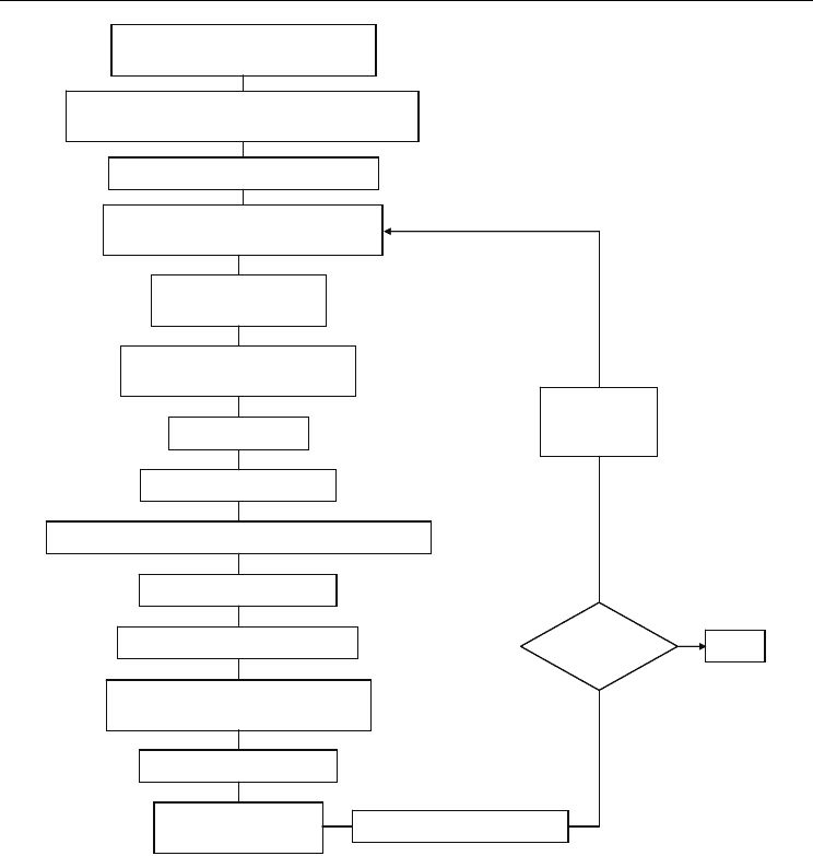
Fig. 6. Algorithm for the thermo-hydraulic design of a cooling network.
6. Case study
Using the principles introduced in the sections above, the design of a flexible cooling system
will be looked at in more detail. A cooling system is designed to operate for a range of plant
throughputs, namely: 120%, 100% and 80%. Heat exchangers are initially designed for the
maximum production rate where the cooling demand is 3.65 MW; cooling water is available
at 20°C and the maximum return temperature is 40°C with a water flow rate of: 0.0438
m3/s. The process information for the streams is given in Table 2. The allowable pressure
drops, water flow rates and the corresponding K values are presented in Table 3. In Table 4
the geometry of the exchangers such as the tube passes, tube length and tube inner and
outer diameter and the K values for the case of water control valves are also given. The

Evaporation, Condensation and Heat Transfer
200
information related to the pipe lengths, diameters, heights and control valves is provided in
Table 5. When the various components of the system are brought together, the cooling water
is redistributed which in turn affects the thermal performance of the exchangers. So, the new
water distribution is determined and the results are given in Table 6. The calculated
pressure drops through branches are shown in Table 6.
Stream
Inlet
temperature (°C)
Outlet
temperature (°C)
CP
(W/°C)
Heat duty
(kW)
H1 50 30 8 400
H2 50 40 42.53 1,014
H3 85 40 16.8 1,906
H4 85 65 4.24 205
C1 20 40 5.14 400
C2 20 40 12.85 1,014
C3 20 40 23.13 1,906
C4 20 40 2.57 205
Table 2. Stream process data.
Exchanger
ΔPallowable
(kPa)
Water flow rate
(m3/s)
K
Cx1 40 0.0052 285,239
Cx2 40 0.0129 330,432
Cx3 40 0.0232 117,771
Cx4 40 0.0026 6,162,219
Table 3. Pressure drop, water flow rate and K values for heat exchangers.
Exchanger Cx1 Cx2 Cx3 Cx4
K valve 9 9 9 9
No. Passes 2 2 2 2
length, m 6.1 6.1 6.1 6.1
tube i.d., m 0.0148 0.0148 0.0148 0.0148
tube o.d., m 0.01905 0.01905 0.01905 0.01905
Table 4. Geometrical parameters of heat exchangers.
Branch
Diameter
(m)
Length
(m)
Heigh
(m)
Kvalve
Feed 0.35 220 0 9
A 0.25 120 5 9
B 0.25 170 7 9
C 0.2 180 10 9
D 0.2 190 10 9
Return 0.35 220 0 55
Table 5. Geometry and dimensions of the various components of the piping system.

Modelling the Thermo-Hydraulic Performance of
Cooling Networks and Its Implications on Design, Operation and Retrofit
201
Branch
Water flow rate
(m3/s)
Pressure drop
(kPa)
A 0.0020 40.03
B 0.0186 42.19
C 0.0112 41.95
D 0.0121 42.30
Total flow rate 0.0438
Table 6. Water flow rate re-distribution through branches.
Under these conditions, the design of the heat exchangers has to be revisited and new
dimensions determined for each exchanger. What is sought is that each exchanger removes
the required heat load; on achieving this target, the water outlet temperature in some cases
goes above the established limit of 40°C. The relation between surface area and K values can
be seen in Tables 3 and 7; exchanger Cx3 has the largest surface area and the lowest K value,
the opposite applies to exchanger Cx4 that exhibits the smallest surface area and largest K
value.
Cx1 Cx2 Cx3 Cx4
t
out
(°C) 27.92 41.70 44.43 44.91
ΔP (kPa)
40.00 40.00 40.00 40.00
Surface Area (m2) 130 110 196 14
No. of tubes 356 301 537 37
Table 7. Revisited geometry of heat exchanger for the final water flow rate distribution.
The thermo-hydraulic model described in this work is used to demonstrate the flexible
operation of the cooling system; for the various scenarios the process stream flow rates are
multiplied by the required factors to simulate the increase or reduction in production rate.
The network presented in Figure 1 is used as case study. Tables 8, 9 and 10 show the
network water flow rates and temperatures for 120%, 100% and 80% throughput
respectively.
Water
temperatures (°C)
Process
temperatures (°C)
Branch
Inlet Outlet Inlet Outlet
Total tower
cooling load
(MW)
Cooling
water
(m
3
/s)
System
bypass
(m
3
/s)
A 20 28.29 50 29.05 0.0121
B 20 41.72 50 39.9 0.0111
C 20 45.6 85 37.7 0.0186
D 20 45.6 85 64.5
3.65
0.0020
0.0
Water return
temperature
39.8
Water
flow
rate (m
3
/s)
0.0438
Table 8. Water flow rate distribution and stream temperatures for a 120% plant throughput.

Evaporation, Condensation and Heat Transfer
202
Water
temperatures (°C)
Process
temperatures (°C)
Branch
Inlet Outlet Inlet Outlet
Total tower
cooling load
(MW)
Cooling
water
(m
3
/s)
System
bypass
(m
3
/s)
A 20 30.4 50 28.9 0.0081
B 20 43.9 50 41.17 0.0074
C 20 50.15 85 40.6 0.0124
D 20 52.7 85 64.06
2.85
0.0013
0.0146
Water return
temperature
43.2
Water
flow rate
(m
3
/s)
0.0292
Table 9. Water flow rate distribution and stream temperatures for a 100% plant throughput.
Since the scenarios that are analyzed consider seasonal variations in plant production, it is
acceptable to consider that instead of just recycling water back to the cold pond, pumps can
be taken out of operation for 100% and 80% plant throughput. For instance, six pumps can
be selected for the condition of 120%. When production returns to 100%, one pump is taken
out of operation. Further decrease in throughput to 80% is accompanied by the shutting
down of a second pump.
Water
temperatures (°C)
Process
temperatures (°C)
Branch
Inlet Outlet Inlet Outlet
Total tower
cooling load
(MW)
Cooling
water
(m
3
/s)
System
bypass
(m
3
/s)
A 20 32.9 50 29.51 0.005
B 20 45.6 50 42.59 0.0046
C 20 55.07 85 44.39 0.0078
D 20 61.16 85 64.34
2.05
0.0008
0.0256
Water return
temperature
46.82
Water
flow rate
(m
3
/s)
0.0182
Table 10. Water flow rate distribution and stream temperatures for a 80% plant throughput.
7. Determining the performance under changed cooling water temperature
Flexible operation can be extended to situations where the ambient conditions affect the
performance of a cooling tower; for instance: variation in the wet bulb temperature. The
model is used to simulate the case study given in Table 2. The simulation proceeds by
assuming a change in the inlet temperature of the cooling water; the effect upon the outlet
temperatures is determined and then the water flow rate is changed in order to restore the
process stream target temperatures.
Table 11 shows the case where the inlet temperature is 24°C and 18°C respectively. When
the temperature of the cooling water increases to 24°C, the simulation shows that increasing
the water flow rate by 8%, the process outlet temperatures can be restored to acceptable
values as shown in Table 12.

Modelling the Thermo-Hydraulic Performance of
Cooling Networks and Its Implications on Design, Operation and Retrofit
203
The water return temperature for this case is 35.49°C and the cooling load 3.47 MW. Now,
for the case where the cooling water enters at 18°C to the system, the heat removal rate will
be higher than required. Therefore, the solution consists in reducing the flow rate. Table 13
shows the thermal performance of the exchangers; the cooling duty for this case is 3.53 MW
and the water return temperature is 41.4°C. Since the performance is within acceptable
values, the system needs not to adjust its water flow rate.
Cooling water: 24°C Cooling water : 18°C
Unit Tout (°C) tout (°C) Unit Tout (°C) tout (°C)
Cx1 31.85 31.18 Cx1 27.66 26.84
Cx2 41.32 42.82 Cx2 39.32 41.16
Cx3 41 48.06 Cx3 36.32 44.42
Cx4 65.65 48.22 Cx4 63.75 44.6
Table 11. Temperature response at different cooling water inlet temperatures.
Cooling water: 24°C
Unit
Process stream
Tout (°C)
Process stream
Target (°C)
Cooling water
tout (°C)
Cx1 31.4 30 30.4
Cx2 40.6 40 41.87
Cx3 39.1 40 46
Cx4 65 65 46
Table 12. Process outlet temperatures after increasing water flow rate by 8%.
Cooling water: 18°C
Unit
Process stream
Tout (°C)
Process stream
Target (°C)
Cooling water
tout (°C)
Cx1 28.48 30 28.4
Cx2 40.6 40 42.85
Cx3 39.33 40 48
Cx4 64.93 65 48.6
Table 13. Thermal performance after reduction of cooling water temperature.
8. Conclusions
Cooling systems are, in most applications, designed for a maximum fixed heat duty and
its operation remains unchanged despite the variations in plant throughput. A
disadvantage of this practice is that operating costs tend to be higher than they should be.
Flexible operation is the capacity of the system to deliver the required heat load within
some specific bounds. For instance, specific bounds may be the following: plant
throughput may vary between a minimum and a maximum from normal production rate
and the wet bulb temperature, which significantly affects the performance of a cooling
tower, experiences changes between seasons. When a temperature or flow rate

Evaporation, Condensation and Heat Transfer
204
disturbance enters a cooling system, it propagates around until the steady state is reached.
Since the steady state response of a cooling system is independent of the actual
arrangement of the coolers then the heat load removal can be controlled through the use
of a bypass scheme. With the operation of a flexible cooling system, the pumping power
consumption is a variable that can also be controlled. Typically, the design of a cooling
system is carried out by considering individual components at a time for a given set of
operating conditions; when these components are placed together into a system, the water
flow rate is no longer the same since it tends to re-distribute through the network
depending on the resistance it encounters. The result of this phenomenon is that water
flow rate distributes through the network so that the pressure drop in all branches of the
system equates. So, a thermo-hydraulic model has to be implemented for the
determination of the performance of a cooling system and it can be used to produce a
design that meets the required flexibility. Such a model has been introduced in this work.
9. Nomenclature
A heat exchanger surface area [m
2
]
Cr heat capacity mass flow rate ratio
C number of coolers in cooling network
CP
min
minimum heat capacity mass flow rate
CP
max
maximum heat capacity mass flow rate
d diameter [m]
h heat transfer coefficient [kJ/m
2
°C]
F
T
logarithmic temperature correction factor
K loss coefficient
Lt tube lengths [m]
M number of mixing point in a cooling network
Nt number of tubes in heat exchanger
Nta number of tubes assumed
NP number passes
NTU number of heat transfer units
NV number of temperature variables in a cooling network
Q heat load [kW]
S number of streams
T hot stream temperature [°C].
t cold stream temperature [°C]
U overall heat transfer coefficient [W/m
2
°C]
u fluid velocity [m/s]
V volumetric flow rate [m
3
/s]
Subscripts
s shell side
t tube side
i inner condition
o outer condition
Superscripts
N
new condition

Modelling the Thermo-Hydraulic Performance of
Cooling Networks and Its Implications on Design, Operation and Retrofit
205
o original condition
m mixing point
Greek letters
ε thermal effectiveness
ΔP pressure drop (kPa)
ρ density [kg/m3]
10. References
Bernier M A (1994). Cooling tower performance: theory and experiments. ASHRAE
Transactions Research : 114 – 121.
Castro M M, Song T W, Pinto J M (2000). Minimization of operational costs in cooling water
Systems. Trans IchemE 78: Part A : 196 – 201.
Chengqin R (2006). An analytical approach to the heat and mass transfer processes in
counterflow cooling towers. Journal of Heat Transfer Transactions of the ASME
128: 1142 – 1148.
EI – Dessouky H T A, AI – Haddad A A, I–Juwayhel F A (1997). Modified analysis of
counter flow wet cooling towers. Journal of Heat Transfer Trans of ASME 119: 617 –
626.
Gharagheizi F, Reza H and Shohreh F (2007). Experimental study on the performance of
mechanical cooling tower with two types of film packing. Energy Conversion and
Management 48: 277 – 280.
Giorgia F, Cortinovis M, Ribeiro T, Paiva J L, Tah S W, Pinto J M (2009). Integrated analysis
of cooling water systems: modeling and experimental validation. Applied Thermal
Engineering 29: 3124–3131.
Jaber H T, Webb R T (1989). Design of cooling towers by the effectiveness – NTU method.
ASME Journal of Heat Transfer 11: 873–843.
Jameel–Ur– Rehman K, Bilal A Q and Syed M Z A (2004). Comprehensive design and
performance evaluation study of counter flow wet cooling towers. International
Journal of Refrigeration 27 : 914–923.
M. Picón Núñez, J. Castro Páez and F. Vizcaíno García (2002). Steady state simulation for the
de-bottlenecking of heat recovery networks. Applied Thermal Engineering 22 :
1673-1687.
Majozi T, Moodley A (2008). Simultaneous targeting and design for cooling water systems
with multiple cooling water supplies. Computers and Chemical Engineering 32:
540–551.
Nenad M, Pertti H (2001). A comprehensive approach to cooling tower design. Applied
Thermal Engineering 21: 899 – 915.
Panjeshahi M H, Ataeib A, Gharaiec M, Parandc R (2009). Optimum design of cooling water
systems for energy and water conservation. Chem Eng Res Des 8: 7 , 200–209.
Perry and Cecil H. Chilton (1999). Fluid particle dynamics. Chemical Engineer’s Handbook,
McGraw Hill.
Picón-Núñez M, Nila-Gasca C, Morales-Fuentes A (2007). Simplified model for the
determination of the steady state response of cooling systems. Applied Thermal
Engineering 27:1173–1181.

Evaporation, Condensation and Heat Transfer
206
W.M. Kays and A.L. London (1984). Compact heat exchangers, Third edition, McGraw
Hill.

10
Heat Exchange in Furnace Side Walls with
Embedded Water Cooled Cooling Devices
Gabriel Plascencia
CIITEC –IPN México, D.F.,
México
1. Introduction
Current copper (as well as nickel and lead) smelting and converting are characterized by
high intensity and productivity. However, this has lead to increasing demands on
refractories resulting in possible shortening of the service life of furnace linings. To
counteract this, several cooling systems have been designed and implemented in many
copper and / or nickel making facilities (Hatch & Wasmund, 1974; Legget & Gray, 1996).
The different cooling systems can be grouped according to their ability to remove heat from
the hearth of the furnace as shown in Table 1. Cooling systems that are embedded into the
furnace refractory lining are able to extract more energy (10 ~ 100 kW/m
2
) than those acting
on the furnace outer shell (~ 1 kW/m
2
); this main difference is due to the thermal resistance
that the insulating refractory lining offers (Legget & Gray, 1996).
System Location
Heat Flux
(kW/m
2
)
Applications Pros Cons
Plate
coolers
Internal 10 – 30
Stack region of iron
blast furnaces /
flash smelters
High intensity
cooling,
supports lining
Water leaks,
limited by
structural
considerations
Staves Internal 20 – 30
Stack region of iron
blast furnaces
Applicable in
thin wall
sections
Limited control,
expensive
Internal
jackets
Internal 10 – 30
Flash and electric
furnaces
Cheaper than
plates
Water leaks,
uneven cooling
Panels Internal > 30
Electric furnaces,
Vanyukov bath
smelting, Zn
fuming
No refractory
needed, high heat
fluxes
Water leaks,
develop
mechanical stresses
External
jackets
External 5 – 15
Temporary cooling
for overheated
walls
No need to shut
down
Limited heat flux
in thick sections
Spray
cooling
External 5 – 15
Electric and flash
furnace reaction
shaft
Cheap, no need to
shut down
Corrosion in the
outer shell, limited
heat flux
Air
cooling
External < 10
Underneath of
many furnaces
Cheap,
water free
Very low heat
fluxes
Table 1. Cooling systems industrially available, after Legget and Gray (Legget & Gray, 1996)
Evaporation, Condensation and Heat Transfer
208
Another factor that affects the difference in the heat flux removal is that the systems that are
embedded in the refractory are closer to the furnace’s hot face, reducing the effective heat
transfer distance, thus increasing the ability to remove heat.
Proper cooling system design is necessary since not every smelter runs in the exactly same
manner, as an example, if the side wall heat flux is too low, the refractory may wear back, or
if the cooling is highly intense, the excessive cooling may lead to higher heat losses.
Modern smelting processes such as flash, bath or electric furnace, make external cooling
unsuitable for their implementation, instead embedded systems are required due to their
capacity to extract more heat and thus protect the refractory walls.
Hatch and Wasmund (Hatch & Wasmund, 1974) recognized that refractories are attacked by
several mechanisms, such as melting, dissolution by molten metal/slag, chemical reactions
between the refractory and the slag. They also acknowledged that refractory spalling may
happen as a result of thermal cycling and also tapping and charging operations may
promote refractory erosion due to the collision of the charging materials with the lining.
Another problem related to the lining wear is the penetration of molten material into cracks
or joints. Thermal cycling not only induces stresses into the lining they also promote the
freezing and re-melting of the material deposited on the cracks, enlarging them to a point
where leaking of the molten material may produce run outs.
The major operational problems associated with embedded cooling systems are:
• Water leaking through the refractory lining, which in the worst case scenario may result
in catastrophic explosions due to the contact of cooling water with the molten metal. It
also may happen that the leaked water reacts with the process gas (especially SO
2
),
resulting in corrosion of the cooling devices, reducing their ability to extract heat.
• Uneven control of the wall heat transfer resulting in either increased refractory wear or
heat losses
• Air gaps formed as a result of the thermal cycles experienced by the furnace or due to
manufacturing problems of the cooling devices, causing loss of the cooling efficiency.
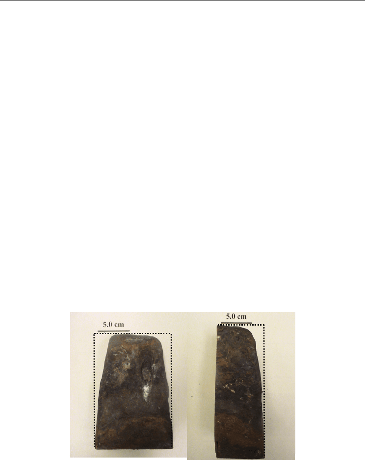
(a)
(b)
Fig. 1. Hot end of water cooled copper finger after being removed from a flash furnace. (a)
Front view, (b) lateral view. The dotted lines represent the original dimensions of the cooler.
Merry et al (Merry et al., 2000) offer similar data on the amount of heat that can be removed
with different cooling systems. Notice that in this compilation Merry et al, include finger
coolers. These cooling devices are in the mid range in terms of heat removal, they account