Ahsan A. (ed.) Evaporation, Condensation and Heat transfer
Подождите немного. Документ загружается.

9
Modelling the Thermo-Hydraulic Performance of
Cooling Networks and Its Implications on
Design, Operation and Retrofit
Martín Picón-Núñez, Lázaro Canizalez-Dávalos and Graham T. Polley
Department of Chemical Engineering, University of Guanajuato,
México
1. Introduction
The set of heat transfer equipment through which heating and cooling takes place within a
process is known as the heat exchanger network. Heat exchanger networks are made up of
three main subsystems: a) the heating network, where thermal energy from external sources
is supplied to a process, b) the heat recovery network, where thermal energy available
within a process is recovered in order to minimize the external energy consumption, and c)
the cooling network, where the low grade thermal energy from a process is rejected to the
environment. A cooling network is an essential part of a cooling system; its design,
operation and retrofit is looked at in this chapter.
The main components of a cooling system are the set of coolers or cooling network, the cooling
system and the flow system which includes the pumping system and the pipeline. All the
components of a cooling tower are linked and failure to appreciate this relation may lead to
operating difficulties and excessive operating costs. In this chapter we look in detail at the
interaction between these three components in the light of a thermo-hydraulic model.
The thermal analysis is based on the application of the thermal effectiveness model originally
developed for single heat exchangers. On the hydraulic side, the water distribution through
the network depends on the pressure drop across the various branches that make up the
network; this in turn has implications on the thermal performance of the coolers.
During operation cooling systems are subject to changes in operating conditions that affect
their heat removal capacity. These changes take place as a result of any of the following: plant
throughput variations during the year; variations in ambient conditions that affect the
performance of cooling towers; the performance of heat exchangers gets deteriorated over time
due to fouling, etc. In practice, a cooling systems is commonly designed for point conditions;
normally these point conditions correspond to the case where the whole system is well
overdesigned. One problem with this practice is that the operating costs are much higher than
they should be. This problem can be addressed by the proper application of a thermo-
hydraulic model. In this context, this chapter shows the way a thermo-hydraulic model for
cooling systems is developed and introduces its application in design.
Cooling systems are normally designed for fixed conditions; for instance, they are specified
by a given cooling load, water flow rate, pumping capacity and heat transfer surface area in
Evaporation, Condensation and Heat Transfer
190
coolers. Over design in all of these components is a common practice in industrial
applications; such practice guarantees that the cooling utility is always available regardless
of the expenditure of power. Under such circumstances, it is common to find that the
operation of the cooling system remains unaltered even when plant throughput changes;
however, one consequence of this mode of operation is the rise in operating costs due to
pumping. The way to keep pumping power consumption at a minimum is by means of a
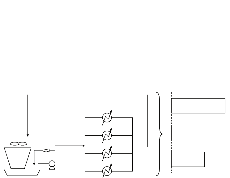
flexible cooling system. A flexible cooling system is one that is able to adapt to the process
heat removal demands as the plant throughput varies; such a systems is depicted in Figure
1; in this diagram, the cooling duty is represented by the length of the rectangles. Three
different situations are shown: a) cooling duty for 100% throughput, b) cooling duty for for
reduced throughput and c) cooling duty for for increased throughput.
A
B
C
D
T
in
T
out
T
w, return
T
w
Heat Load
Reduced
Throughput
Increased throughput
100%
Throughput
A
B
C
D
T
in
T
out
T
w, return
T
w
Heat Load
Reduced
Throughput
Increased throughput
100%
Throughput
Fig. 1. Flexible cooling water system designed to supply the required heat load for changed
plant throughput.
A cooling tower is one of the main thermal components of a cooling system; since in the
operation of these types of units atmospheric air is used to cool down hot water, its thermal
performance is strongly affected by the ambient conditions such as: wet bulb temperature
and air relative humidity (Castro et al., 2000). The need then arises for a model that allows a
quick and reliable determination of the thermal performance of cooling systems when they
are subject to changed operating conditions.
The experimental and theoretical investigation of the thermal performance of cooling towers
has drawn the attention of many researchers either experimentally or theoretically (Bernier,
1994; Jameel-Ur-Rehman et al., 2004; Gharagheizi et al., 2007; Chengqin, 2006; Nenad,
2001). Expressions to apply the thermal effectiveness method directly to cooling towers
were developed by Jaber and Webb (1989). A more detailed and rigorous expression for
the thermal effectiveness applied to cooling towers was presented by El–Dessouky et al.
(1997). The calculation of the rigorous thermal effectiveness takes into consideration the
ratio of the tangent to the enthalpy curve in two points: the midpoint between the tower
inlet and outlet temperatures and the midpoint between the water outlet temperature and
the wet bulb temperature. The thermal effectiveness model can be extended to determine
the overall thermal effectiveness of a network of coolers. Cooling systems as integrated
structures have also been studied either for design, improved operation and
debottlenecking and water conservation (Giorgia et al., 2009; Majozi & Moodley,2008;
Panjeshahi et al., 2009).

Modelling the Thermo-Hydraulic Performance of
Cooling Networks and Its Implications on Design, Operation and Retrofit
191
The work by Picon-Nuñez et al. (2007) shows such application where they demonstrate
that the thermal response of a network of coolers subject to changes in operating
temperatures is independent of the structure. This finding, along with the concept of
flexible design of single heat exchangers becomes the basis for undertaking the design of
flexible cooling systems.
2. Hydraulic model
It has been shown that the pressure loss due to valves and fittings is proportional to the
fluid velocity raised to an exponent. In the turbulent region, this exponent varies between
1.8 and 2.1. However, in the majority of practical cases the pressure drop is calculated as a
function of the square of the velocity.
In the case of water distribution systems, it can readily be demonstrated that the pressure
drop through heat exchangers, valves and fittings can be related to volumetric or mass flow
rate by means of equation (1):
2
ΔP=KV (1)
Where ∆P is the pressure drop, K is a loss constant and V is the volumetric flow rate. The
term V can be expressed as a function of the fluid velocity and the flow area as:
V=uA (2)
Where u is defined as:
2
V
u=
π
d
⎛⎞
⎜⎟
⎝⎠
(3)
The pressure drop through a straight pipe can be expressed as:
2
l
ΔP=2f ρu
d
⎛⎞
⎜⎟
⎝⎠
(4)
Where f is the friction factor, l is the pipe length, d is the pipe diameter and u is the fluid
velocity. Substitution of equation (3) into equation (4) gives:
2
2
lV
ΔP=2fρ
d
πd
⎛⎞
⎛⎞
⎜⎟
⎜⎟
⎝⎠
⎝⎠
(5)
From equation (5), the loss term (K) is defined as:
2
2
l1
K=2fρ
d
πd
⎛⎞
⎛⎞
⎜⎟
⎜⎟
⎝⎠
⎝⎠
(6)
The advantage of using the volumetric flow rate instead of velocity in the determination of
the pressure drop is that it remains constant as the fluid flows through the various
components. In a typical cooling system branch the minimum components are: valves,
pipeline and heat exchangers; so, application of Equation (1) to these components leads to:
Evaporation, Condensation and Heat Transfer
192
2
valve valve
ΔP=KV (7)
2
pipe pipe
ΔP= K V (8)
2
Ex Ex
ΔP=KV (9)
Equation (9) represents an alternative way of determining the pressure drop through heat
exchangers as a function of the volumetric flow rate. The determination of the value of K for
a heat exchanger requires an iterative approach where the geometry that meets the pressure
drop for the given flow rate is sought.
A cooling network is made up of a series of branches each one containing the same elements
mentioned above. Overall, the various branches that constitute a cooling network can be
arranged in parallel, series or a combination of both.
One of the main factors that affect the thermal and hydraulic performance of a cooling
network is the way water flow rate is distributed. For instance, branches located at a given
altitude will carry less water than a similar branch located at a ground level. In the same
way, as the total flow resistance increases in a branch the water flow rate reduces. The
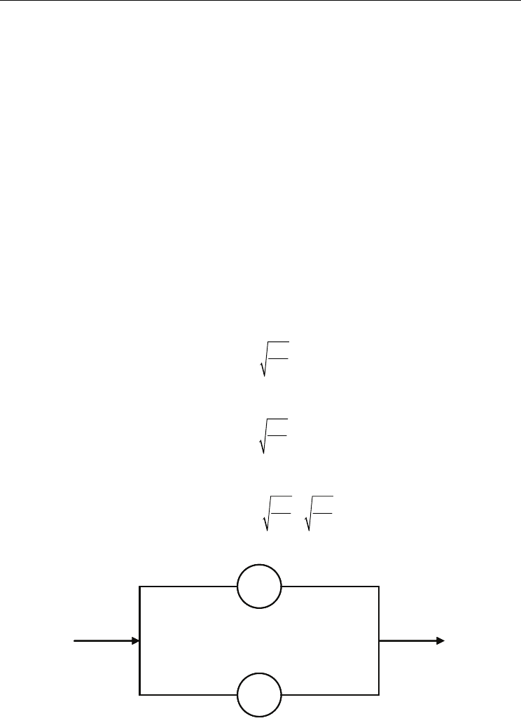
pressure drop through the various branches arranged in parallel that make up a cooling
system is always the same (Figure 2). The water flow rate per branch can be calculated from:
A
A
ΔP
V=
K
(10)
and
B
B
ΔP
V=
K
(11)
Now, the total flow rate is obtained from:
AB
AB
ΔP ΔP
V=V +V = +
KK
(12)
A
B
A
B
Fig. 2. Schematic of a two branch cooling network arranged in parallel.

Modelling the Thermo-Hydraulic Performance of
Cooling Networks and Its Implications on Design, Operation and Retrofit
193
The value of K for the whole system in Figure 2 is given by equation (13) where the terms K
A
and K
B
represent the resistances involved in each branch (pipeline, valves, fittings and heat
exchanger):
A+B
22
AB
ΔP1
K= =
V
11
+
KK
⎛⎞
⎜⎟
⎜⎟
⎝⎠
(13)
For the case of piping, the
K loss term is a function of the velocity whereas for valves and
fittings its value is independent of it. The values of
K for pipe fittings are given in Table 1.
3. Thermal model
The exchanger thermal effectiveness (ε), represents the ratio of the actual heat load to the
maximum load that can thermodynamically be transferred. From this definition it can be
shown that the exchanger thermal effectiveness can be represented by the ratio of the
temperature change that the stream that exhibits the CP
min
undergoes to the maximum
temperature difference that exists between streams. The CP
min
stream is the one whose
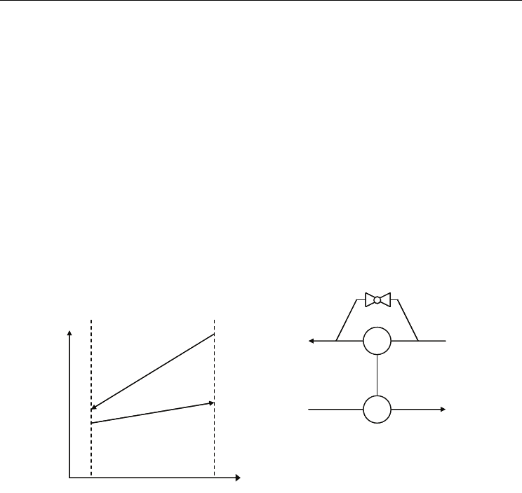
product heat capacity-mass flow rate is the lower of the two. For the temperature profiles
shown in Figure 3, it can be shown that the expression for the thermal effectiveness
according to the definition above is given by:
12
11
T-T
ε =
T-t
(14)
The exchanger thermal effectiveness can also be expressed as a function of Cr
(Cr=CP
min
/CP
max
), the number of heat transfer units (NTU) and the exchanger flow
arrangement. Expressions that relate these terms for a number of flow arrangements have
been developed (Kays & London, 1984). For instance, for a one tube pass and two tube
passes shell and tube heat exchanger, the expression that relates: ε, NTU and Cr is:
()
()
()
-1
1
2
2
r
1
2
2
rr
1
2
2
r
1+exp -NTU 1+C
ε = 2 1+C + 1+C
1-exp -NTU 1+C
⎧
⎫
⎡
⎤
⎛⎞
⎪
⎪
⎢
⎥
⎜⎟
⎜⎟
⎪
⎪
⎢
⎥
⎝⎠
⎨
⎬
⎢
⎥
⎛⎞
⎪
⎪
⎢
⎥
⎜⎟
⎪
⎪
⎜⎟
⎢
⎥
⎝⎠
⎣
⎦
⎩⎭
(15)
The number of heat transfer units is defined as:
min
U A
NTU =
CP
(16)
Where U is the overall heat transfer coefficient and A is the heat transfer surface area. From
the heat balance equation it can be shown that:
min
21
r
max 1 2
CP
t-t
C= =
CP T - T
(17)

Evaporation, Condensation and Heat Transfer
194
Type of fitting or valve
Loss coefficient
(K)
Type of fitting or valve
Loss coefficient
(K)
45º elbow, standard 0.35
Plug disk, open
9.0
45º elbow, long radius 0.2
¾ open
13.0
90º elbow, standard 0.75
½ open
36.0
Long radius 0.45
¼ open
112.0
Square or miter 1.3
Angle valve, open
2.0
180º bend, close return 1.5
Y or blowoff valve,
open
3.0
Tee, standard, along
run, branch blanked off
0.4
Plug cocks, θ=5º
0.05
Used as elbow, entering
run
1 10º 0.29
Used as elbow, entering
branch
1 20º 1.56
Branching flow 1.0 40º 17.3
Coupling 0.04 60º 206.0
Union
0.04
Butterfly valve, θ = 5º
0.24
Gate valve, open
0.17 10º 0.52
¾ open
0.9 20º 1.54
½ open
4.5 40º 10.8
¼ open
24.0 60º 118.0
Diaphragm valve, open 2.3 Check valve, swing 2.0
¾ open 2.6 Disk 10.0
½ open 4.3 Ball 70.0
¼ open 21.0 Foot valve 15.0
Globe valve, bevel seat,
open
6
Water meter, disk
7.0
½ open 9.5 Piston 15.0
Composition seat, open 6.0
Rotary (star-shaped
disk)
10.0
½ open 8.5 Turbine wheel 6.0
Table 1. Loss coefficient for pipe fittings (Perry & Chilton, 1999).
Modelling the Thermo-Hydraulic Performance of
Cooling Networks and Its Implications on Design, Operation and Retrofit
195
From equation (14) it can readily be shown that the outlet temperature of the
CP
min
is given by:
()
21 11
T=T-ε T-t (18)
And combining equation (14) and (17) we have for the outlet temperature of the
CP
max
stream:
()
21 11
t=t+C ε T-t
(19)
A closer look at equation (15) indicates that the thermal effectiveness is a function of C
r
and
NTU; when a temperature change enters a heat exchanger, this change does not have an
effect upon the value of
C
r
or the value of NTU, so the thermal effectiveness remains
unchanged. However, when mass flow rate changes, this has an effect upon the overall heat
transfer coefficient which in turn affects the value of NTU , the value of
C
r
and therefore
affects the thermal effectiveness. So, the thermal effectiveness changes and it has to be
updated for the new exit temperatures to be determined. In the case of coolers, the
temperature rise of water is normally kept low due to fouling problems; so large flow rates
are normally handled making this stream in the majority of cases, the
CP
max
stream. So,
equation (19) can be used to determine the cold stream outlet temperature.
T
H
T
1
T
2
t
1
t
2
T
1
t
2
T
2
t
1
T
H
T
1
T
2
t
1
t
2
T
1
t
2
T
2
t
1
Fig. 3. Temperature profile for a heat transfer between two streams.
For the case of shell and tube heat exchangers, heat transfer coefficients can be updated as
the water flow rate changes using the expressions below:
N 0.8 o
tube tube tube
h=F h (20)
and
N0.6o
shell shell shell
h=F h (21)
Where the terms F
tube
and F
shell
, represent the ratio of the original mass flow rate to the new
mass flow rate; h is the heat transfer coefficient and the superscripts (
o) and (
N
) indicate the
original and new condition respectively.
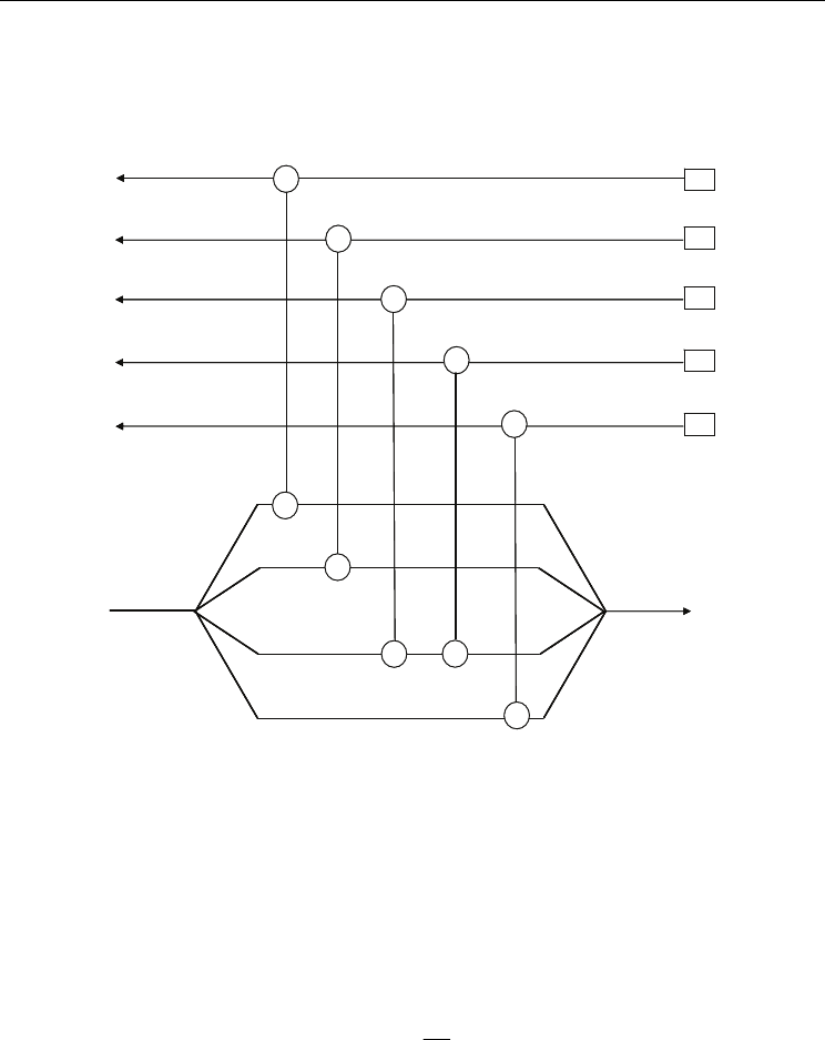
Figure 4 shows the temperature and volumetric variables involved in a cooling network. For
temperature and flow rate variations, the thermal performance of the network can be
determined by solving the model which is made up of
NV number of variables and the same
Evaporation, Condensation and Heat Transfer
196
number of equations. The number of variables in such a network is given by (Picon-Nuñez et
al., 2002):
NV = S + 2 C + M (22)
C1
C3
C4
H1
H2
H3
H4
Cooling
water
C5
H5
C2
t
1
t
2
t
3
t
4
t
5
t
6
t
7
T
1
T
2
T
3
T
4
T
5
T
6
T
7
T
8
T
9
T
10
V
1
V
2
V
3
V
4
V
T
C1
C3
C4
H1
H2
H3
H4
Cooling
water
C5
H5
C2
t
1
t
2
t
3
t
4
t
5
t
6
t
7
T
1
T
2
T
3
T
4
T
5
T
6
T
7
T
8
T
9
T
10
V
1
V
2
V
3
V
4
V
T
Fig. 4. Temperature variables in a water cooling network.
Where S is the number of streams; C is the number of coolers and M is the number of mixing
points. So, for the case shown in Figure 4 we have that NV= 6+2x5 +1=17. The solution of
the hydraulic model described in section 2 determines the values of the volumetric flow
rates in the branches, so we only need to determine the set of equations in order to solve for
the outlet temperatures of the system. These equations are: a) the stream inlet temperatures;
b) process streams outlet temperatures (Equation 18); c) cooler outlet temperatures
(Equation 19) and d) outlet temperature at mixing points. From an energy balance around
the mixing point we have that:
n
i
mi
T
i=1
V
t= t
V
⎛⎞
⎜⎟
⎜⎟
⎝⎠
∑
(23)
Where tm is the temperature of water at the mixing point, Vi is the water volumetric flow
rate of branch i and VT is the total water volumetric flow rate handled by the system. The
known variables for a given network are: inlet temperatures, water flow rates, exchanger
thermal effectiveness and Cr values.

Modelling the Thermo-Hydraulic Performance of
Cooling Networks and Its Implications on Design, Operation and Retrofit
197
4. Flexible operation of single heat exchangers
During operation, a heat exchanger is subject to variations in operating conditions that may
result in a reduction or increase of the exchanger heat duty. A single heat exchanger that
exhibits flexible operation has the following essential features: its installed surface area is
carefully oversized according to the expected increase on the process throughput and is
fitted with a bypass system (see Figure 3). The way these two features are used in operation
in order to maintain the required heat load is as follows: a) Normal operation: the bypass
operates partly opened; b) Increased throughput: in order to compensate for the required
increase in heat load removal the bypass closes thus increasing the water flow rate through
the cooler and its heat removal capacity. This mode of operation also applies in situations
where the ambient wet bulb temperature increases; c) Reduced plant throughput: the bypass
is further opened to reduce the water flow rate through the exchanger, thus reducing the
heat transfer coefficient and consequently the heat load. This mode of operation also applies
when the web bulb temperature goes down.
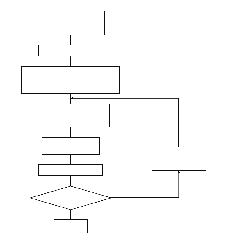
The size of the heat exchanger is determined for the expected set of conditions which require
the largest surface area. This corresponds to the case where throughput and cooling water
temperature are increased. The flow diagram of Figure 5 shows an approach for the design
of a heat exchanger given a K value. Chemical plants often need to install a new cooler in an
existing cooling network. This task should be undertaken by considering all the components
of the network. It is necessary to define some operational data to design the new heat
exchanger, for instance: allowable pressure drop, maximum heat load and a reference
volumetric flow. Heat exchangers are related to K values from their geometrical features;
therefore, it is possible to add a K resistance into an existing cooling water network for an
expected hydraulic and thermal behaviour; the aim of this approach is to determine an
approximate size of the new heat exchanger and to assess the performance of the whole
network; this is, the way water flow rate is distributed and the effect upon the existing
exchangers. Finally, after calculating these parameters, the heat transfer surface area and the
number of tubes are determined.
5. Flexible design of cooling water systems
The principles described for the case of a flexible design of a single heat exchanger can be
applied to cooling systems. Coolers are designed for the largest expected production rate, so
they will be over designed for normal operation. When the process operates under normal
production rate, the excess of water is returned back to the cold pond by means of a bypass.
As the production rate increases, the bypass closes increasing the water flow rate through
the system and thus the heat removal. For the case of lower production rate, the bypass is
further opened and more water is recycled back to the cold water pond. When the water
flow rate returned back to the cold pond equals the flow capacity of a single pump, one of
the pumps can be taken out of service. On the other hand, as the cooling duty increases, the
pump is set back into operation. An alternative means of controlling the water flow rate is
the use of a pump velocity control system. This approach has the benefit of avoiding large
power demands with the shut down and starts of the pumps. Further analysis is needed for
best choosing the right control system.
Evaporation, Condensation and Heat Transfer
198
From heat balance
determine V; estimate a
value for K
Determine ΔP
Fix exchanger geometry:
length, shell diameter,tube diameter,
tube pitch, tube arrangement.
Determine No. tubes
Calculate ΔP
calc
ΔPcalc - ΔP ≤ error
Yes
Final design
New shell diameter
and No. of tubes
Calculate overall heat transfer
Coefficients and ΔTlm
Fig. 5. Algorithm for the design of a heat exchanger in existing cooling network.
The design approach for flexible cooling systems involves thermal and hydraulic aspects,
this is, it considers: pipe length, height, fittings, valves, cooling tower, pump capacity and
heat exchanger performance. The approach starts by specifying the process and water
temperatures, flow rates and physical properties; the values of K for each exchanger related
to their specified pressure drop. For a flexible design the maximum expected production
rate is considered. Then lengths and diameters for the various flow system components are
determined and so their K value. For each branch, the summation of the K values is
determined and then the value for the whole system is obtained by adding the K values of
the various branches. Given the total water flow rate for the system, the total pressure drop
is calculated. Figure 6 shows a flow chart for the thermo-hydraulic design of water cooling
networks.