AckermannTh. (ed) Wind Power in Power Systems
Подождите немного. Документ загружается.


//INTEGRAS/KCG/P AGIN ATION/ WILEY /WPS /FINALS_1 4-12- 04/0470855088_ 30_CHA29 .3D – 661 – [653–676/24]
17.12.2004 10:52PM
I have used the model of the SVC unit that was developed and implemented as a user-
written model in the simulation tool PSS/E
TM
at the Danish co mpany NESA in
cooperation with the manufacturer ABB Power Systems (Noroozian, Knudsen and
Bruntt, 1999). NESA kindly permitted use of the SVC model.
29.3.1 Wind turbine parameters
The demand for dynamic reactive compensation is dependent on the parameters of
fixed-speed wind turbines, which are both the induction generator parameters and the
mechanical system parameters. In Akhmatov et al. (2003) my colleagues and I showe d
that demands for dynamic reactive compensation can be significantly reduced if:
.
stator resistance, stator reactance, magnetising reactance and rotor reactance are reduced;
.
rotor resistance is increased (however, this will also increase power losses in the rotor
circuit during normal operation);
.
mechanical construction is reinforced in terms of increasing turbine rotor inertia and
increasing shaft stiffness.
By reducing the demand for dynamic reactive compensation one improves short-term
voltage s tability and the ride-through capability. Table 29.2 illustrates the effect of reinfor-
cing the wind turbine’s mechanical construction in order to reduce the demand for dynamic
reactive compensation. The generator and shaft system data show that the only reasonable
comparison is that for different Type A wind turbines. Therefore, an analysis of short-term
voltage stability could be started by comparing such data for Type A wind turbines
produced by different manufacturers. The controllability of Type A wind turbines also
has to be taken into account.
29.3.2 Stabilisation through power ramp
According to Danish specifications (Eltra, 2000), large wind farms have to be able to
reduce their power supply on request. The power may have to be reduced from any
Table 29.2 Mechanical construction in relation to the static VAR compensation (SVC) unit
capacity needed for voltage reestablishment.
Mechanical construction parameter Capacity of SVC unit (MVAR)
Turbine rotor inertia (s) Shaft stiffness (p.u./el.rad)
2.5 0.30 100
a
2.5 0.15 125
2.5 0.60 50
4.5 0.30 50
a
Default case.
Source: Akhmatov et al., 2003a. From Electrical Power and Energy Systems, volume 25, issue 1,
V. Akhmatov, H. Knudsen, A. H. Nielsen, J. K. Pederson and N. K. Poulsen, ‘Modelling and
Transient Stability of Large Wind Farms’, pp. 123–144, copyright 2003, with permission from Elsevier.
Wind Power in Power Systems 661

//INTEGRAS/KCG/P AGIN ATION/ WILEY /WPS /FINALS_1 4-12- 04/0470855088_ 30_CHA29 .3D – 662 – [653–676/24]
17.12.2004 10:52PM
operational point to an operational point of less than 20 % of rated power in less than
2 s. This procedure is called power ramping. It has been demonstrated that a power
ramp can stabilise large wind farms at a short-circuit fault (Akhmatov, 2001). The
power ramp can effectively be achieved by using the active-stall control of fixed-speed
wind turbines (Akhmatov et al., 2001). In the case of Type A wind turbines, excessive
overspeeding of the wind turbines initiates voltage instability (Akhmatov, 2001). Power
ramp operation means that the wind turbines are decelerated during a grid fault, and in
this way excessive overspeeding is prevented. An external system gives an external signal
that requests a power ramp. The signal is given when abnormal operation at the
connection point of the wind farm is registered, such as a sudd en voltage drop.
There is a delay between the moment the grid fault occurs and the moment the
external signal is given to the wind farm. This delay is about 200–300 ms (Akhmatov
et al., 2003). This means that the request comes only after the grid fault is cleared.
Before the power ramp is requested, the wind turbines are controlled by the regular
control systems of active stall (i.e. by the power optimisation algorithm). If the external
signal requests the power ramp, the regular control systems are switched off and replaced
by the control strategy of the power ramp. This means that the reference blade angle of
each wind turbine in the farm is set to the predefined value corresponding to an output
power of 20 % of rated power (Akhmatov et al., 2003). The reference blade angle during
the power ramp is computed based on the incoming wind and the rotational speed of the
wind turbine rotor. Using the blade servo, the reference value of the blade angle will be
reached. However, there are restrictions on the pitching rate (see Section 27.3.3).
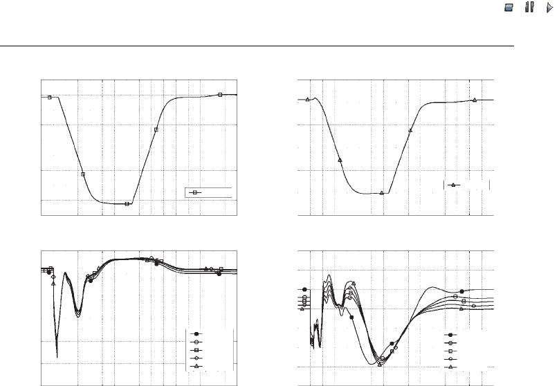
Figure 29.4 shows the computed behaviour of a modern 2 MW wind turbine using the
power ramp during a grid fault. The curves correspond to selected wind turbines in large
wind farms. It can be seen that the mechanical power can be reduced from rated
operation to 20 % of rated operation in less than 2 s. Operation with reduced power
output lasts only a few seconds. This is necessary to prevent fatal overspeeding and it
contributes to volta ge reestablishment after a grid fault and to the fault ride through
capability of the wind farm. In this particular case, the voltage in the power system is
reestablished without use of dynamic reactive compensation (i.e. it is reestablished only
through the power ramp achieve d by active-stall control) and the wind turbines ride
through the fault.
When the power ramp mode is cancelled, the regular control system of active stall is
restarted and becomes operational. The power output will be optimised according to the
incoming wind and the rotational speed of the turbi ne rotor.
If the grid fault is cleared by tripping a number of transmission lines, the short-circuit
capacity of the transmission network is changed. The voltage does not reestablish itself
to the same level as before the grid fault. The rotational speed will also be slightly
different from the value dur ing prefault operation. The result is that the operational
conditions of the wind turbine rotors differ slightly from the those during prefault
conditions. It is argued here that the blade angles of individual wind turbines will not
necessarily be reestablished to the positions prior to the grid fault. The regular control
systems of active stall will find other optimised blade-angle posit ions to reach the
desired power outputs. The curves in Figure 29.5 illustrate this. If the power ramp is
used to stabilise a large wind farm, this will not trigger interaction between the wind
turbines. The simulation results show that the wind turbines will show a coherent
662 Aggregated Modelling and Short-term Voltage Stability
//INTEGRAS/KCG/P AGIN ATION/ WILEY /WPS /FINALS_1 4-12- 04/0470855088_ 30_CHA29 .3D – 663 – [653–676/24]
17.12.2004 10:52PM
response during the grid disturbance. Once the operation of the wind farm is reestab-
lished, there are no further fluctuations of voltage or elect ric power.
In general, use of blade-angle control to stabili se large wind farms equipped with
Type A wind turbines is a useful tool for maintaining transient voltage stability
(Akhmatov et al., 2003). The Danish offshore wind farm at Rødsand applies a similar
technical solution. The rated power of the Rødsand offshore wind farm is 165 MW, and
the farm was taken into operation in 2003. The Rødsand offshore wind farm comprises
72 Type A2 wind turbines from the manufacturer Bonus Energy.
29.4 Wind Turbines with Variable Rotor Resistance
The feature of variable rotor resistance (VRR) is designed as follows: the converter is
connected to the rotor circuit of an induction generator through the slip rings. The
operation of the converter means that an external resistance is added to the impedance
of the rotor circuit. For an analysis of voltage stability, this is reflected in a simplified
representation of the converter control as a dynamically controlled external rotor
–2
–3
–4
–5
–6
–7
–8
–9
–10
–11
0.0 0.5 2.5 3.5
Time (s)
WT 10
WT 10
WT 10
WT 50
WT 60
WT 70
WT 80
WT 10
WT 50
WT 60
WT 70
WT 80
(a)
(c)
(d)
(b)
1.0 1.5 2.0 3.0 4.0 4.5 5.0 5.5 6.0 6.5 7.0 7.5 8.0
0.0 0.5 2.5 3.5
Time (s)
1.0 1.5 2.0 3.0 4.0 4.5 5.0 5.5 6.0 6.5 7.0 7.5 8.0
0.0 0.5 2.5 3.5
Time (s)
1.0 1.5 2.0 3.0 4.0 4.5 5.0 5.5 6.0 6.5 7.0 7.5 8.0
0.0 0.5 2.5 3.5
Time (s)
1.0 1.5 2.0 3.0 4.0 4.5 5.0 5.5 6.0 6.5 7.0 7.5 8.0
1.2
1.0
0.8
0.6
0.4
0.2
0.0
3.0
2.5
2.0
1.5
1.0
0.0
–0.5
2.4
2.0
1.6
1.2
0.8
0.4
0.0
Mechanical power (MW)
Electrical power (MW)
Voltage (p.u.)
Blade angle (degrees)
0.5
Figure 29.4 Response of a large wind farm to a short-circuit fault, with use of a power ramp:
(a) blade angle of a selected wind turbine, (b) mechanical power of a selected wind turbine, (c)
voltage and (d) electric power of selected wind turbines. Voltage is reestablished without using
dynamic reactive compensation. Note: for the layout of wind turbines WT 01–WT 80, see Figure
29.1 Reprinted from Electrical Power and Energy Systems, volume 25, issue 1, V. Akhmatov,
H. Knudsen, A. H. Nielsen, J. K. Pederson and N. K. Poulsen, ‘Modelling and Transient Stability
of Large Wind Farms’, pp. 123–144, copyright 2003, with permission from Elsevier
Wind Power in Power Systems 663
//INTEGRAS/KCG/P AGIN ATION/ WILEY /WPS /FINALS_1 4-12- 04/0470855088_ 30_CHA29 .3D – 664 – [653–676/24]
17.12.2004 10:52PM
Generator (PMG)/
Rotor (DFIG) converter
Generator (PMG)/
Rotor (DFIG) converter
Grid-side converter
Grid-side
converter
IGBT switch
Smoothing inductorSmoothing inductor
Smoothing inductor
To power network
To power network
DC link
DC link
To generator
To generator
E
1
= E
1α
+jE
1β
= |E
1
|∠ϕ
1
U
2
= U
2α
I
2
= I
2α
+jI
2β
E
2
= E
2α
+jE
2β
E
1
PI PI
PI PI
PI
PI PI
Q
2
C
J
1
U
DC
U
2
P
2
R
2
jX
2
Q
2
E
2
J
2
I
1
I
2
I
1
= I
1α
+jI
1β
ω
G
ω
G, Ref
P
G, Ref
Q
G, Ref
U
2α, Ref
Q
2, Ref
U
2α
Q
G
P
G
I
1α, Ref
I
1β, Ref
I
2β, Ref
I
1β
E
1β
E
1α
I
1α
(a)
(b)
(c)
(e)
PI PI
PI
ω
G
ω
G, Ref
P
G, Ref
Q
G, Ref
Q
G
P
G
ϕ
1
|E
1
|
(f)
PI
PI
PI
X
2
–X
2
I
2α, Ref
I
2β, Ref
I
2β
I
2α
E
2
α
U
2α
E
2
β
U
DC, Ref
U
DC
(d)
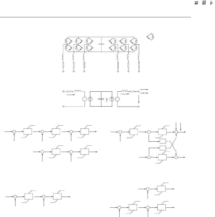
Figure 29.5 Frequency converter and its control system in voltage stability investigations: (a) the
main components and integrated gate bipolar transistor (IGBT) switches, (b) generic electric
scheme, (c) generic control of rotor converter of the doubly fed induction generator (DFIG),
(d) generic control of the grid-side converter, (e) supplementary control of reactive power from the
grid-side converter, and (f) generic control of the generator converter of the permanent magnet
generator (PMG). Note:PI¼proportional–integral controller; c ¼...; E
1
¼voltage source of DFIG
rotor converter on PMG converter; |E
1
| ¼magnitude of E
1
; E
1
¼ active component of E
1
;
E
1
¼ reactive component of E
1
; E
2
¼voltage source of grid-side converter;
E
2
¼ active component of E
2
; E
2
¼ reactive component of E
2
; I
1
¼rotor current of DFIG or
generator current of PMG; I
1
¼ active component of I
1
; I
1
¼ reactive component of I
1
;
I
1,Ref
¼ desired value of I
1
; I
1,Ref
¼ desired value of I
1
; I
2
¼current of grid-side converter;
I
2
¼ active component of I
2
; I
2
¼ reactive component of I
2
; I
2,Ref
¼ desired value of I
2
;
I
2,Ref
¼ desired value of I
2
; J
1
¼charging DC current; J
2
¼discharging DC current;
664 Aggregated Modelling and Short-term Voltage Stability

//INTEGRAS/KCG/P AGIN ATION/ WILEY /WPS /FINALS_1 4-12- 04/0470855088_ 30_CHA29 .3D – 665 – [653–676/24]
17.12.2004 10:52PM
resistance, VRR. In Akhmatov et al. (2003) my colleagues and I describe the model of
Type B wind turbines with a generic control system of VRR with a proportional integral
(PI) controller. The rotor current magnitude controls the value of the external resis-
tance.
The VRR feature is commonly applied in combinat ion with pitch control in order to
reduce flicker (i.e. to improve power quality). In Akhmatov et al. (2003) we demon-
strated that this feature can also be used to improve short-term voltage stability. We also
included the results of an analysis of short-term voltage stability carried out with a wind
farm model with 80 Type B wind turbines. Grid fault s did not trigger any mutual
oscillations between the Type B wind turbines, and the electric and mechanical par-
ameters of the wind turbines show a coherent response.
Use of VRR means that the demand for dynamic reactive compensation in order to
reestablish voltage can be reduced significantly. Furthermore, if pitch control is applied
to prevent excessive overspeeding of wind turbines during grid faults, this will also
contribute to improved short-term voltage stability and the fault-ride-through capability.
VRR (i.e. the converters) cannot be used to control reactive power or cover the static
reactive demands of the induction generators because the converter is applied together
with induction generators that absorb reactive power from the power grid; it is not
designed to control the excitation of such generators. During transient events in the
electric power networks converter protection also has to be taken into account. The
converters may, for example, block during excessive machine current transients
(Akhmatov, 2003a).
Note: the results presented in this section have been discussed with the Danish
manufacturer Vestas Wind Systems, which produces the Opti-Slip
TM
wind turbines.
29.5 Variable-speed Wind Turbines with Doubly-fed Induction Generators
I now wish to present the simulation results for 80 variable-speed wind turbines
equipped with DFIGs. Partial-load frequency converters use the integrated gate bipolar
transistor (IGBT) switches to control the DFIGs. Figure 29.5 shows schematically the
Figure 29.5 (continued) P
2
¼electric power of grid-side converter; P
G
¼generator electric
power; P
G, Ref
¼desired value of P
G
; Q
2
¼reactive power of grid-side converter; Q
2, Ref
¼desired
esired value of Q
2
; Q
G
¼generator reactive power; Q
G, Ref
¼desired value of Q
G
; R
2
¼resistance
of smoothing inductor; U
2
¼terminal voltage; U
2
¼magnitude of terminal voltage;
U
2,Ref
¼ desired value of U
2
; U
DC
¼DC link voltage; U
DC,Ref
¼desired value of U
DC
;
X
2
¼reactance of smoothing inductor; ’
1
¼ phase angle; !
G
¼ generator rotor speed;
!
G, Ref
¼ desired value of !
G
; Parts (c)–(e) reprinted from Wind Engineering, volume 27, issue 2,
V. Akhmatov, ‘Variable-speed Wind Turbines with Doubly-fed Induction Generators, Part III:
Model with the Back-to-back Converters’, pp. 79–91, copyright 2003, with permission from
Multi-Science Publishing Co. Ltd, Part (f) reprinted from Wind Engineering, volume 27, issue 6,
V. Akhmatov, A. H. Nielsen, J. K. Pedersen and O. Nymann, ‘Variable-speed Wind Turbines with
Multi-preSynchronous Permanent Magnet Generators and Frequency Converters, Part I:
‘Modelling in Dynamic Simulation Tools’, pp 531–548, copyright 2003, with permission from
multi-science Publishing Co. Ltd
Wind Power in Power Systems 665

//INTEGRAS/KCG/P AGIN ATION/ WILEY /WPS /FINALS_1 4-12- 04/0470855088_ 30_CHA29 .3D – 666 – [653–676/24]
17.12.2004 10:52PM
converter and its control. In Akhmatov (2002) I provide the modelling details regarding
the DFIG, shaft system, turbine rotor and generic pitch-control system. In Akhmatov
(2003b) I explain the generic model of the partial-load frequency converter and its
control systems applied in the analysis of voltage stability. It is, however, necessary to
present briefly the converter model in order to understand better the results presented in
this section.
The accuracy of the simulation results depends on a variety of factors. One is the
representation of the partial-load frequency converter and its control. Several studies on
the analysis of voltage stability (Pena et al., 2000; Røstøen, Undeland and Gjengedal,
2002) assume that the rotor converter representation is sufficient for such an analysis
and therefore they neglect the grid-side converter. The reason is that the grid-side
converter has a small power capacity, and it is assumed that this converter can always
follow its references, such as DC link voltage and reactive current.
Unless the terminal voltage changes significantly, this assumption is correct. How-
ever, if there is a significant voltage drop during a short-circuit fault, the grid-side
converter is not able to follow its references (Akhmatov, 2003b). If one neglects the
converter one introduces inaccuracy with respect to the converter’s response during grid
disturbances.
First, this inaccuracy shows when the predictions of transients of the machine current
are excessively high (Akhmatov, 2003b). This is unacceptable, because, basically, the
rotor converter blocks in order to protect against overcurrents (Akhmatov, 2002). This
means that the oversimplified converter model may predict a too frequent blocking of
the converters.
Second, the transient behaviour of the DC link voltage is not available if the grid-side
converter is neglected. When the grid voltage drops, the grid-side converter cannot
supply elect ric power and the DC link voltage starts to fluctuate (Akhmatov, 2003b).
The converter’s protective system monitors the DC link voltage and orders the converter
to block if the DC voltage exceeds a given range.
Third, the damping characteristics of the torsional oscillations excited in the shaft
system may be predicted incorrectly when one applies the oversimplified converter
representation (Akhmatov, 2003a). This may result in misleading conclusions with
respect to the intensity of shaft oscillations and the predicted load on the shaft gear.
It is also important to mention that the grid-side converter can be set to control reactive
power. Through its restricted power capacity, this reactive power control may have an
effect on the voltage recovery rate and may contribute to the successive converter restart,
if the rotor converter has been blocked during the grid fault (Akhmatov, 2003a). This
important behaviour is omitted if the grid-side converter is neglected in the model.
Details regarding the complexity of the converter models in the case of DFIGs and their
partial-load converters were discussed with the manufacturer Vestas Wind Systems, which
produces the Opti-Speed
TM
wind turbines. Vestas Wind Systems agreed that an analysis
of short-term voltage stability should also include a converter model with representations
of the grid-side converter and the DC link rather than only of the rotor converter. It is
necessary to predict with sufficient accuracy the electric parameters that have an effect on
the converter blocking (and restart) during transient events in the power grid.
Vestas Wind Systems kindly provided support regarding the tuning of the parameters
of the generic model of a partial-load frequency converter and its control system.
666 Aggregated Modelling and Short-term Voltage Stability

//INTEGRAS/KCG/P AGIN ATION/ WILEY /WPS /FINALS_1 4-12- 04/0470855088_ 30_CHA29 .3D – 667 – [653–676/24]
17.12.2004 10:52PM
Consequently, the con verters of all the wind turbines in the farm are modelled with
representation of the rotor converters as well as the grid-side converters and their
respective control systems, in order to reach a higher accuracy. Figures 29.5(c) and
29.5(d) give the generic control systems of the rotor and the grid-side converters of the
DFIG. The rotor converter controls the generator in a synchronously rotating
(, )-reference frame with the -axis oriented along the terminal voltage vector. Using
this control, the electric and reactive power of the DFIG are controlled independent of
each other (Yamamoto and Motoyoshi, 1991).
The grid-side converter control is similar to that of a Statcom (Akhmatov, 2003a;
Schauder and Mehta, 1999). The grid-side converter is controlled in the same reference
frame as the rotor converter (Akhmatov, 2003b). The grid-side converter control is designed
with independent control of the DC link voltage and the reactive current. Voltage compen-
sation is achieved by cross-coupling. The switching dynamics in both converters is
neglected, since the rotor converter and the grid-side converter are able to follow their
respective reference values for the induced voltage sources at any time (Akhmatov, 2003b).
Figure 29.6(e) shows the supplementary system to control reactive power from the
grid-side converter. Here, control coordination between the rotor and the grid-side
converters is necessa ry (Akhmatov, 2003b).
29.5.1 Blocking and restart of converter
The wind turbines have to operate without interruption during grid faults that is the
fault-ride-through. During such an event, the voltage drops. This causes transients in the
machine and the grid-side converter currents. There are also fluctuations in the DC link
voltage (Akhmatov, 2003b). The converter’s protective system monitors currents in the
rotor circuit and the grid-side converter, the DC link voltage, the terminal voltage, the
grid frequency and so on. The converter will block if one or more monitored values
exceed their respective relay settings. The characteristic blocking time is in the range of a
few milliseconds (Akhmatov, 2002). The rotor converter stops switching and trips. The
converter blocking may lead to disconnection of the wind turbine (Akhmatov, 2002).
In Akhmatov (2002) I suggest a feature to maint ain the ride-through capability with a
fast restart of the converter after the fault. This feature was then validated by simula-
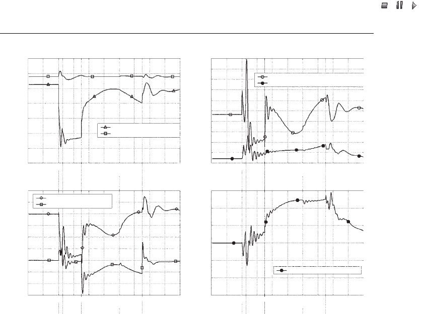
tions (Akhmatov, 2003a). The simulated curves shown in Figure 29.6 illustrate the fault-
ride-through capability with a fast restart of the converter. The curves correspond to
wind turbine WTG 01. From the start of the simulation to tim e t ¼T
1
, the power system
is in normal operation. At time T
1
, the transmission power network is subjected to a
short-circuit fault.
At time t ¼T
2
, the rotor converter blocks by overcurrent (transients) in the rotor
circuit. The rotor circuit is short-circuited through an external resistor (Akhmatov,
2002). When the rotor converter blocks, the wind turbine operates as a Type A1 wind
turbine with an increased rotor resistance. Pitch control protects against excessive
overspeeding of the wind turbine, as explained in Se ction 29.3.2. The grid-side converter
operates as a Statcom, controlling DC link voltage and reactive power. This contributes
to a faster reestablishment of the terminal voltage. This controllability is, however,
restricted by the power capacity of the grid-side converter.
Wind Power in Power Systems 667
//INTEGRAS/KCG/P AGIN ATION/ WILEY /WPS /FINALS_1 4-12- 04/0470855088_ 30_CHA29 .3D – 668 – [653–676/24]
17.12.2004 10:52PM
The grid fault is cleared at time t ¼T
3
. Once the voltage and grid frequency are
reestablished within their respective ranges, the rotor converter synchronisation is
started. The IGBT of the rotor converter starts switching and the external resistance is
disrupted from the rotor circuit. During synchronisation, the rotor co nverter prepares
to restart. Synchronisation begins at time t ¼T
4
and protects the rotor converter against
blocking during the restart sequence, which could be caused by excessive transients in
the rotor current or unacceptably large fluctuations of the DC link voltage.
At time t ¼T
5
, the rotor converter has restarted. Shortly after, normal operation of
the wind turbine is reestablished. The feature with a fast restart of the rotor converter is
designed for a ride-through operation of wind turbines in a large wind farm during grid
disturbances.
29.5.2 Response of a large wind farm
One of the main concerns regarding wind farms is the risk of mutual interaction between
the converter control systems of a large number of Type C wind turbines. Such concerns
1.4
1.2
1.0
0.8
0.6
0.4
0.2
0.0
1.4
1.6
1.8
2.0
1.2
1.0
0.8
0.6
0.4
0.2
0.0
0.6
0.4
0.2
0.0
–0.2
–0.4
–0.6
2.0
2.5
3.0
1.5
1.0
0.5
0.0
–0.5
–1.0
–1.5
0.3
(a) (b)
(d)(c)
0.4 0.5 0.6 0.7 0.8 0.9 1.0 1.1 1.2 1.3
Voltage (p.u.)
Current (p.u.)
Time (s)
0.3 0.4 0.5 0.6 0.7 0.8 0.9 1.0 1.1 1.2 1.3
Time (s)
0.3 0.4 0.5 0.6 0.7 0.8 0.9 1.0 1.1 1.2 1.3
Time (s)
0.3 0.4 0.5 0.6 0.7 0.8 0.9 1.0 1.1 1.2 1.3
Time (s)
WT 01: Terminal voltage
WT 01: Rotor current
WT 01: Gride-side converter current
WT 01: Gride-side converter
WT 01: DC link voltage
WT 01: Electric power
Electric power (MW), Reactive power (MVAR)
WT 01: Reactive power
Reactive power (MVAR)
T
1
T
2
T
3
T
4
T
5
T
1
T
2
T
3
T
4
T
5
Figure 29.6 Uninterrupted operation feature with fast restart of the rotor converter: (a) terminal and
DC link voltages, (b) rotor and grid-side converter current, (c) electric and reactive power, and (d)
reactive power of grid-side converter. Reprinted from Akhmatov, V., Analysis of Dynamic Behaviour
of Electric Power Systems with Large Amount of Wind Power, Ph.D dissertation, Technical University
of Denmark, Kgs. Lyngby, Denmark, copyright 2003, with permission from the copyright holder
668 Aggregated Modelling and Short-term Voltage Stability
//INTEGRAS/KCG/P AGIN ATION/ WILEY /WPS /FINALS_1 4-12- 04/0470855088_ 30_CHA29 .3D – 669 – [653–676/24]
17.12.2004 10:52PM
are reinforced during the following situations: (a) fast-acting partial-load frequency
converters of the DFIG and (b) when the rotor converters of many wind turbines
execute blocking and restarting sequences during a short time interval at a grid
fault. Voltage stability is maintained without dynamic reactive compensation. The
grid-side converters of the DFIG will control reactive power and voltage during the
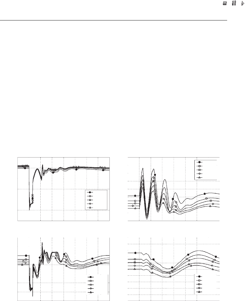
transient event (Akhmatov, 2003a). Figure 29.7 includes the simulated curves for
the selected wind turbines operating at different operational points. The simulation
results do not indicate any risk of mutual interaction between the converters of the
different wind turbines. The Type C wind turbines show a coherent response during
the grid fault.
Properly tuned converters are not expected to cause mutual interaction between
wind turbines in large wind farms (Akhmatov, 2003a). This result is, however, based
on the given control strategy of the variable-speed wind turbines and the given power
network.
1.2 0.2
0.18
0.16
0.14
0.12
0.1
0.08
0.06
0.04
1.0
0.8
0.6
0.4
0.2
0.0
0.0 0.5 1.0 1.5 2.0 2.5 3.0 3.5 4.0
Time (s)
0.0 0.5 1.0 1.5 2.0 2.5 3.0 3.5 4.0
Time (s)
Time (s)
Time (s)
Voltage (p.u.)
Speed deviation (p.u.)
WT 10
WT 50
WT 60
WT 70
WT 80
WT 10
WT 50
WT 60
WT 70
WT 80
WT 10
WT 50
WT 60
WT 70
WT 80
WT 10
WT 50
WT 60
WT 70
WT 80
3.0
2.5
2.0
1.5
1.0
0.5
0.0
–0.5
0.0 0.5 1.0 1.5 2.0 2.5 3.0 3.5 4.0
0.0 0.5 1.0 1.5 2.0 2.5 3.0 3.5 4.0
2.5
2.3
2.1
1.9
1.7
1.5
1.3
1.1
0.9
0.7
0.5
Electric power (MW)
Mechanical power (MW)
(a)
(c)
(b)
(d)
Figure 29.7 Response of a large wind farm with doubly fed induction generators (DFIGs) to a
short-circuit fault using: (a) terminal voltage, (b) generator rotor speed, (c) electric power, and
(d) mechanical power (illustration of pitching) of selected wind turbines; voltage is reestablished
without dynamic reactive compensation. Note: For the layout of wind turbines WT 01–WT 80, see
Figure 29.1. Reprinted from Akhmatov, V., Analysis of Dynamic Behaviour of Electric Power
Systems with Large Amount of Wind Power, Ph.D dissertation, Technical University of Den-
mark, Kgs. Lyngby, Denmark, copyright 2003, with permission from the copyright holder
Wind Power in Power Systems 669

//INTEGRAS/KCG/P AGIN ATION/ WILEY /WPS /FINALS_1 4-12- 04/0470855088_ 30_CHA29 .3D – 670 – [653–676/24]
17.12.2004 10:52PM
29.6 Variable-speed Wind Turbines with Permanent Magnet Generators
In this Section I present the simulation results based on 80 variable-speed wind turbines
equipped with PMG and frequency converters. Table 29.3 shows the data for the wind
turbine. This wind turbine type has no gearbox and therefore the generat or is direct-
driven by the wind turbine through the low-speed shaft (Grauers, 1996). The generator
has a large number of poles and a relatively large value of reactance (Spooner, Williamson
and Catto, 1996).
The generator consists of two sections of slightly above 1 MW placed on one rotor
shaft. Figures 29.5(d)–29.5(f) illustrate the generi c control system of the frequency
converter. The generic control system of the grid-side converter is similar to the control
system applied in the case of a DFIG. The PMG is controlled by the generator
converter, where the electric power is controlled by the phase angle, and its reactive
power (kept reactive-neutral) is controlled by the voltage magnitude.
Again, the main concern is to achieve a ride-through operation of the Type D wind
turbines with PMGs. The protective system of the frequency converter monitors the
machine current, the current in the grid-side converter, the DC link voltage, the terminal
voltage, the grid frequency and so on; the converter will block if one or more of the
monitored parameters exceed their relay settings. This may lead to disconnection and
stopping of the wind turbine. In the case of a PMG, the machine current magnitude is
also among the critical parameters be cause an excessive machine current may demag-
netise the permanent magnets.
These concerns have to be taken into account when presenting a ride-through feature
with blocking and fast restart of the converter during a grid fault. Figure 29.8 shows the
dynamic behaviour of Type D wind turbines with PMGs. The short- circuit fault occurs
at time t ¼T
1
. At time t ¼T
2
, the converter’s protective system registers an abnormal
operation and requests a blocking of the generator converter. The IGBT switches stop
switching and open. Then the DC link capacitor will be charged through the diode
Table 29.3 Data for a 2 MW wind turbine equipped with a permanent magnet generator (PMG)
Generator Value Grid-side converter Value
Rated power (MW) 1.01 2 Rated power (MW) 2
No-load voltage (p.u.) 1.40
a
Rated voltage (p.u.) 1.0
b
Rotational speed (rpm) 10.5–24.5 Rated frequency (Hz) 50
Number of poles 64 Rated DC link voltage 1.16
c
Lumped inertia (s) 4.8 DC link capacitor (p.u.) 0.1
Resistance (p.u.) 0.042 Mains resistance (p.u.) 0.014
Reactance X
D
(p.u.)/X
Q
(p.u.) 1.05/0.75 Mains reactance (p.u.) 0.175
a
966 V.
b
690 V.
c
800 V.
Source: Akhmatov et al ., 2003. From Wind Engineering, volume 27, issue 6, V. Akhmatov,
A. H. Nielsen, J. K. Pedersen and O. Nymann, ‘Variable-speed wind turbines with multi-pole
synchronous permanent magnet generators. Part 1: Modelling in dynamic simulation tools’,
pp. 531–548, copyright 2003, with permission from Multi-Science Publishing Co.
670 Aggregated Modelling and Short-term Voltage Stability