9-й Международный симпозиум по электромагнитной совместимости и электромагнитной экологии
Подождите немного. Документ загружается.

521
MAGNETIC FIELD DISTORTION WHILE UNDERGROUND
DETONATION OF SMALL POWER CHEMICAL BLASTING CHARGE
M.
M.
F
ILATOV
,
R
USSIA
,
V.
I.
B
UTIN
,
R
USSIA
,
O.
A.
K
SENOFONTOVA
,
R
USSIA
,
V.
F.
M
OLOCHKOV
,
R
USSIA
,
O.
A.
G
ERASIMCHUK
,
R
USSIA
FSUE “VNIIA”, e-mail: vniia@vniia.ru
When performing work under the ISTC Project No.
835 Investigation of Electromagnetic Signals
Accompanying Underground Chemical Blasts there were
carried out model underground blasts of chemical
explosive charges in order to study characteristics of
electromagnetic distortion generated by detonation of
explosives. This paper represents routine of experiments,
typical experimental results and qualitative model for
interpreting magnetic field disturbance.
Induction type sensors were used for measuring of
the magnetic field disturbance. Signals from the sensors
were recorded using SONY two-channel analog audio
recorders MZ-R50. Explosive charge detonation was
initiated using igniting fuse. After the experiments the
recorded analog data was converted into digital form
using TDS-540D oscilloscope.
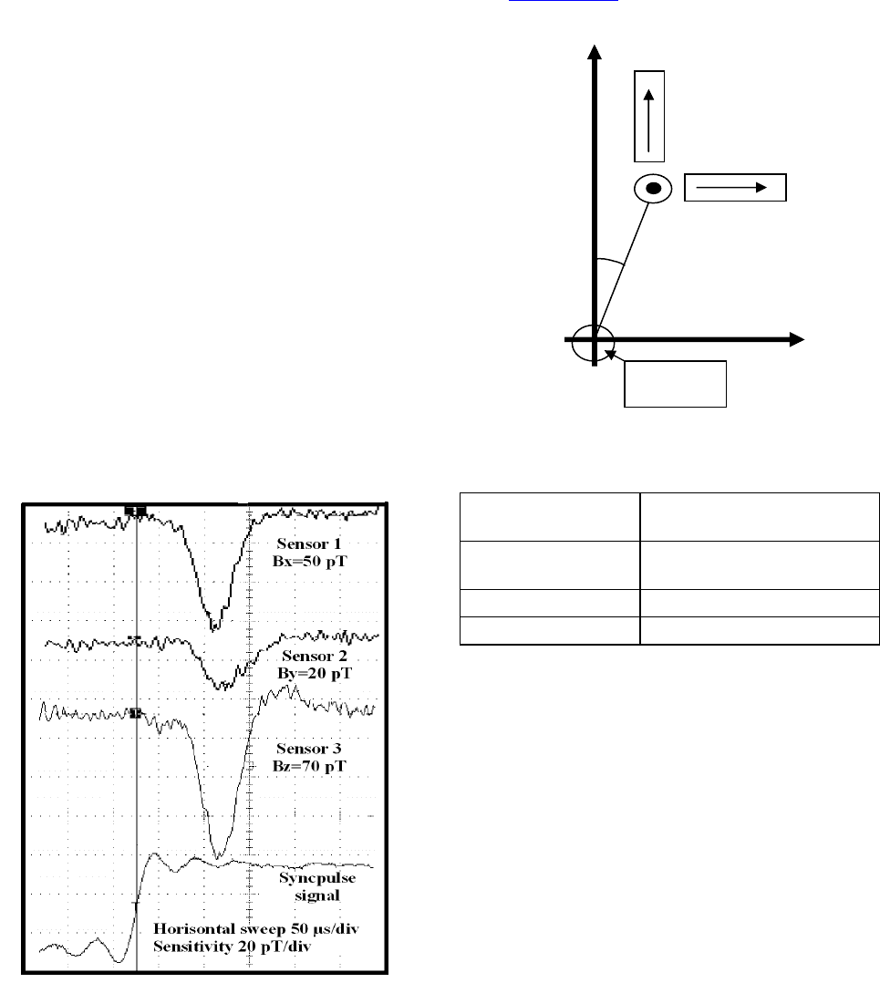
Fig. 1 shows typical transient processes obtained for
one of the underground explosions; Table 1 includes the
parameters of the blast; orientation of the sensors relative
to the blast epicenter is given in Fig. 2.
Fig. 1. Magnetic field/
Fig. 2. Orientation of the sensors relative to the blast
epicenter.
Table 1. Parameters of the blast
Date, No. and type of
blast
02.07.99, No. 21, camouflet at
2.3 m depth
Charge Cylinder of TH 50/50,
D 60 х 420 mm
2
,
weight 2.0 kg
Charge orientation Horizontal (East - West)
Detonation direction East - West
The well-known seismoelectrical and magnetic
induction effects are taken as a basis of the qualitative
model interpreting experimental results obtained. While
developing the model the following assumptions and
hypotheses were taken: explosive charge detonation
causes radial movement of ambient soil under the action
of propagating shock wave increasing its conductivity
due to the appearance of seismoelectrical effect; in the
process of conducting region expansion the current
caused by magnetic induction effect is induced inside it.
This current causes short-term disturbance of the
magnetic field. The direction and value of the induced
current are determined by the conducting region
expansion velocity, its conductivity, as well as direction
and module of the Earth magnetic field vector.
Acknowledgments - The work fulfilment was
financially supported by the ISTC under Project No. 835.
North
West
№1
№2
№3
20
0
5
m
Blast
epicenter
East
South
522
НОВЫЕ ПРИНЦИПЫ ОБЕСПЕЧЕНИЯ МОЛНИЕЗАЩИТЫ В
СИСТЕМЕ ПРЕДОТВРАЩЕНИЯ УДАРОВ МОЛНИЙ DAS ОТ
КОМПАНИИ LEC
С.
Н.
Т
ЮРЕНКОВ
1
,
Р
ОССИЯ
,
К.
В.
Е
РМАКОВ
2
,
Р
ОССИЯ
1
ООО «АСК Контур», emc@askkontur.ru,
2
ООО «Газпромэнергодиагностика», e-mail: of-
fice@gazpromenergy.ru
Аннотация. В докладе рассматриваются принцип работы, преимущества и опыт применения системы
молниезащиты Dissipation Array System® (DAS®) от компании LEC (США).
Abstract. A principle of the work, advantages and experience of the using the lightning protection from di-
rect strikes – Dissipation Array System® (DAS®) from company LEC (USA) are considered in the paper.
Введение
Несмотря на наличие систем молниезащиты
(МЗ), аварии, вызванные молниевыми разрядами
(МР) в нефтяной отрасли, поражают ежегодно до 8%
объектов и их коммуникаций [1]. По данным МЧС
России только затраты на ликвидацию последствий
аварий на нефтяных объектах составляют от 1,5 до
10 млн. долларов США. Имеется много фактов, ко-
гда после первого удара молнии, молниеприемное
устройство не воспринимает последующие разряды.
В качестве примера можно привести анализ причин
аварии на резервуаре РВС 20000 №22 Александровской
нефтеперекачивающей станции [2]. По показаниям оче-
видцев у резервуара РВС 20000 №22 возникли подряд
два разряда молнии: первый был принят отдельно стоя-
щим в 5 м от резервуара молниеприемником, а второй
пришелся непосредственно в кровлю резервуара. После
попадания МР в кровлю воспламенились пары нефти в
свободном пространстве резервуара.
Расследованием причин аварии установлено,
что МЗ была выполнена в полном соответствии с
требованиями действующей нормативной докумен-
тацией (НД) при помощи отдельно стоящих молние-
отводов на расстоянии 5м и высотой 45 м. Резервуар,
его система молниезащиты, заземление эксплуатиро-
вались так же в соответствии с НД. Причиной удара
второго разряда молнии не в молниеприемник, а в
кровлю резервуара, комиссия управления Западно-
Сибирского округа Госгортехнадзора России назвала
«снос ветром ионизированного канала воздуха».
Это говорит о том, что существующие системы
МЗ не обеспечивают на практике достаточный уро-
вень защиты от прямых МР. Таким образом, возни-
кает реальная неизбежность поражения защищаемых
объектов и персонала.
Предотвращение прямых ударов молний
Как видно из приведенного выше примера, пря-
мые удары молнии происходят даже в защищенные
объекты, а их последствия трудно переоценить. По-
мимо прямых ударов молний возможны удары в
близлежащие заземленные конструкции и объекты.
Такие явления вызывают так называемые «вторич-
ные воздействия» молний на объекты инфраструкту-
ры нефтегазовых предприятий. Можно выделить
четыре основных [4]:
1. Блуждающие токи
2. Электромагнитные импульсы
3. Электростатические импульсы
4. Связанный заряд
Все они могут приводить к возгораниям и взры-
вам либо к выходу из строя контрольно измеритель-
ной аппаратуры и автоматики. Как следствие можно
сделать вывод, что предотвращая прямые удары в
критически важные объекты и их окружение можно
снизить необходимость защиты каждой точки потен-
циально подверженной индуцированным токам и
минимизировать прочие требования к защите от пе-
ренапряжений.
В 1971 году компания Lightning Eliminators &
Consultants, Inc. (США) разработала систему
Dissipation Array ® System (DAS®), позволяющую
полностью исключить попадание молнии в защи-
щаемую область.
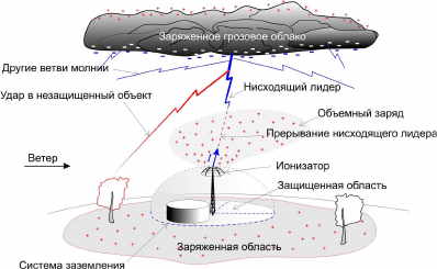
Работа системы основана на принципе точечной
разрядки, заключающейся в стекании заряда с острия
многочисленных иголок в окружающую атмосферу и
создания тем самым объемного заряда, препятствую-
щего развитию восходящих лидеров и задерживающих
движение нисходящих лидеров молнии (Рис. 1). В ре-
зультате молниевый разряд не попадает в защищаемый
объект, а разряжается в незащищенной области.
Рис. 1. Предотвращение попадания молнии с
помощью Dissipation Array ® System компании LEC.
523
DAS ® состоит из трех основных элементов:
1. Ионизатор. Это основной элемент системы
молниезащиты, содержащий тысячи иголок, перено-
сящих заряд, собранный системой заземления в ок-
ружающую атмосферу, создавая тем самым облако
объемного заряда.
При увеличении электромагнитного поля, вы-
званного надвигающимся грозовым фронтом, тради-
ционные стержневые молниеприемники формируют
восходящие стримеры, которые провоцируют удар
молнии. Многоточечный ионизатор напротив, запус-
кает процесс ионизации при несколько большей на-
пряженности поля, но при его увеличении, иониза-
ционные токи экспоненциально возрастают. По-
скольку ионы распределяются по большой площади,
никаких стримеров не возникает.
2. Система заземления. Для работы системы не-
обходимо качественное заземление. Система сбора
зарядов является источником заряда, переносимого
ионизатором в атмосферу. Как только образуется
положительный заряд, наведенный грозовым фрон-
том на поверхность земли, его часть собирается сис-
темой сбора зарядов.
Система сбора зарядов подобна обычной систе-
ме заземления, но она является приемником, а не
системой заземления для растекания токов молний.
По сути, их назначения абсолютно противоположны.
3. Система переноса заряда. Система сбора за-
рядов соединена с ионизатором с помощью низко-
омного проводника, который обеспечивает прямой
перенос заряда к ионизатору. По сравнению с тради-
ционными молниеприемниками этот проводник не-
сет существенно меньший ток и предназначен не для
переноса огромных токов молнии, а для соединения
частей системы в единое целое. Максимальный ток
не превышает нескольких миллиампер и не вызывает
никаких вторичных воздействий, имеющих место
при работе традиционных систем молниезащиты.
Предупреждение формирования восходящего
лидера от любого защищаемого объекта
Предупреждение формирования восходящих
лидеров от любого защищаемого объекта, способных
создать проводящий канал и инициировать удар
молнии в объект. Такие лидеры обычно иницииру-
ются объектами, высота которых более 200 метров,
или объектами в горной местности на такой высоте,
где суммарный подъем допускает напряжение на
наивысшей точке в пределах 10
6
вольт во время про-
цесса разряда.
Исследования, проведенные российским учены-
ми Э.М. Базеляном и его коллегами, сформулирова-
ли условия для уменьшения риска поражения объек-
та молнией. Было доказано, что использование оп-
тимизированного ионизатора способно создать и
поддерживать объемный заряд в зоне потенциально-
го риска удара молнии. Также было обнаружено, что
объемный заряд способен предотвращать зарожде-
ние групповых лидеров.
Редкие прорывы были замечены в областях, где
разряды часты и преобладают именно восходящие
молнии. В этих случаях плотность объемного заряда
должна быть существенно выше, чем нисходящий
отрицательный разряд. Пиковые молниевые токи и
сопровождающие их заряды для положительных
разрядов начинаются от земли и достигают пиковых
значений тока в 200 000 ампер. Отрицательные раз-
ряды, нисходящие от грозовой зоны, достигают пи-
ковых значений около 80 000 ампер. Поэтому в об-
ластях, где преобладают позитивные разряды, объ-
емный заряд должен быть увеличен примерно в два
раза. Электростатические поля в этих случаях значи-
тельно выше, что позволяет увеличить ионизацию.
Предупреждение касания объекта нисходя-
щими лидерами
Предупреждение касания объекта нисходящими
лидерами – значительно более сложная задача. По-
следние 100 метров до объекта молниевый лидер
движется со скоростью около 400 метров в секунду.
При таких скоростях необходимое количество объ-
емного заряда должно быть готово прежде, чем бу-
дет сформирован встречный лидер, за 50-100 милли-
секунд до прибытия нисходящего лидера.
Исследования компании LEC и полевые испы-
тания доказали, что корректно спроектированный
ионизатор DAS способен реагировать и предупреж-
дать касание молнии, генерируя комбинацию пред-
разрядного объемного заряда и реактивного объем-
ного заряда высокой плотности при приближении
молниевого лидера.
Предразрядный объемный заряд определяется
размером ионизатора, электростатическим полем,
временем между разрядами и скоростью перемеще-
ния объемного заряда. Комбинация электростатиче-
ского поля восходящих потоков, создаваемых грозой
и силами согласно закону Кулона, вызывают непре-
рывный поток ионов и постоянное перемещение за-
ряда между ионизатором и грозовой областью, как
описывал физик атмосферы Д-р Альтон Чалмерс [5].
Объемный заряд препятствует образованию группо-
вых лидеров при высокой плотности заряда.
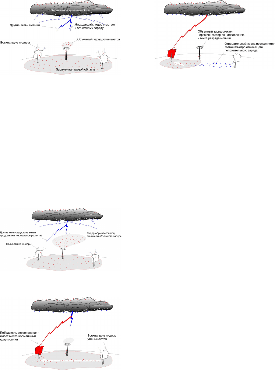
Чтобы понять сущность процесса фазы преры-
вания молниевого лидера, приближающегося к DAS,
необходимо понять состояние лидера перед касани-
ем объекта. Это продемонстрировано на рис. 1 –
схема, которая поможет понять работу DAS. Она
иллюстрирует процесс за миллисекунды до преры-
вания. Обратите внимание, что молния имеет не-
сколько ответвлений. Все примерно на одном рас-
стоянии от земли, одна должна коснуться поверхно-
сти. Целью является не дать ей коснуться DAS или
объекта в защищенной области. Рис. 1 иллюстрирует
эту ситуацию на примере мачты, защищенной DAS.
DAS реагирует на приближение лидера увеличением
плотности объемного заряда.
524
Рис. 2. Ветвь молнии приближается к DAS.
Рис. 2 показывает реактивный пространственный
заряд, созданный приближающейся ветвью молниевого
лидера. Результирующий плотный объемный заряд
подавляет формирование встречного лидера и ситуация
развивается, как показано на Рис. 4, а затем – на Рис.5.
На Рис. 4 одна ветвь теперь касается дерева, все ос-
тальные стримеры замкнуты. И наконец, объемный
заряд, сформированный DAS, также замыкается через
ионизатор, создавая обратный разрядный ток, продол-
жающийся только несколько миллисекунд. Все заряды,
содержащиеся в ветвях и вокруг ионизатора, принима-
ют участие в процедуре нейтрализации, как показано
на Рис.5. Земля возвращается к нормальному отрица-
тельному состоянию, когда грозовые области разряжа-
ются или уходят.
Рис.3. Реактивный объемный заряд, созданный
приближающимся лидером.
Рис. 4 Молниевая ветвь касается дерева. Ос-
тальные ветви уходят.
Рис.5. Заряд уходит в молниевый канал. Уста-
новка возвращается в нейтральное состояние.
Процесс втягивания занимает от одной до трех
миллисекунд. Это соответствует примерно 100 мКл
(0,1 А с). Тем не менее, результирующая скорость
может достигать от 30 до 100 кА/мс. В то же время
этот обратный ток не несет никакой разрушительной
энергии, т.к. передается очень маленький заряд за
очень короткий промежуток времени.
Защищенная область
Из принципов работы DAS вытекают три фак-
тора, влияющие на размер и форму защищенной об-
ласти:
1. Количество ветвей молниевого разряда;
2. Расстояние между ветвями;
3. Удаленность DAS от нисходящего лидера.
Количество ветвей лидера определяет вероят-
ность того, что одна из них приблизится к установке
DAS. Обычный лидер стартует и производит не-
сколько ветвей; тем не менее, к моменту, когда он
достигнет расстояния нескольких сот метров от зем-
ли, количество ветвей многократно увеличивается,
как показано на Рис. 2. Поэтому вероятность удара
молнии в одну из незащищенных DAS точек равна
один к количеству ветвей молнии.
Таким образом, DAS задерживает развитие при-
ближающегося лидера-ветви с целью переноса удара
в другое место.
Заключение
О состоятельности тех или иных научных ут-
верждений можно судить на основании опыта их
применения. Статистика работы DAS формировалась
на протяжении 34 лет на более чем 2400 объектах, и
ее наработка составляет более 30 000 системных лет
работы. Репрезентативность этой выборки не может
вызывать сомнений.
Одним из подтверждений могут служить ре-
зультаты шестилетних наблюдений с мая 1995 по
май 2001, производимых на атомной электростанции
Browns Ferry Nuclear Plant (Алабама, США). Иониза-
тор был установлен на трубу станции высотой более
180 м. На рис. 6 и 7 показаны результаты наблюде-
ний ударов молний в радиусе 500 м и 5 км за три
года до установки ионизатора и три года спустя. Чи-
словые значения показаны в таблице 1. Как видно из
таблицы наблюдается снижение количества ударов
молний на 80% в радиусе 500 м от места установки
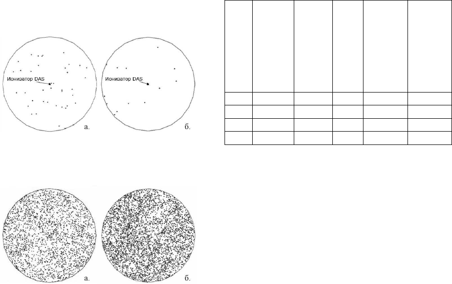
525
ионизатора на фоне общего увеличения молниевой
активности в радиусе 5 и 10 км.
Рис. 6. Молниевая активность в радиусе 500 м
от трубы в течении 3-х лет до (а) и трех лет после (б)
установки DAS.
Рис. 7. Молниевая активность в радиусе 5 км от
трубы в течении 3-х лет до (а) и трех лет после (б)
установки DAS.
Рас
сто-
яни
е,
км
Кол-во
ударов
до ус-
танов-
ки DAS
Кол-во
ударов
после
уста-
новки
DAS
Из-
мене
ние
%
Ожи-
даемое
количе-
ство
ударов
Изме-
нение,
приве-
денное
к ожи-
даемо-
му,
%
0,5 40 13
-68
66
-80
5 2630 4327 +65 4327 0
10 11277 18688 +66 18688 0
16 33685 55199 +64 55199 0
Таблица 1. Количество ударов молний в течение
трех лет до и трех лет после установки DAS.
Литература
1. Черкасов В.Н. Защита взрывоопасных со-
оружений от молний и статического электричества. –
М.: Стройиздат, 1984 – 81 с.
2. Надточин В.И. Анализ причин аварии на ре-
зервуаре РВС 20000 №22 Александровской НПС ма-
гистрального нефтепровода «Александровское –
Анжеро – Судженск» // Безопасность труда в про-
мышленности.
3. Preventing direct strikes Roy B. Carpenter, Jr.
Lightning Eliminators & Consultants, Inc. August 2005.
4. Lightning Strike Protection By Roy B. Carpen-
ter, Jr. Mark M. Drabkin, PhD. Lightning Eliminators &
Consultants, Inc. 2005
5. Moore, Charles B., “Results of the Lightning
Strike Contest,” Langmuir Lab, June 2001,
(unpublished).

526
DETAILS INCLUDED IN THE CALCULATION
OF GEOMAGNETICALLY INDUCED CURRENTS
N ELECTRIC POWER TRANSMISSION NETWORKS
R.
J.
P
IRJOLA
1,2
,
F
INLAND
,
D.
H.
B
OTELER
2
,
C
ANADA
,
L.
T
RICHTCHENKO
2
,
C
ANADA
,
M.
W
IK
3
,
S
WEDEN
1
Finnish Meteorological Institute, Helsinki, Finland,
2
Natural Resources Canada, Ottawa, Canada,
3
NeuroSpace, Malmö, Sweden, email: risto.pirjola@fmi.fi
Abstract. Geomagnetic storms create a geoelectric field on the ground as described by Faraday’s law of induction.
The geoelectric field drives geomagnetically induced currents (GIC) in technological conductor systems, such as
electric power transmission networks. Generally GIC are a source of problems to the system, which occur due to
saturation of transformers in power grids. GIC can be investigated by measurements or by theoretical modelling. If
the geoelectric field is (assumed to be) known, the computation of GIC in a power system is in principle
straightforward by applying formulas that include the earthing impedance matrix and the network admittance
matrix determined by the network resistances and topology. However, to our experience, some parts of the power
grid data always remain unknown in practice, so sensitivity analyses have to be performed to estimate the effect of
inaccuracies of different quantities on calculated GIC values. GIC can naturally flow everywhere in a galvanically-
connected network, which means, for example, that in autotransformers GIC enter from one voltage level to
another. Therefore autotransformers require special modelling techniques in connection with GIC computations.
Particular care is also needed in the case of two-winding transformers when two (or more) voltage levels are
included in the GIC modelling. In this paper, we discuss all these details appearing in calculations of GIC and
consider our conclusions and solutions.
Introduction
“Space Weather”, which is driven by solar activity,
concerns electromagnetic and particle conditions in the
near-Earth space, e.g. [1]. The consequences of a burst on
the Sun are carried by the solar wind to the Earth, at which
the geomagnetic field interacts with the solar wind.
Finally, this leads to intense and rapidly-varying electric
currents in the Earth’s magnetosphere and ionosphere, i.e.
a space weather storm occurs. The physical processes
associated with space weather are complicated and not yet
fully known, so research must be continued.
Space weather can disturb and even damage
permanently technical equipment in space and on the
ground, which may cause considerable problems to reliable
functioning of the society. The magnetospheric-ionospheric
currents produce a geomagnetic disturbance or storm at the
Earth’s surface. In accordance with Faraday’s law, it
induces a geoelectric field, which drives currents, called
geomagnetically induced currents (GIC), in conductors,
such as electric power transmission networks, oil and gas
pipelines, telecommunication cables and railway circuits. It
is interesting to note that the first GIC observations were
already made much before the beginning of modern space
weather science, i.e. in early telegraph devices in the mid-
1800’s [1,2]. Today, however, power networks, which are
the focus of this paper, constitute the most significant
systems regarding GIC.
In general, GIC, which have typical variation times
from seconds to minutes and hours being thus (quasi-)dc
currents compared to the 50/60 Hz ac frequency, are a
possible source of problems in power networks. The
problems result from half-cycle saturation of
transformers, e.g. [3].
GIC in a network of conductors can be studied by
measurements, e.g. [4], and by model calculations,
which should preferably be verified and adjusted by
recorded GIC data. This paper is concentrated on
theoretical model calculations of GIC in power systems.
Two separate parts can be distinguished when computing
GIC in a power grid (or in any network):
1) Determination of the horizontal geoelectric field
2) Calculation of GIC in the network produced by
the geoelectric field.
The first part is naturally independent of the network
considered. In principle, it requires knowledge of the
Earth’s conductivity structure and of the
magnetospheric-ionospheric currents. The geoelectric
field is then obtained by using Maxwell’s equations and
electromagnetic boundary conditions. In practice,
however, knowledge of space currents is not necessary if
geomagnetic variation data at the Earth’s surface are
available. In this paper, we address the second part and
refer to [5] regarding the first part.
In the next section, the technique applicable to the
second part of a GIC calculation is summarised. It is
followed by sections devoted to possible uncertainties
included in GIC computations and to the need of special
modelling of autotransformers and two-winding
transformers.
Calculation of GIC in a power network
Due to the (quasi-)dc nature of GIC, a dc treatment
can be applied to the determination of GIC driven by the
geoelectric field, i.e. in the second part of a GIC
calculation. For a power network with N stations, we
define an N × N earthing impedance matrix Z
e
including
527
the earthing resistances of the stations and an N × N
network admittance matrix Y
n
determined by the
transmission line resistances. By utilising these matrices,
it is possible to derive the following formula for the N ×
1 column matrix I
e
whose elements are GIC flowing into
(from) the Earth at the stations:
I
e
= (1+Y
n
Z
e
)
–1
J
e
(1)
If the stations are distant enough, making the
influence of GIC at one station on the voltages at other
stations negligible, Z
e
is diagonal with the elements
equalling the station earthing resistances For additional
details, we refer, for example, to [6,7,8]. In equation (1),
the symbol 1 refers to an N × N unit matrix, and the N ×
1 column matrix J
e
includes the input from the
geovoltages obtained by integrating the geoelectric field
between the stations. Generally, the geoelectric field is
rotational making the integration path-dependent, and the
geovoltages must be computed along the transmission
lines, e.g. [9,10]. However, it should be noted that a
spatially uniform geoelectric field, which is often
assumed to get an overview of the GIC flow in a
network, is irrotational implying an independence of the
choice of the path in the computation of geovoltages.
Equation (1) shows that if the earthings are perfect, i.e.
Z
e
= 0, I
e
and J
e
are equal.
When applying equation (1) to a three-phase power
network, the three phases are usually, including this
paper, treated as one circuit element, whose resistance is
one third of that of a single phase. Correspondingly, a
GIC value in a circuit element is three times the current
in a single conductor. The (total) earthing resistances of
the stations are often, including this paper, defined to
consist of the actual earthing resistances, of the
transformer resistances, and of any other resistances in
the earthing leads of transformer neutrals with all these
resistances connected in series.
A simple formula for GIC in transmission lines also
exists [6,7]. Regarding scientific and physical
significance, GIC between the network and the Earth and
in the lines are equivalent, but in practice, the former are
more important because they are responsible for the
possible transformer saturation. Moreover, measured
GIC data are usually collected in earthing leads of
transformer neutrals [4].
Inaccuracies in power network data
Besides the horizontal geoelectric field, the
following power network data are needed for the second
part of a GIC calculation [11]:
-Coordinates of the stations
-Total earthing resistances of the stations
-Transmission line resistances
-Network topology and configuration
-Precise information of the connections at the stations
-Information of possible series capacitors
The calculation of GIC from the input data is based
on Ohm’s and Kirchhoff’s laws. Thus, in principle, the
calculation is exact. However, in practice, the geoelectric
field values suffer from approximations, and the power
network data also include inaccuracies and
shortcomings. The latter can be caused by difficulties in
disclosing confidential network information or simply by
insufficient knowledge, and they concern uncertainties in
station locations, unknown resistance values,
approximations when considering autotransformers,
undocumented connections or disconnections of
transmission lines, etc. Consequently the second part of a
GIC calculation remains approximate as well.
It can be shown that uncertainties in earthing
resistance data of even tens of per cent, as well as
inaccuracies of station locations in the kilometre range,
are generally not critical for calculated GIC values in a
power grid [11,12]. This is particularly true if average
values over all sites of the network are considered.
The study presented in [11] indicates that, even
though the overall average impact of a connection or
disconnection of one or two transmission lines on GIC in
a power grid is not large, inadequate knowledge of
connections and disconnections can lead to totally
incorrect calculated GIC values at some sites and thus, in
the worst case, to completely inappropriate
countermeasures for avoiding GIC problems.
Values of possible non-zero off-diagonal elements
of the matrix Z
e
, which describe the interaction between
the stations of a power network, are not easy to be
determined. Fortunately, both [12] and [13] support that
the effects of non-zero off-diagonal elements on GIC
values are not large. Thus, probably, if necessary, Z
e
may be regarded as diagonal without getting unusably
erroneous results.
GIC can naturally flow throughout a galvanically-
connected network. Thus, an exact GIC calculation
would require the whole network to be taken into
account. However, the usual situation is that a GIC study
is focussed on a limited area only. It is shown in [14,15]
that GIC do not flow over very long distances in a power
grid. This means that, in a practical study, we need not
extend the network considered far beyond the area of
interest, which, of course, simplifies the calculations.
Although equation (1) looks simple in the particular
matrix form, it includes a lot of parameters coupled together
in complicated ways when a real power network is
considered. Therefore, mathematically precise analytic
investigations of the effects of inaccuracies in power
network data are not possible in practice. The above-
mentioned conclusions of the effects are also based on
numerical studies. The old Finnish 400 kV power network
introduced as a GIC calculation test model in [8] is suitable
for investigating effects of inaccuracies in network data on
GIC values and for testing different GIC calculation
algorithms. It consists of 17 stations and 19 transmission
lines being thus large enough to be realistic but not too large
to unnecessarily complicate GIC computations.
528
Modelling autotransformers and two-
winding transformers
In autotransformers, the higher and lower voltage
networks are in galvanic connection, so the flow of GIC
from one voltage level to another is possible. This means
that even if GIC are only studied in the grid of one
voltage (e.g. 400 kV in Finland or Sweden) the existence
of autotransformers makes the lower voltage grid(s) play
a role, too. If GIC are investigated in a power network
having two (or more) voltage levels then two-winding
transformers must be taken into account as well.
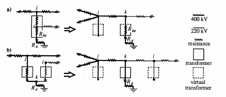
Fig. 1: Modelling of an autotransformer (a)
and a two-winding transformer (b) for GIC
calculations [14,16]. For clarity, one phase of the
three-phase system is only included in the
diagram.
Fig. 1 adopted originally from [16] depicts a
technique for describing an autotransformer and a two-
winding transformer in a manner applicable to the GIC
calculation method governed by equation (1). (Note that,
in order to keep the diagram clear enough, only one
phase is plotted in Fig. 1.) The symbols R
ke
and R
e
refer
to the resistance of the common lower voltage winding
in an autotransformer and to the actual station earthing
resistance, respectively. In the case of an autotransformer
(a), the high voltage node j becomes a “virtual station”
earthed through an infinite resistance, and the series
winding is treated as a transmission line between
“stations” j and k. In the case of a two-winding
transformer (b), both the high voltage node j and the low
voltage node l become “virtual stations”, and the
windings are regarded as transmission lines between
“stations” j and k and k and l, respectively.
In a modelling of this kind, the “stations” j, k and l
are very near each other, in fact at the same site. Thus,
the earthing impedance matrix Z
e
would seem to have
non-zero off-diagonal elements. We may conclude the
following values for the elements of Z
e
that are related to
Fig. 1 [14,16]:
Z
e,jj
=
,
Z
e,kk
=
R
ke
+
R
e
,
Z
e,jk
=
Z
e,kj
=
R
e
(1a – auto) (2)
and
Z
e,jj
=
Z
e,ll
=
,
Z
e,kk
=
Z
e,jk
=
Z
e,kj
=
Z
e,kl
=
Z
e,lk
=
Z
e,jl
=
Z
e,lj
=
R
e
(1b – two-winding) (3)
Looking at Fig. 1b more carefully indicates that,
although the description included in the figure and in
formulas (3) is correct, it is evident that a two-winding
transformer can be modelled in a simpler way by
ignoring the node k and using only “stations” j and l,
which are not connected to each other. Denoting the
winding resistances of the transformers at j and l by R
t,j
and R
t,l
, respectively, the elements of Z
e
associated with j
and l are
Z
e,jj
=
R
t, j
+
R
e
,
Z
e,ll
=
R
t,l
+
R
e
,
Z
e,jl
=
Z
e,lj
=
R
e
(4)
Besides theoretical reasoning, we have “proved” this
simplification by numerical calculations as well.
Our recent investigations, based on theoretical
conclusions, numerical computations and considerations
of a simple dc circuit for analogy, indicate the that the off-
diagonal elements of Z
e
connected with a “virtual station”,
such as j in Fig. 1a and j and l in Fig. 1b do not affect GIC
values in a network. Consequently, referring to equations
(2) and (3), we can replace R
e
as the value of the off-
diagonal elements with zero (or with any other value).
Concluding remarks
After the geoelectric field is known, GIC in a power
network can in principle be calculated exactly in a
straightforward manner by using dc circuit theory.
However, in practice, approximations are necessary,
which may result, for example, from incomplete power
grid data or from the impossibility of considering the
whole galvanically-connected network where GIC can
flow. In this paper, we summarise some rules of thumb
necessary to be kept in mind when making
approximations in GIC calculations. Special attention is
paid to the modelling of autotransformers and two-
winding transformers.
Information about the authors
Dr Risto Pirjola (FMI & NRCan) and Dr David
Boteler (NRCan) have carried out scientific research on
GIC and geoelectromagnetics for more than 30 years. Dr
Larisa Trichtchenko joined NRCan in the 1990’s. Her
scientific interests include space weather forecasting,
magnetospheric physics and GIC. Dr Magnus Wik runs
his own company NeuroSpace since 2009, whose
activities concern space weather, GIC and solar
phenomena.
References
1. L. J. Lanzerotti, D. J. Thomson, and C. G.
Maclennan, “Engineering issues in space weather,”
529
Modern Radio Science 1999, M. A. Stuchly (ed.),
International Union of Radio Science (URSI), Oxford
University Press, pp. 25-50, 1999.
2. D. H. Boteler, R. J. Pirjola, and H.
Nevanlinna, “The effects of geomagnetic disturbances on
electrical systems at the Earth’s surface,” Adv. Space
Res., Vol. 22, pp. 17-27, 1998.
3. J. G. Kappenman, “Geomagnetic
Disturbances and Impacts upon Power System
Operation,” The Electric Power Engineering Handbook,
2nd Edition, edited by L. L. Grigsby, CRC Press/IEEE
Press, Chapter 16, pp. 16-1 - 16-22, 2007.
4. A. T. Viljanen, R. J. Pirjola, K. M. Pajunpää,
and A. A. Pulkkinen, “Measurements of geomagnetically
induced currents by using two magnetometers,”
Proceedings of the 8-th International Symposium on
Electromagnetic Compatibility and Electromagnetic
Ecology, Saint-Petersburg, Russia, June 16–19, 2009, pp.
227-230, 2009.
5. A. Viljanen, A. Pulkkinen, O. Amm, R.
Pirjola, T. Korja, and BEAR Working Group, “Fast
computation of the geoelectric field using the method of
elementary current systems and planar Earth models,”
Ann. Geophys., Vol. 22, No. 1, pp. 101-113, 2004.
6. M. Lehtinen, and R. Pirjola, “Currents
produced in earthed conductor networks by
geomagnetically-induced electric fields,” Ann. Geophys.,
Vol. 3, No. 4, pp. 479-484, 1985.
7. R. Pirjola, “Calculation of geomagnetically
induced currents (GIC) in a high-voltage electric power
transmission system and estimation of effects of
overhead shield wires on GIC modelling,” J. Atmos. Sol.
Terr. Phys., Vol. 69, Issue 12, pp. 1305-1311, 2007.
8. R. J. Pirjola, “Properties of matrices included
in the calculation of geomagnetically induced currents
(GICs) in power systems and introduction of a test model
for GIC computation algorithms,” Earth, Planets and
Space, Vol. 61, No. 2, pp. 263-272, 2009.
9. D. H. Boteler, and R. J. Pirjola, “Modelling
Geomagnetically Induced Currents produced by Realistic
and Uniform Electric Fields,” IEEE Transactions on
Power Delivery, Vol. 13, No. 4, pp. 1303-1308, 1998.
10. R. Pirjola, “Geomagnetically Induced
Currents During Magnetic Storms,” IEEE Transactions
on Plasma Science, Vol. 28, No. 6, pp. 1867-1873, 2000.
11. R. J. Pirjola, “Effects of inaccuracies in
power network data on calculations of geomagnetically
induced currents,” Proceedings of the 8-th International
Symposium on Electromagnetic Compatibility and
Electromagnetic Ecology, Saint-Petersburg, Russia, June
16–19, 2009, pp. 231-234, 2009.
12. R. Pirjola, “Study of effects of changes of
earthing resistances on geomagnetically induced currents
in an electric power transmission system,” Radio
Science, Vol. 43, No. 1, RS1004, doi:
10.1029/2007RS003704, 13 pp., 2008.
13. R. Pirjola, “Effects of interactions between
stations on the calculation of geomagnetically induced
currents in an electric power transmission system,”
Earth, Planets and Space, Vol. 60, No. 7, pp. 743-751,
2008.
14. R. Pirjola, “Effects of space weather on high-
latitude ground systems,” Adv. Space Res., Vol. 36, Issue
12, doi: 10.1016/j.asr.2003.04.074, pp. 2231-2240, 2005.
15. R. J. Pirjola, “On the flow of geomagnetically
induced currents in an electric power transmission
network,” Canadian Journal of Physics, Vol. 88, No. 5,
pp. 357-363, 2010.
16. T. Mäkinen, “Geomagnetically induced
currents in the Finnish power transmission system,”
Finnish Meteorological Institute, Geophysical
Publications, No. 32, Helsinki, Finland, 101 pp., 1993.

530
RESPONSES OF POWER SYSTEMS TO THE NATURAL GEOMAGNETIC
VARIATIONS AT DIFFERENT LATITUDES
L.
T
RICHTCHENKO
1
,
D.
H
OLT
1,2
,
R.
P
IRJOLA
1,3
CANADA
1
Geomagnetic Laboratory, Natural Resources Canada, e-mail: ltrichtc@nrcan.gc.ca;
2
University of Waterloo, Canada,
3
Finnish Meteorological Institute, Finland
Abstract. Impacts of the natural low-frequency electromagnetic fluctuations (geomagnetic storms) on power
grids can be significant enough to cause equipment damage or even power blackouts. In order to prevent
these damaging impacts, the effective procedures should be placed based on the assessments of the geomag-
netically induced currents (GIC) in power grids and their interference with the essential equipment.
The GIC sizes are influenced by the amplitude of the geomagnetic field variations, ground conductivity
structure, and topology and characteristics of the affected network. Also, it is anticipated that the northern
networks would experience larger GICs due to their location in the auroral zone, where the rate of occur-
rence of the geomagnetic storms is larger. It will be shown that the network configuration plays its role in
the GIC distribution over the power grid and proper network modelling is important component for the as-
sessment of the geomagnetic hazard to power grids.
Introduction
Importance of the safety and security of electricity
supplies in modern world is hard to overestimate. Sev-
eral high-level documents and presentations emphasizing
the role of assessment and mitigation of the negative
impacts of geomagnetic storms on critical technology
have appeared almost simultaneously at the high gov-
ernmental levels in North America, UK and EU
[1, 2].
Thus, socio-economic consequences of the vulner-
ability of the power grids to the geomagnetic storms
make the GIC-research of primary importance, espe-
cially in the view of the upcoming increase in solar ac-
tivity and, thus, increase in the possibilities to have more
geomagnetic storms.
In this paper we describe the general methodology
for assessment of GIC effects on power grids and give
more detailed estimations of the importance of each step
in GIC modelling. As examples, we use GIC data and
modelling results for North American power grids lo-
cated at different latitudes.
GIC Assessment
In power systems, geomagnetically induced currents
(GIC) flow through the transformer windings at
transformer substations, producing extra magnetisation
which can saturate the core of the transformers causing
increased harmonics. This results in transformer heating,
malfunctioning of relays and other equipment on the
system and leads to problems ranging from trip-outs of
individual lines to collapse of the whole system.
The amplitude of the GIC variations due to
geomagnetic interference depends on: (1) the geoelectric
field which drives GIC in power grids, and (2) the details
of the power network (resistance to ground, topology,
orientation, number of transformers at each substation
and their types). Thus, in order to properly assess the
possible damage from geomagnetic hazards, detailed
modeling of the system is needed.
Modelling of the GIC is usually supported and
verified by GIC data measured in several key points of
the system.
The first part of the modelling is to define the
geoelectric fields in the ground. Unfortunately, there are
no regular recordings of this field and therefore,
modelling of the geoelectric field using the closest to the
power grid geomagnetic field observations together with
models of the Earth surface inpedance is widely used in
geophysics, magnetotelluric applications and for GIC
modelling [3-5].
We use the geomagnetic coordinate system with axis
x north, y east, and z vertically downwards. For the fre-
quency range of 1sec to 24 hours and earth resistivity
range 1 to1000 Ohm-m, displacement currents are small
in comparison with conductivity currents. Therefore,
electric and magnetic fields in the frequency domain can
be given by the diffusion equations [3]. For our case,
when the magnetic field at the surface of the earth (1st
layer) is known from the magnetic observations, the
electric field (E
surface
) can be obtained from (1.. Here the
surface impedance (Z
surface
) is the ratio of magnetic (H)
and electric fields mesured during magnetotelluric
surveys or inferred from a literature review [6].
surfacesurfacesurface
HZE =
(1)
The impedance at any layer
n
can be found by apply-
ing the recursion relation for the impedance of an
n
- lay-
ered half-space [5].
( )
)2(
1
1
2
2
+
−
=
−
−
nn
nn
dk
nn
dk
n
n
erk
er
iZ
ωµ
where
d
n
,
k
n
are the thickness and propagation con-
stant
ωµσ
ik =
of the layer
n
, in case of the surface
impedance the layer number is
n
=1 ;
r
n
is the reflection
coefficient at each layer and can be obtained from