Yang J., Poh N. (ed.) Recent Application in Biometrics
Подождите немного. Документ загружается.


Biometric Application in Fuel Cells and Micro-Mixers
289
Parallel Bionic Net Serpentine
χ
0.5 0.535 0.372 0.046
A
Rea
0.001438 0.001324 0.001 0.001512
Rea
A
χ
347.7 404.08 372 30.423
Table 2. Performance Index Versus Four Kinds of Flow Slabs at Re=100. Source: Wang et al.,
(2009)
2.2 Biometric flow slab applied to PEMFC (Wang et al., 2010)
As for the bipolar plates, they are one of the most important and expensive components of
PEM fuel cells because they account for more than 60% of the total weight and 30% of the
total cost of the system. Therefore, improving or addressing a novel flow slab design seems
to be workable to improve these issues with respect to the weight, volume and cost. In this
work, two kinds of novel biophysical flow slabs, namely BFF1 and BFF2, originating from
the prototype of the biophysical flow slab shown in Figure 1, and due to their possession of
a lower pressure drop and excellent flow uniformity, (Wang et al., 2009) shown in Figures 2
and 3,would be utilized in PEMFCs (Wang et al., 2010). They would then be compared with
the two convectional flow slabs, the serpentine and parallel, which would be used for the
investigation of cell performance.
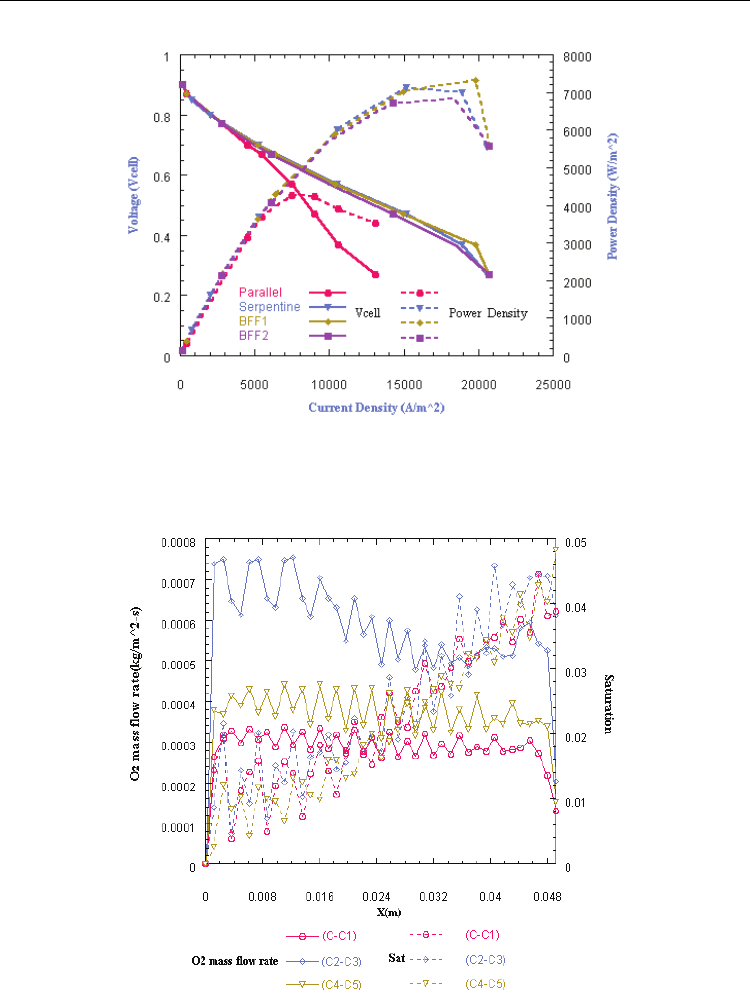
The I–V cell polarization curves and I–W cell power density curves of the parallel,
serpentine and two new biometric flow slabs were the first investigated and are shown in
Figure 4. The results in Figure 4 show that serpentine and two biometric flow slabs (BFF1
and BFF2 ) have the appearance of a better performance than that of the parallel flow slab.
The limited current densities at V
cell
=0.27 for the serpentine, BFF1, and BFF2 compared
with the parallel flow slab are increased by the amount of 58.19%, 58.48%, and 57.13%,
respectively. When the operating voltage is lower than 0.57V, the performance of the
parallel flow field seems to increase much more slowly than other flow slabs. This is because
of its strong dependence on the distribution of the oxygen mass flow rate at the cathode
GDL–CL interface, and a high oxygen mass flow rate will cause more oxygen to enter the
CL for the electrochemical reaction.
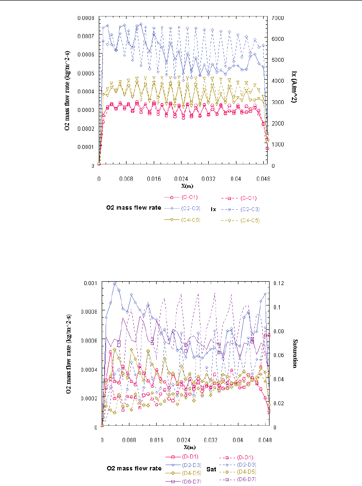
Figure 5 shows the distribution and relation between the oxygen and liquid water at the
three segments C-C1, C2-C3 and C4-C5 for BFF1. As the oxygen mass flow rate increases,
the amount of liquid water from inlet to outlet decreases. The amounts of oxygen at the
cross-section C-C1 and C4-C5 are less than C2-C3, resulting in lower current densities. Some
baffles could be used and applied to promote the mass transport of C-C1 and C4-C5 in
future studies (Perng et al., 2009).
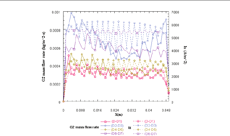
Figure 6 indicates clearly that the BFF1 flow slab will produce a higher uniform distribution
of current densities at the section of C-C1, C2-C3 and C4-C5. Hence, a higher performance
for BFF1 would be expected because a higher uniform distribution of current density is one
of the important factors for promoting the cell performance. Generally speaking, the lower
the pressure loss is, the higher the net performance of the cell will be (Perng et al., 2009). To
design a flow slab with a lower pressure drop, new flow slabs, named BFF1 and BFF2
respectively, were designed by the biophysical conception in this study.

Recent Application in Biometrics
290
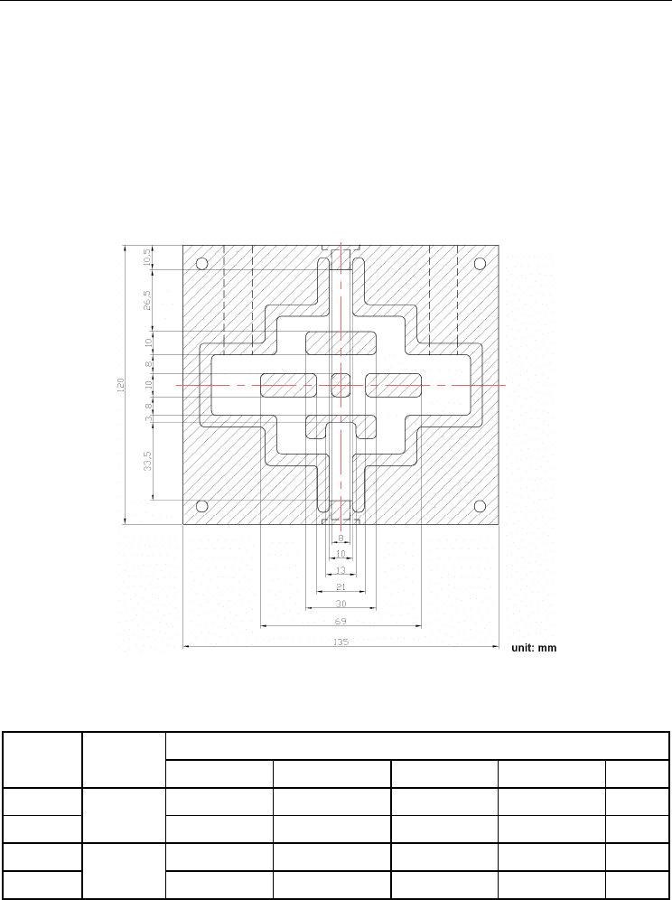
Figure 7 displays the distribution and relation between oxygen and liquid water at the cross-
sections of D-D1, D2-D3, D4-D5 and D6-D7 for BFF2. The trend of oxygen and liquid water
distribution of D-D1, D2-D3, D4-D5 referred to are similar to C-C1, C2-C3 and C4-C5 of
BFF1. The average oxygen distribution at the section of D6-D7, resulting from the shear
stress, would be found to be the highest. Figure 8 shows that BFF2 would possess a better
uniformity of flow distribution than BFF1. In addition, the shear stress would push more
oxygen into CL for an electrochemical reaction, thus a greater current at the cross-section of
D6-D7 could then be produced.
In this study, a pressure drop loss with respect to power density ( Perng et al., 2009 ),
defined in Equation (2), would be used to acquire a superior flow slab.
cha
p
total
PA V
W
A
Δ
= (2)
In this equation,
p
W represents the cathode pressure drop loss,
P
Δ
is the total cathode
pressure drop of the fuel cell, A
cha
is the cross-sectional inlet flow area of cathode, V is the
fuel velocity at the inlet of cathode, and A
total
is the reaction area. The pressure drop losses of
the cathode and output power of the cell, with respect to a parallel, serpentine, BFF1 and
BFF2 flow slab, would be calculated and listed in Table 3. Due to a high pressure drop in
channels, the W
net
of serpentine is lower than that of the BFF2 in spite of the fact that the
W
cell
of serpentine is higher than that of BFF2. In addition, the pressure drop of BFF2 is
lower than that of BFF1. Hence, the net power of the four kinds of flow slab would be
obtained and shown in Table 3. It shows that the novel biometric flow slab of BFF1 and BFF2
would have a better performance than that of the serpentine and parallel flow slabs (Wang
et al., 2010).
To sum up, the total pressure drop and the uniformity of flow distribution are two
important factors for flow slab design because of their significant influence on the
performance of the PEMFC. In this study, the two biometric flow slabs, BFF1 and BFF2,
addressed in this study would have a better cell performance than the serpentine and
parallel flow slabs because they possess a higher uniformity of flow distribution and a
stronger ability to remove the liquid water. The novel biometric flow slab would have an
enhanced cell power performance compared to the serpentine and parallel flow slabs. These
findings, with respect to biometric flow slabs, would be useful to improve the PEMFC and
could even be expanded to other cell types. (Wang et al., 2010).
Flow field type
△
P (Pa)
W
cell
(w/m
2
) W
p
(w/m
2
) W
net
(w/m
2
)
Parallel 248 3529 4.4 3524.6
Serpentine 5137 5583 91 5492
BFF1 2073 5593 37 5557
BFF2 730 5546 13 5533
Table 3. Estimation of Pressure Drop Losses at an Operating Voltage of 0.27V.
Source: Wang et al., (2010)

Biometric Application in Fuel Cells and Micro-Mixers
291
Fig. 2. Biophysical Flow Slab (BFF1). Source: Wang et al., (2010)
Fig. 3. Biophysical Flow Slab (BFF2). Source: Wang et al., (2010)
Recent Application in Biometrics
292
Fig. 4. The
I–Vcell and I–Wcell Curves for Types of Parallel, Serpentine, BFF1 and BFF2,
respectively.
Source: Wang et al. (2010)
Fig. 5. Oxygen Mass Flow Rate (kgm
-2
s) and Liquid Water Distributions at the sections of C-
C1, C2-C3, C4-C5 Related to 0.7V for BFF1.
Source: Wang et al., (2010)
Biometric Application in Fuel Cells and Micro-Mixers
293
Fig. 6. Oxygen Mass Flow Rate (kgm
-2
s) and Current Density Distributions (Am
-2
) at the
Sections of C-C1, C2-C3, C4-C5 Related to 0.7V for BFF1.
Source: Wang et al., (2010)
Fig. 7. Oxygen Mass Flow Rate (kgm
-2
s) and Liquid Water Distributions at the Sections of
D-D1, D2-D3, D4-D5, D6-D7 Related to 0.7V for BFF2.
Source: Wang et al., (2010)
Recent Application in Biometrics
294
Fig. 8. Oxygen Mass Flow Rate (kgm
-2
s) and Liquid Water Distributions at the sections of D-
D1, D2-D3, D4-D5, D6-D7 Related to 0.7V for BFF2.
Source: Wang et al., (2010)
2.3 Biometric flow slab applied to Microbial Fuel Cells (MFCs) (Wang et al., 2011)
In the academic studies of microbial fuel cells (MFCs), there is a significant absence of
sufficient discussion and research regarding to the design of flowchannels and flow-fields
(Hameler et al., 2006; Logan et al., 2004), and even less discussion as to why and how they
could be applied to MFCs. However, the research of flow channels being applied in fuel
cells have been proven to have a significant contribution to power performances (Wang et
al., 2009; Sabir et al., 2005), especially with regards to fuel efficiency and power density
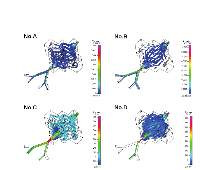
(Sabir et al., 2005). A new biometric flow channel, shown in Figure 9 and applied in rumen
microbial fuel cells (RMFCs), was first addressed by (Wang et al., 2011). Looking at Figure
10 and Table 4, the obstacle groups of No.A and No.C have a higher flow mixing efficiency
inside the chamber of RMFCs. The obstacles can cause flow to split and recombine to
enhance flow mixing. Since the Reynolds number is higher in the case of No.C, the flow
convection at the inlet entrance of RMFCs is more intensive than in the case of No.A and
also has a higher flow mixing. In Case No.D, without obstacles, flow separation is created
due to a high Reynolds number (Lashkov et al., 1992; Jadhav et al., 2009) and the Coanda
effect.
Therefore, proton exchange seems to be unevenly mixed because the main flow and the
separation flow are almost without interaction. In addition, the electron and proton from the
reactants will continue to be exhausted from the charged reaction of RMFCs, and finally
creates a concentration loss in some regions of the chamber. Conversely, Case No.B does not
experience that problem because of the lower Reynolds number, thus creating a smoother
flow and more even reaction. Even though the flow obstacles do not exhibit noticeable
benefits in the flow mixing, the effect on the flow field is overall beneficial to the electricity
Biometric Application in Fuel Cells and Micro-Mixers
295
system (Wang et al., 2009). This creates a better interaction on the surfaces of electrodes and
proton exchange membranes, thus avoiding concentration loss and proving more efficient
than flow fields that are uneven. In this study rumen microbes and plant fibers that acted as
substrates were utilized in single chambers in the cases of both using obstacles and different
Reynolds numbers respectively to investigate the power performance of RMFCs. The RMFC
system with a biometric flow channel (with obstacles), and at a higher Reynolds number
(Re= 496.18), will produce a higher power performance with a voltage potential and power
density of 0.716 V and 0.022mW/m
2
respectively. This is much better than in the cases
without obstacles showing a positive effect of a biometric flow channel on the power
performance of RMFCs.
Fig. 9. Geometrical Dimensions of a Biometric Flow Channel for RMFCs. Source: Wang et al.,
2011
MFCs Re No.
Flow mixing efficiency at analyzed positions (%)
a b c d e
No.A
19.85
99.6 99.8 99.8 99.7 99.8
No.B 99.0 99.3 99.0 99.3 99.4
No.C
496.18
99.8 99.8 99.9 99.7 99.9
No.D 100.0 100.0 100.0 100.0 100.0
Table 4. Flow Mixing Efficiency Versus Different Flow Conditions and Cross-sections
analyzed.
Source: Wang et al., 2011
Recent Application in Biometrics
296
Fig. 10. 3D Flow Velocity Images Versus Different Flow Conditions and Cross-sections
Analyzed (shown in Table 4).
Source: Wang et al., 2011
3. Biophysical micro-mixer (Wang et al., 2009)
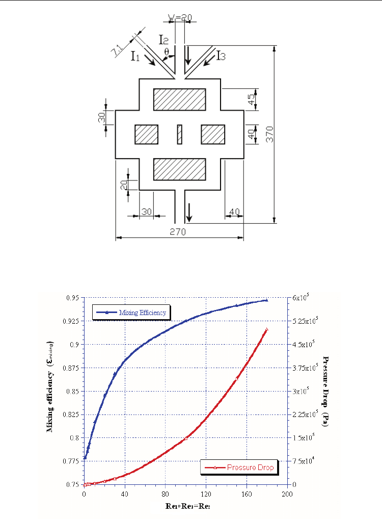
In this work, a biophysical concept was applied to passive micro-mixers, named as a
biophysical micro-mixer and shown in Figure 11, to promote mixing efficiency. The vertical
width of a channel would be gradually increased from 20 μm at the inlet to 40 μm at the
middle section of the device, and then gradually decreased along the flow downstream to
the outlet. During the flow transmission process, the flow would be split first and then
recombined with a flow motion. When the flow passes through the middle section of the
system, increasing interfaces were created exponentially by laminating the interfaces
continuously along the channel. In addition, the convection flow in the biophysical channels
had a high flow uniformity and low pressure drop to enhance the flow mixing (shown in
Figure 12). The mixing coefficient will approach 0.95 when the Reynolds number of the inlet
mid-channel is larger than 160. This result shows that the Reynolds number positively
affects mixing although it induces an increase in pressure drop (Wang et al., 2009).
Therefore, the prototype of a biophysical micro-mixer is simple and possesses a better

Biometric Application in Fuel Cells and Micro-Mixers
297
uniformity and lower pressure drop, so it can be expected to be useful to promote the
mixing performance of passive micro-mixers when the mixing distance is restricted. These
findings will be useful in the design of an optimal biophysical passive micro-mixer in
further research. Parameters, such as the Reynolds number ratio and aspect ratio and their
effect on mixing and pressure drop, required investigation because finding the optimal
Reynolds number ratio, Rer, and aspect ratio, AR, is important for the operation of the
micro-mixer.
To address the effect of the different inlet flow conditions on the mixing performance, a
parameter denoted as Rer defined in (3) was set for the Reynolds number ratio:
13
2
Re Re
Re
Re
r
+
=
(3)
Here, the operational Reynolds number defined in (4) was set in the range of Re=0.5 to 10:
Re
ave
UW
ρ
μ
=
(4)
Where
ρ
is the density of the fluid, U
ave
is the average velocity of the inlet channel; W, whose
value is 20 μm, represents the width of inlet channel I
2
and the outlet channel.
μ
is the
dynamic viscosity of the working fluid.
In addition, the aspect ratio,
AR, ranging from 0.5 to 10 is defined in (5) and was
investigated in order to study the sidewall effects on mixing performance:
D
AR
W
=
(5)
where
D is the depth of the channel and W is fixed at 20μm for the inlet at mid-channel.
Hence, the Reynolds number ratio was decided and based on the variations of inlet
Reynolds numbers from Re = 0.5 to 10 for the inlet channels. In addition, variations of aspect
ratio were set as 0.5, 1, 2 and 10 for determining the sidewall effect on mixing and pressure.
The results, shown in the Table 5, are addressed as follows:
First, the optimal Reynolds number ratio was Rer = 0.85, because of its outstanding mixing
performance at different aspect ratios. Second, the sidewall effect will influence the
variations in pressure drop and mixing performance, and increasing the AR will also
decrease the pressure. An optimal aspect ratio with the highest mixing effect was found at
AR = 2, which exhibited a good mixing for studied cases. In addition, the inlet angle of the
side-channels and its effect on mixing and pressure was considered in the design of the
micro-mixer. Hence, a variety of inlet angles of the side-channels, represented by θ, were
executed with Reynolds number ratios ranging from Rer = 0.5 to 2 in the case of Re2 = 1 and
its relationship to mixing performance and pressure drop are shown in Table 5.
The results of Table 6 show that a side-channel inlet angle of 30° was a better choice because
it possesses a better mixing effect and has a lower pressure drop. These findings will be
useful in the optimal design of a passive micro-mixer based on biophysical concepts in
further experimental studies.
Recent Application in Biometrics
298
Fig. 11. Prototype of a Biophysical Micro-mixer (unit: μm)
(Arrows indicate the inlet and outlet flow direction).
Source: Wang et al., (2009)
Fig. 12. Reynolds Number Effect Versus the Mixing and Pressure Drop at Rer = 1
Source: Wang et al., (2009)
