Wunderlich W. (ed.). Ceramic Materials
Подождите немного. Документ загружается.

Glass-Ceramics Containing Nano-Crystallites of Oxide Semiconductor 43
6050403020
ZnO
○ZnO
◇
α-Zn
3
B
2
O
6
▲KZn
4
B
3
O
9
Intensity (arb. units)
×1/4
×1/6
20C
595
19C
550
18C
570
21C
597
22C
590
2 (deg.)
Fig. 11. Bulk XRD patterns of the CaBZAK glass-ceramics whose chemical compositions are
listed in Table 3. Diffraction pattern of ZnO (JCPDS No. 00-021-1272) is also shown.
16001200800400
Wavenumber (cm
-1
)
Intensity (arb. units)
20
19
18
22
21
Fig. 12. IR spectra of the CaBZAK glasses (18–22)
Figure 12 shows IR spectra of the 10CaO-40B
2
O
3
-40ZnO-Al
2
O
3
-10K
2
O glasses (18–22).
Spectra are normalized using band around 1160 cm
-1
, which belongs to the B–O–B vibration
mode of the trigonal BO
3
unit. Band at 400~600 is attributed to ZnO
4
tetrahedra whereas the
band around 700 cm
-1
is assigned to the bending vibration of the B–O–B linkage. Band
attributed to ZnO
4
increased by addition of Al
2
O
3
. On the other hand, signals from 800 to
1200 cm
-1
that are assigned to tetrahedral BO
4
unit decrease with increasing amount of Al
2
O
3
.
Observed band attributable to B-O-B was shifted to longer wavelength with increasing
amount of Al
2
O
3
. The IR spectra of the glasses show that glass network has changed after
addition of Al
2
O
3
. Since Al
2
O
3
can make glass network, trigonal BO
3
unit that possess
weaker network than tetrahedral BO
4
unit increases by addition of Al
2
O
3
as a counterpart.
Concurrently, band attributed to ZnO
4
, which is similar structure of ZnO crystal, increased.
Thus, it is speculated that isolated ZnO
4
was formed in glass matrix after addition of Al
2
O
3
.
On the other hand, observed band around 1170 cm
-1
attributable to B-O-B was shifted to
longer wavelength with increasing amount of Al
2
O
3
. Since the stretching force constant of
Zn–O bond is lower than that of B–O, the frequency of Zn–O–B might appear at lower
region. Thus, it is suggested that observed shift by addition of Al
2
O
3
reflects the change
from Zn-O-B bond to B-O-B bond in the glass. The decrease of number of Zn-O-B bond will
affect the crystallization behaviour with precipitation of ZnO. That is a plausible
mechanism for precipitation of ZnO instead of -Zn
3
B
2
O
6
.
3.3 CaO-B
2
O
3
-ZnO-Al
2
O
3
-K
2
O-SiO
2
(CaBZAKS) Glass
Although we found that Al
2
O
3
affected the crystallization behaviour of glass-ceramics, there
was a limit of Al
2
O
3
content for vitrification of glass. To attain selective crystallization of
ZnO after heat-treatment, precipitation of -Zn
3
B
2
O
6
should be prevented. Since
homogeneous transparent glass was not obtained by addition over 12 mol% of Al
2
O
3
, we
used partially substitution of network former from B
2
O
3
to SiO
2
. Here, we called the CaO-
B
2
O
3
-ZnO-Al
2
O
3
-K
2
O-SiO
2
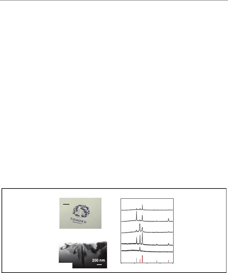
glass system as CaBZAKS. Figure 13A shows photograph of the
CaBZAKS mother glass (23) and the glass-ceramics (23C
610
). The obtained glass-ceramics
showed transparency despite of large difference of refractive index between ZnO and
surrounding glass matrix. Figure 13B shows TEM image of the CaBZAKS glass-ceramics
(23C
610
). Rod-like ZnO crystallites were precipitated from the surface of the sample, and the
crystal size was less than 1 m. It is noted that the obtained glass-ceramic shows
transparency despite a difference of refractive index, n, 0.4 between the precipitated ZnO
(~2.0) and surrounding glass matrix (1.59~1.63). Figure 13C depicts XRD patterns of several
CaBZAKS glass-ceramics (23C
610
, 24C
660
, 25C
660
, 26C
610
, and 27C
620
) together with diffraction
pattern of ZnO. Although diffraction intensities of each sample are different from the
JCPDS pattern, we have confirmed that ZnO was selectively crystallized in all cases.
ZnO
Intensity (arb. units)
23C
610
24C
660
25C
660
26C
610
27C
620
(100)
(002)
(101)
(102) (110)
A
10 mm
Mother
glass
23
Glass-
ceramic
23C
610
B
C
6050403020
200 nm
2 (deg.)
23C
610
Fig. 13. (A) Photograph of the CaBZAKS glass-ceramic (23C
610
) and the mother glass (23).
(B) TEM image of the CaBZAKS glass-ceramic (23C
610
). (C) XRD patterns of several
CaBZAKS glass-ceramics together with JCDPS pattern of ZnO.
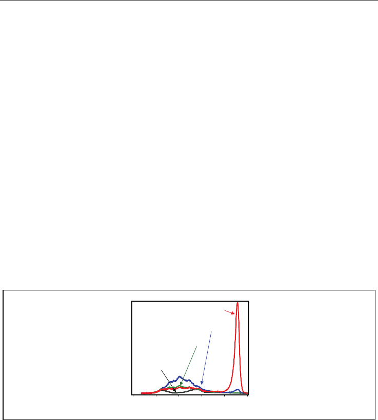
We have found the emission property of the ZnO precipitated glass-ceramics similar to that
of ZnO single crystal. Figure 14 shows photoluminescence spectra of the ZnO glass-
ceramics (23C
600
, 23C
610,
and 23C
640
) and the mother glass (23). The spectra were measured
at room temperature using a He-Cd laser as a light source.
The glass-ceramic 23C
640
was
opaque because of scattering by surface crystallized ZnO.
The glass-ceramic shows emission
Ceramic Materials 44
at 3.28 eV, which is assigned to free exciton emission of ZnO. The emission spectrum of
ZnO glass-ceramic is similar to that of ZnO single crystal. It indicates that crystal growth of
ZnO occurred enough to show the exciton emission. We can find several characteristics in
the obtained emission spectra of the ZnO glass-ceramics and the mother glass. The mother
glass roughly consists of two broad bands at 1.4~2.6 eV. The emission at 1.4-2.6 eV is
attributable to oxygen vacancies of ZnO (Vanheusden et al., 1996, Djurisic et al., 2007). On
the other hand, the intensity of emission at 3.28 eV, which is assigned to free exciton
emission of ZnO, clearly observed in the glass-ceramic. Since the thickness of crystallized
region in the ZnO-precipitated glass-ceramics was about 1 m from the surface, the volume
percentage of ZnO crystals shown in Fig. 14 was less than 1 volume %. The results indicate
that emission from the glass-ceramics depends on the state of precipitated ZnO crystallites,
and that unique property of ZnO can be equipped in the glass-ceramics by optimized
crystallization process (Masai et al., 2009).
In summary, we have obtained transparent ZnO-precipitated glass-ceramic. The ZnO nano-
crystallites that were precipitated at the surface of the glass showed both broad emission
and free exciton emission. The observed emission depends on the precipitated state of ZnO
in the glass matrix, and has great potential for optical devices. The large n between ZnO
crystallites and the surrounding glass matrix warrants the localization of photon, which is
also attractive as optical ceramic devices. Note that crystallization behaviour, such as
orientation of precipitated phase, or size of crystallites, in the glass matrix can be controlled.
The present ZnO glass-ceramics could be an attractive functional material using the
advantage of the amorphous glass material, which is quite different from conventional ZnO
material.
3.53.02.52.01.51.0
Photon energy (eV)
Signal intensity (arb. units)
Glass-ceramic (23C
610
)
Mother glass 23
Glass-ceramic (23C
640
)
Glass-ceramic (23C
600
)
Fig. 14. Photoluminescence spectra of ZnO glass-ceramics (23C
600,
23C
610
, and 23C
640
) and the
mother glass (23) using a He-Cd laser as a light source.
4. Current and Future Trends in Glass-Ceramics
Our results above-mentioned were achieved by examination of both the chemical
composition and the crystallization process by traditional heat-treatment using electric
furnace. Since the crystallization of glass by conventional heat-treatment is based on the
self-organization of crystal above the T
g
, the crystallization technique is favourable for
industrial process in which simplified process and mass production are required. However,
the method is not suitable for microstructuring of glass-ceramics consisting of locally
crystallized region at less than micrometres. Recently, there have been many reports on
another process for space selective crystallization: laser-induced crystallization. The
crystallization has been attained by several kinds of lasers, such as ultra-fast (e.g. femto-
second) pulsed laser (Kondo et al., 1998, Yonesaki et al., 2005), nano-second pulsed laser
(Fujiwara et al., 2002, Mizuno et al., 2006, Masai et al., 2008), or continuous wave (CW) laser
(Sato et al., 2001, Honma et al., 2003 & 2006). Laser irradiation can induce a geometrically
selective structural change, which is quite different from uniform bulk structural change
caused by a conventional heating process using a furnace.
If laser irradiation can induce a
change of refractive index or crystallization in a glass matrix, such laser-induced structures
provide unique properties without temporal decay. However, there is a difference between
a femto-second laser and a nano-pulsed laser and a CW laser from the view point of the
mechanism of laser-induced change in the irradiated material. The former can induce local
changes with little thermal effect whereas the latter two actively exploits the thermal effect
for laser-induced change.
If we use the crystallization of oxides for functionalization of glass,
control of the thermal process should be necessary. Irradiation of glass materials with a
laser having a thermal effect, therefore, is thought to be effective in preparing functional
devices using controllable crystallization behaviour. In using a thermal effect for a laser-
induced structural change, the change depends on temperature and holding duration above
the T
g
. If we can control the temperature and a holding duration of the temperature, we can
control the formation of crystallite nuclei and the growth of crystallites the respective, which
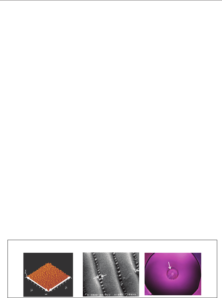
is of great importance in creating tailored local structures. For example, nano-second pulsed
laser irradiation can induce surface structural change of glass, in which nanostructure at
tens or hundreds of nanometres are formed (see Fig. 15A & 15B). On the other hand,
irradiation of not only a femto-second pulsed laser but also a CW laser (Fig. 15C) can induce
crystallization inside the matrix. Such glass-ceramics are expected to be functional devices
possessing lightwave controllability that is not inherent property of amorphous glasses.
By using the laser-irradiation technique, it is expected that above-mentioned oxide
semiconductor-precipitated glass-ceramics will show the novel development. Designed
nanostructure at the surface of glass-ceramic is effective not only for photocatalyst that
requires large surface area but also light controllable device, such as photonic crystal, using
the high refractive index. Control of orientation of precipitated crystallites at the surface is
also of interest for applied science. On the other hand, internal structural change will work
as an integrated circuit or an origin for emission centre.
~50 nm
Crystallized region
A B C
8 m
8 m
Fig. 15. Various laser-induced structural changes: AFM and SEM images of structural
change of glass induced by a pulsed laser with (A) uniform and (B) interfering irradiations.
(C) Photograph of the internal crystallization in a multi-structured fibre by irradiation of
CW laser (reported by Ohara et al., 2009).
Glass-Ceramics Containing Nano-Crystallites of Oxide Semiconductor 45
at 3.28 eV, which is assigned to free exciton emission of ZnO. The emission spectrum of
ZnO glass-ceramic is similar to that of ZnO single crystal. It indicates that crystal growth of
ZnO occurred enough to show the exciton emission. We can find several characteristics in
the obtained emission spectra of the ZnO glass-ceramics and the mother glass. The mother
glass roughly consists of two broad bands at 1.4~2.6 eV. The emission at 1.4-2.6 eV is
attributable to oxygen vacancies of ZnO (Vanheusden et al., 1996, Djurisic et al., 2007). On
the other hand, the intensity of emission at 3.28 eV, which is assigned to free exciton
emission of ZnO, clearly observed in the glass-ceramic. Since the thickness of crystallized
region in the ZnO-precipitated glass-ceramics was about 1 m from the surface, the volume
percentage of ZnO crystals shown in Fig. 14 was less than 1 volume %. The results indicate
that emission from the glass-ceramics depends on the state of precipitated ZnO crystallites,
and that unique property of ZnO can be equipped in the glass-ceramics by optimized
crystallization process (Masai et al., 2009).
In summary, we have obtained transparent ZnO-precipitated glass-ceramic. The ZnO nano-
crystallites that were precipitated at the surface of the glass showed both broad emission
and free exciton emission. The observed emission depends on the precipitated state of ZnO
in the glass matrix, and has great potential for optical devices. The large n between ZnO
crystallites and the surrounding glass matrix warrants the localization of photon, which is
also attractive as optical ceramic devices. Note that crystallization behaviour, such as
orientation of precipitated phase, or size of crystallites, in the glass matrix can be controlled.
The present ZnO glass-ceramics could be an attractive functional material using the
advantage of the amorphous glass material, which is quite different from conventional ZnO
material.
3.53.02.52.01.51.0
Photon energy (eV)
Signal intensity (arb. units)
Glass-ceramic (23C
610
)
Mother glass 23
Glass-ceramic (23C
640
)
Glass-ceramic (23C
600
)
Fig. 14. Photoluminescence spectra of ZnO glass-ceramics (23C
600,
23C
610
, and 23C
640
) and the
mother glass (23) using a He-Cd laser as a light source.
4. Current and Future Trends in Glass-Ceramics
Our results above-mentioned were achieved by examination of both the chemical
composition and the crystallization process by traditional heat-treatment using electric
furnace. Since the crystallization of glass by conventional heat-treatment is based on the
self-organization of crystal above the T
g
, the crystallization technique is favourable for
industrial process in which simplified process and mass production are required. However,
the method is not suitable for microstructuring of glass-ceramics consisting of locally
crystallized region at less than micrometres. Recently, there have been many reports on
another process for space selective crystallization: laser-induced crystallization. The
crystallization has been attained by several kinds of lasers, such as ultra-fast (e.g. femto-
second) pulsed laser (Kondo et al., 1998, Yonesaki et al., 2005), nano-second pulsed laser
(Fujiwara et al., 2002, Mizuno et al., 2006, Masai et al., 2008), or continuous wave (CW) laser
(Sato et al., 2001, Honma et al., 2003 & 2006). Laser irradiation can induce a geometrically
selective structural change, which is quite different from uniform bulk structural change
caused by a conventional heating process using a furnace.
If laser irradiation can induce a
change of refractive index or crystallization in a glass matrix, such laser-induced structures
provide unique properties without temporal decay. However, there is a difference between
a femto-second laser and a nano-pulsed laser and a CW laser from the view point of the
mechanism of laser-induced change in the irradiated material. The former can induce local
changes with little thermal effect whereas the latter two actively exploits the thermal effect
for laser-induced change.
If we use the crystallization of oxides for functionalization of glass,
control of the thermal process should be necessary. Irradiation of glass materials with a
laser having a thermal effect, therefore, is thought to be effective in preparing functional
devices using controllable crystallization behaviour. In using a thermal effect for a laser-
induced structural change, the change depends on temperature and holding duration above
the T
g
. If we can control the temperature and a holding duration of the temperature, we can
control the formation of crystallite nuclei and the growth of crystallites the respective, which
is of great importance in creating tailored local structures. For example, nano-second pulsed
laser irradiation can induce surface structural change of glass, in which nanostructure at
tens or hundreds of nanometres are formed (see Fig. 15A & 15B). On the other hand,
irradiation of not only a femto-second pulsed laser but also a CW laser (Fig. 15C) can induce
crystallization inside the matrix. Such glass-ceramics are expected to be functional devices
possessing lightwave controllability that is not inherent property of amorphous glasses.
By using the laser-irradiation technique, it is expected that above-mentioned oxide
semiconductor-precipitated glass-ceramics will show the novel development. Designed
nanostructure at the surface of glass-ceramic is effective not only for photocatalyst that
requires large surface area but also light controllable device, such as photonic crystal, using
the high refractive index. Control of orientation of precipitated crystallites at the surface is
also of interest for applied science. On the other hand, internal structural change will work
as an integrated circuit or an origin for emission centre.
~50 nm
Crystallized region
A B C
8 m
8 m
Fig. 15. Various laser-induced structural changes: AFM and SEM images of structural
change of glass induced by a pulsed laser with (A) uniform and (B) interfering irradiations.
(C) Photograph of the internal crystallization in a multi-structured fibre by irradiation of
CW laser (reported by Ohara et al., 2009).

Ceramic Materials 46
However, besides examination of crystallization of glass by laser-irradiation technique or
conventional heat-treatment, deeper understanding of glass material itself is of necessity.
The glass-ceramics can open up an application field for functional glass-based device, and
therefore, the design and control of nanostructure in these materials will be of great
importance.
5. Conclusion
In the present study, we have demonstrated fabrication of glass-ceramics containing two
oxide semiconductors, TiO
2
and ZnO. It is notable that selective crystallization of these
crystallites was successfully attained by examination of both the chemical composition of
glass and the heat-treatment procedure. Moreover, the obtained glass-ceramics possessed
transparency despite of large difference of refractive index. Our results mentioned were
demonstrated by conventional heat-treatment using an electric furnace that is favourable for
industrial process. As mentioned in the introduction and the last sections, crystallization of
glass can take wide diversity of structure and the related physical property. The
investigation of the novel property using glass-ceramics will be continued now and for the
future.
6. References
Bagnall, D. M.; Chen, Y. F.; Zhu, Z.; Yao, T.; Shen, M. Y. & Goto, T. (1998). High temperature
excitonic stimulated emission from ZnO epitaxial layers. Appl. Phys. Lett. 73, 8, 1038-
1040, 0003-6951.
Beall, G. H. & Pinckney, L. R. (1999). Nanophase glass-ceramics. J. Am. Ceram. Soc. 82, 1, 5-16,
0002-7820.
Brydges, W. T. III & Smith, D. W. US Patent 3948669 (1976).
Cao, H.; Xu, J. Y.; Seelig, E. W. & Chang, R. P. H. (2000). Microlaser made of disordered media.
Appl. Phys. Lett. 76, 21, 2997-2999, 0003-6951.
Ling, Y.; CaO, H.; Burin A. L.;Ratner, M. A.; Liu, X. & Chang, R. P. H. (2001). Investigation of
random lasers with resonant feedback. Phys. Rev. A 64, 6, 063808, 1050-2947.
Chen, X.; Xue, H.; Chang, X.; Zhang, L.; Zhao, Y.; Zuo, J.; Zang, H. & Xiao, W. (2006). Syntheses
and crystal structures of the alpha- and beta-forms of zinc orthoborate, Zn
3
B
2
O
6
. J. Alloy.
Compd, 425, 1-2, 96-100, 0925-8388.
Chen, D.-G.; Cheng, W.-D.; Wu, D.-S.; Zhang, H.; Zhang, Y.-C.; Gong, Y.-J. & Kan, Z.-G. (2005).
Syntheses, band structures and optical properties of Zn
3
B
2
O
6
and KZn
4
B
3
O
9
. Solid State
Sci, 7, 2, 179-188, 1293-2558.
Djurisic, A. B.; Leung, Y. H.; Tam, K. H.; Hsu, Y. F.; Ding, L.; Ge, W. K.; Zhong, Y. C.; Wong, K. S.;
Tam, H. L.; Cheah, K. W.; Kwok, W. M. & Phillips, D. L. (2007). Defect emissions in ZnO
nanostructures. Nanotechnology, 18, 9, 095702, 0957-4484.
Fujishima, A. & Honda, K. (1972). Electrochemical photolysis of water at a semiconductor
electrode. Nature, 238, 5358, 37-38, 0028-0836.
Fujiwara, T.; Ogawa, R.; Takahashi, Y.; Benino, Y. & Komatsu, T. (2002). Laser-induced photonic
periodic structure in tellurite based glass ceramics. Phys. Chem. Glasses, 43C, 213-216,
0031-9090.
Gupta, T. K. (1990). Application of Zinc-oxide varistors. J. Am. Ceram. Soc. 73, 7, 1817-1840, 0002-
7820.
Honma, T.; Benino, Y.; Fujiwara, T. & Komatsu, T. (2006). Transition metal atom heat processing
for writing of crystal lines in glass. Appl. Phys. Lett. 88, 23, 231105, 0003-6951.
Honma, T.; Benino, Y.; Fujiwara, T.; Komatsu, T. & Sato, R. (2003). Technique for writing of
nonlinear optical single-crystal lines in glass. Appl. Phys. Lett. 83, 14, 2796-2798, 003-6951.
Hosono, H.; Sakai, Y.; Fasano, M. & Abe, Y. (1990). Preparation of monolithic porous titania silica
ceramics. J. Am. Ceram. Soc. 73, 8, 2536-2538, 0002-7820.
Huang, M. H.; Mao, S.; Feick, H.; Yan, H.; Wu, Y.; Kind, H.; Weber, E.; Russo, R. & Yang, P.
(2001). Room-temperature ultraviolet nanowire nanolasers. Science 292, 5523, 1897-1899,
0036-8075.
Kato, K.; Fu, D.; Suzuki, K.; Tanaka, K.; Nishizawa, K. & Miki, T. (2004). High piezoelectric
response in polar-axis-oriented CaBi
4
Ti
4
O
15
ferroelectric thin films. Appl. Phys. Lett. 84,
19, 3771-3773, 0003-6951.
Khonthon, S.; Morimoto, S.; Arai, Y. & Ohishi, Y. (2007). Luminescence characteristics of Te- and
Bi-doped glasses and glass-ceramics. J. Ceram. Soc. Jpn, 115, 1340, 259-263, 0914-5400.
Kondo, Y.; Suzuki, T.; Inouye, H.; Miura, K.; Mitsuyu, T. & Hirao, K. (1998). Three-dimensional
microscopic crystallization in photosensitive glass by femtosecond laser pulses at
nonresonant wavelength. Jpn. J. Appl. Phys. 37, 1AB, L94-L96, 0021-4922.
Lawandy, N. M.; Balachandran, R. M.; Gomes, A. S. L. & Sauvain, E. (1994). Laser action in
strongly scattering media. Nature 368, 6470, 436-438, 0028-0836.
Lide, D. R. & Kehiaian, H. V. (1994). CRC handbook of thermophysical & thermochemical data, CRC
Press, 0849301971, Tokyo.
Look, D. C. (2001). Recent advances in ZnO materials and devices. Mater. Sci. Engineer. B 80, 1-3,
383-387, 0921-5107.
Masai, H.; Fujiwara, T.; Benino, Y. & Komatsu, T. (2006). Large second-order optical nonlinearity
in 30BaO-15TiO
2
-55GeO
2
surface crystallized glass with strong orientation. J. Appl. Phys.
100, 2, 023526, 0021-8979.
Masai, H.; Fujiwara, T. & Mori, H. (2007). Fabrication of TiO
2
nano-crystallized glass, Appl. Phys.
Lett. 90, 8, 081907, 0003-6951.
Masai, H.; Fujiwara, T. & Mori, H. (2008). Effect of SnO addition on optical absorption of bismuth
borate glass and photocatalytic property of the crystallized glass. Appl. Phys. Lett. 92, 14,
141902, 0003-6951.
Masai, H.; Mizuno, S.; Fujiwara, T.; Mori, H. & Komatsu, T. (2008). Fabrication of metal
nanocluster and nanoparticles in the CaO-Bi
2
O
3
-B
2
O
3
-Al
2
O
3
-TiO
2
glass by irradiation of
XeCl pulsed laser. Opt. Express, 16, 4, 2614-2620, 1094-4087.
Masai, H.; Takahashi, Y.; Fujiwara, T.; Suzuki, T. & Ohishi Y. (2009). Correlation between NIR
emission and bismuth radical species of Bi
2
O
3
-containing aluminoborate glass. J. Appl.
Phys. 106, 10, 103523, 0021-8979.
Masai, H.; Toda, T.; Takahashi, Y. & Fujiwara, T. (2009). Fabrication of anatase precipitated glass-
ceramics possessing high transparency. Appl. Phys. Lett. 94, 15, 151910, 0003-6951.
Masai, H.; Toda, T.; Ueno, T.; Takahashi, Y. & Fujiwara, T. (2009). ZnO glass-ceramics: An
alternative way to produce semiconductor materials. Appl. Phys. Lett. 94, 15, 151908,
0003-6951.
McMillan, P. W. (1979). Glass ceramics, Academic Prss, 0124856608, London.

Glass-Ceramics Containing Nano-Crystallites of Oxide Semiconductor 47
However, besides examination of crystallization of glass by laser-irradiation technique or
conventional heat-treatment, deeper understanding of glass material itself is of necessity.
The glass-ceramics can open up an application field for functional glass-based device, and
therefore, the design and control of nanostructure in these materials will be of great
importance.
5. Conclusion
In the present study, we have demonstrated fabrication of glass-ceramics containing two
oxide semiconductors, TiO
2
and ZnO. It is notable that selective crystallization of these
crystallites was successfully attained by examination of both the chemical composition of
glass and the heat-treatment procedure. Moreover, the obtained glass-ceramics possessed
transparency despite of large difference of refractive index. Our results mentioned were
demonstrated by conventional heat-treatment using an electric furnace that is favourable for
industrial process. As mentioned in the introduction and the last sections, crystallization of
glass can take wide diversity of structure and the related physical property. The
investigation of the novel property using glass-ceramics will be continued now and for the
future.
6. References
Bagnall, D. M.; Chen, Y. F.; Zhu, Z.; Yao, T.; Shen, M. Y. & Goto, T. (1998). High temperature
excitonic stimulated emission from ZnO epitaxial layers. Appl. Phys. Lett. 73, 8, 1038-
1040, 0003-6951.
Beall, G. H. & Pinckney, L. R. (1999). Nanophase glass-ceramics. J. Am. Ceram. Soc. 82, 1, 5-16,
0002-7820.
Brydges, W. T. III & Smith, D. W. US Patent 3948669 (1976).
Cao, H.; Xu, J. Y.; Seelig, E. W. & Chang, R. P. H. (2000). Microlaser made of disordered media.
Appl. Phys. Lett. 76, 21, 2997-2999, 0003-6951.
Ling, Y.; CaO, H.; Burin A. L.;Ratner, M. A.; Liu, X. & Chang, R. P. H. (2001). Investigation of
random lasers with resonant feedback. Phys. Rev. A 64, 6, 063808, 1050-2947.
Chen, X.; Xue, H.; Chang, X.; Zhang, L.; Zhao, Y.; Zuo, J.; Zang, H. & Xiao, W. (2006). Syntheses
and crystal structures of the alpha- and beta-forms of zinc orthoborate, Zn
3
B
2
O
6
. J. Alloy.
Compd, 425, 1-2, 96-100, 0925-8388.
Chen, D.-G.; Cheng, W.-D.; Wu, D.-S.; Zhang, H.; Zhang, Y.-C.; Gong, Y.-J. & Kan, Z.-G. (2005).
Syntheses, band structures and optical properties of Zn
3
B
2
O
6
and KZn
4
B
3
O
9
. Solid State
Sci, 7, 2, 179-188, 1293-2558.
Djurisic, A. B.; Leung, Y. H.; Tam, K. H.; Hsu, Y. F.; Ding, L.; Ge, W. K.; Zhong, Y. C.; Wong, K. S.;
Tam, H. L.; Cheah, K. W.; Kwok, W. M. & Phillips, D. L. (2007). Defect emissions in ZnO
nanostructures. Nanotechnology, 18, 9, 095702, 0957-4484.
Fujishima, A. & Honda, K. (1972). Electrochemical photolysis of water at a semiconductor
electrode. Nature, 238, 5358, 37-38, 0028-0836.
Fujiwara, T.; Ogawa, R.; Takahashi, Y.; Benino, Y. & Komatsu, T. (2002). Laser-induced photonic
periodic structure in tellurite based glass ceramics. Phys. Chem. Glasses, 43C, 213-216,
0031-9090.
Gupta, T. K. (1990). Application of Zinc-oxide varistors. J. Am. Ceram. Soc. 73, 7, 1817-1840, 0002-
7820.
Honma, T.; Benino, Y.; Fujiwara, T. & Komatsu, T. (2006). Transition metal atom heat processing
for writing of crystal lines in glass. Appl. Phys. Lett. 88, 23, 231105, 0003-6951.
Honma, T.; Benino, Y.; Fujiwara, T.; Komatsu, T. & Sato, R. (2003). Technique for writing of
nonlinear optical single-crystal lines in glass. Appl. Phys. Lett. 83, 14, 2796-2798, 003-6951.
Hosono, H.; Sakai, Y.; Fasano, M. & Abe, Y. (1990). Preparation of monolithic porous titania silica
ceramics. J. Am. Ceram. Soc. 73, 8, 2536-2538, 0002-7820.
Huang, M. H.; Mao, S.; Feick, H.; Yan, H.; Wu, Y.; Kind, H.; Weber, E.; Russo, R. & Yang, P.
(2001). Room-temperature ultraviolet nanowire nanolasers. Science 292, 5523, 1897-1899,
0036-8075.
Kato, K.; Fu, D.; Suzuki, K.; Tanaka, K.; Nishizawa, K. & Miki, T. (2004). High piezoelectric
response in polar-axis-oriented CaBi
4
Ti
4
O
15
ferroelectric thin films. Appl. Phys. Lett. 84,
19, 3771-3773, 0003-6951.
Khonthon, S.; Morimoto, S.; Arai, Y. & Ohishi, Y. (2007). Luminescence characteristics of Te- and
Bi-doped glasses and glass-ceramics. J. Ceram. Soc. Jpn, 115, 1340, 259-263, 0914-5400.
Kondo, Y.; Suzuki, T.; Inouye, H.; Miura, K.; Mitsuyu, T. & Hirao, K. (1998). Three-dimensional
microscopic crystallization in photosensitive glass by femtosecond laser pulses at
nonresonant wavelength. Jpn. J. Appl. Phys. 37, 1AB, L94-L96, 0021-4922.
Lawandy, N. M.; Balachandran, R. M.; Gomes, A. S. L. & Sauvain, E. (1994). Laser action in
strongly scattering media. Nature 368, 6470, 436-438, 0028-0836.
Lide, D. R. & Kehiaian, H. V. (1994). CRC handbook of thermophysical & thermochemical data, CRC
Press, 0849301971, Tokyo.
Look, D. C. (2001). Recent advances in ZnO materials and devices. Mater. Sci. Engineer. B 80, 1-3,
383-387, 0921-5107.
Masai, H.; Fujiwara, T.; Benino, Y. & Komatsu, T. (2006). Large second-order optical nonlinearity
in 30BaO-15TiO
2
-55GeO
2
surface crystallized glass with strong orientation. J. Appl. Phys.
100, 2, 023526, 0021-8979.
Masai, H.; Fujiwara, T. & Mori, H. (2007). Fabrication of TiO
2
nano-crystallized glass, Appl. Phys.
Lett. 90, 8, 081907, 0003-6951.
Masai, H.; Fujiwara, T. & Mori, H. (2008). Effect of SnO addition on optical absorption of bismuth
borate glass and photocatalytic property of the crystallized glass. Appl. Phys. Lett. 92, 14,
141902, 0003-6951.
Masai, H.; Mizuno, S.; Fujiwara, T.; Mori, H. & Komatsu, T. (2008). Fabrication of metal
nanocluster and nanoparticles in the CaO-Bi
2
O
3
-B
2
O
3
-Al
2
O
3
-TiO
2
glass by irradiation of
XeCl pulsed laser. Opt. Express, 16, 4, 2614-2620, 1094-4087.
Masai, H.; Takahashi, Y.; Fujiwara, T.; Suzuki, T. & Ohishi Y. (2009). Correlation between NIR
emission and bismuth radical species of Bi
2
O
3
-containing aluminoborate glass. J. Appl.
Phys. 106, 10, 103523, 0021-8979.
Masai, H.; Toda, T.; Takahashi, Y. & Fujiwara, T. (2009). Fabrication of anatase precipitated glass-
ceramics possessing high transparency. Appl. Phys. Lett. 94, 15, 151910, 0003-6951.
Masai, H.; Toda, T.; Ueno, T.; Takahashi, Y. & Fujiwara, T. (2009). ZnO glass-ceramics: An
alternative way to produce semiconductor materials. Appl. Phys. Lett. 94, 15, 151908,
0003-6951.
McMillan, P. W. (1979). Glass ceramics, Academic Prss, 0124856608, London.

Ceramic Materials 48
Mizuno, S.; Fujiwara, T.; Benino, Y. & Komatsu, T. (2006). Novel technique for fabrication of
nanoparticle structures in KNbO
3
-TeO
2
glass for photonic integrated circuits. Jpn. J.
Appl. Phys. 45, 8A, 6121-6125, 0021-4922.
Murata, T. & Mouri, T. (2007). Matrix effect on absorption and infrared fluorescence properties of
Bi ions in oxide glasses. J. Non-Cryst. Solids 353, 24-25, 2403-2407, 0022-3093.
Ohara, S.; Masai, H.; Takahashi, Y.; Fujiwara, T.; Kondo, Y. & Sugimoto, N. (2009). Space-
selectively crystallized fiber with second-order optical nonlinearity for variable optical
attenuation Opt. Lett. 34, 7, 1027-1029, 0146-9592.
O’Regan, B. & Gratzel, M. (1991). A Low-cost, high-efficiency solar-cell based on dye-sensitized
colloidal TiO
2
films. Nature 353, 6346, 737-740, 0028-0836.
Özgür, Ü.; Alivov, Y. I. ; Liu, C.; Take, A.; Reshchikov, M. A.; Doğan, S.; Avrutin, V.; Cho, S.-J. &
Morkoç, H. (2005). A comprehensive review of ZnO materials and devices. J. Appl. Phys.
98, 4, 041301, 0021-8979.
Pinckney, L. R. (2006). Transparent glass-ceramics based on ZnO crystals. Phys. Chem. Glass: Eur.
J. Glass Sci. Technol. B 47, 2, 127-130. 0031-9090.
Sato, R.; Benino, Y.; Fujiwara, T. & Komatsu, T. (2001). YAG laser-induced crystalline dot
patterning in samarium tellurite glasses. J. Non-Cryst. Solids 289, 1-3, 228-232, 0022-3093.
Strnad, Z. (1986). Glass-ceramic materials, Elesevier, 0444995242, Amsterdam.
Sun, K. H. (1947). Fundamental condition of glass formation. J. Am. Ceram. Soc. 30, 9, 277-281,
0002-7820.
Takahashi, Y.; Benino, Y.; Fujiwara, T. & Komatsu, T. (2001). Second harmonic generation in
transparent surface crystallized glasses with stillwellite-type LaBGeO
5
. J. Appl. Phys. 89,
10, 5282-5287, 0021-8979.
Takahashi, Y.; Benino, Y.; Fujiwara, T. & Komatsu, T. (2004). Large second-order optical
nonlinearities of fresnoite-type crystals in transparent surface-crystallized glasses. J.
Appl. Phys. 95, 7, 3503-3508, 0021-8979.
Tang, Z. K.; Wong, G. K.; Yu, P.; Kawasaki, M.; Ohtomo, A.; Koinuma, H. & Segawa Y. (1998).
Room-temperature ultraviolet laser emission from self-assembled ZnO microcrystallite
thin films. Appl. Phys. Lett. 72, 25, 3270-3272, 0003-6951.
Tsukazaki, A.; Ohtomo, A.; Onuma, T.; Ohtani, M.; Makino, T.; Sumiya, M.; Ohtani, K.; Chichibu,
S. F.; Fuke, S.; Segawa, Y.; Ohno, H.; Koinuma, H. & Kawasaki, M. (2005). Repeated
temperature modulation epitaxy for p-type doping and light-emitting diode based on
ZnO. Nature Materials 4, 1, 42-46, 1476-1122.
Vanheusden, K.; Seager, C.H.; Warren W.L.; Tallant, D. R. & Voigt, J. A. (1996). Correlation
between photoluminescence and oxygen vacancies in ZnO phosphors. Appl. Phys. Lett.
68, 3, 403-405, 0003-6951.
Yeung, K. S. & Lam, Y. W. (1983). A simple chemical vapor-deposition method for depositing
thin TiO
2
films. Thin Solid Films, 109, 2, 169-178, 0040-6090.
Yonesaki, Y.; Miura, K.; Araki, R.; Fujita, K. & Hirao, K. (2005). Space-selective precipitation of
non-linear optical crystals inside silicate glasses using near-infrared femtosecond laser.
J. Non-Cryst. Solids 351, 10-11, 885-892, 0022-3093.

Tape Casting Ceramics for high temperature Fuel Cell applications 49
Tape Casting Ceramics for high temperature Fuel Cell applications
Alain S.Thorel
X
Tape Casting Ceramics for high
temperature Fuel Cell applications
Alain S.Thorel
Materials Centre, Mines-ParisTech,
UMR CNRS 7633
BP87, 91003 Evry Cedex
France
1. Introduction
1.1. General
The objective of this book chapter is to detail how to apply an a priori easy to implement
shaping technique to fabricate high temperature fuel cell elements. High temperature fuel
cells (SOFC for Solid Oxide Fuel Cell, PCFC for Proton Ceramic Fuel Cell) are sophisticated
objects, made of thin active elements differing in composition and microstructure
( 50-300 µm porous cathode, 10 to 50 µm dense electrolyte, 50-300 µm porous anode,
typically) that are operated at high temperature (from 500 °C to 1000 °C, typically) and that
are supposed to last some 40000 hrs under oxidizing atmosphere on the cathode side and
reducing atmosphere on the anode side. The fabrication costs of high temperature fuel cells
remains the major brake against their rapid development. Tape-casting is a supposedly low
cost and simple shaping process, but it appears to become quickly complicated to
implement if it aims at producing a thin tri-layer ready for co-sintering as it can the case in
high temperature fuel cells. The operability of tape-casting requires that one understands
clearly each step of the process, from the slurry formulation to the final sintering treatment
via the drying step. The present text offers a discussion about tape-casting and co-sintering
of the bi- or tri-layers components of SOFCs and PCFCs, and gives some indications on how
to circumvent the difficulties in certain cases. It raises several important issues and problems
regarding aqueous and organic tape-casting. It shows that each step of the process is
important, but that the formulation of the slurry is crucial for the final product. It gives also
evidence that this process requires to be backed by modelling and computer simulation to
take into account all the mechanisms that lead to instabilities and residual deformation. This
book chapter is illustrated by concrete examples and micrographs from the fabrication of
YSZ based SOFC and BCY10 based PCFC, but also from the first attempts to realize a new
type of high temperature fuel cell (IDEAL-Cell) based on an innovative new concept under
intensive research in a European consortium today; they show that in some cases tape-
casting and co-sintering are impracticable, and that a sequence of processes is highly
preferable than a single process.
3
Ceramic Materials 50
1.2. High Temperature Fuel Cells context
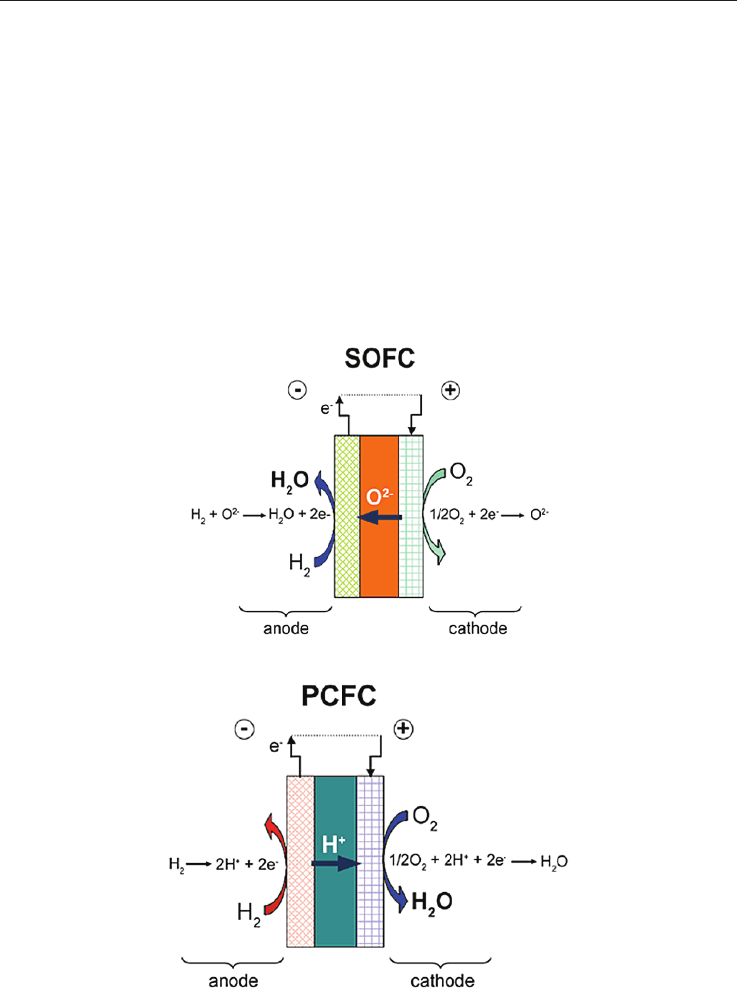
Solid Oxide Fuel Cells are promising power generating systems which are currently based
on anionic solid conductors (SOFC), mostly Yttria-Stabilized Zirconia (YSZ), or more
recently on protonic conductors (PCFC) in which the electrolyte may be an yttrium doped
barium cerate (BCY) or zirconate (BZY) (see Fig. 1 and 2). The operating temperature of
YSZ-based SOFC is usually high (> 900 °C) in order to reach the highest anionic conduction
performance. This presents significant advantages (chemical stability with CO and CO
2
,
direct CH
4
feeding, etc…), but also severe pitfalls (thermomechanical failure of components,
sophisticated glass seals, chemical instabilities during ageing and cycling…). These
difficulties can be significantly diminished if the operating temperature is reduced to 600
°C - 700 °C; but then the loss of conductivity associated with the temperature drop must be
compensated either by changing the electrolyte material (i.e. shifting to Ceria) or by
drastically diminishing the electrolyte thickness.
Fig. 1. SOFC, water at the anode side
Fig. 2. PCFC, water at the cathode side
PCFCs are quite credible alternatives, though at a much less mature state of development
than SOFC. Among all the perovskite based proton conductors, 10% Yttria-substituted
Barium cerate (BCY10) is widely studied for its high level of protonic conduction below
700 °C under hydrogen-and/or water-containing atmospheres (10
-2
S cm
-1
at 600 °C under
wet hydrogen). But this class of materials displays some particularities (high basicity, high
sensitivity to water and CO
2
, high refractarity, chemical decomposition at high temperature,
residual oxygen conduction under certain conditions…), which make them requiring still a
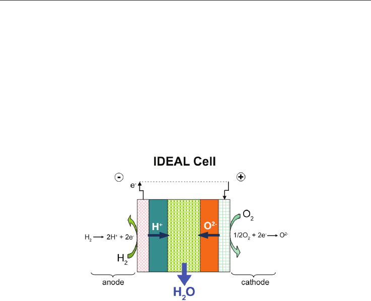
certain amount of basic research prior to development. An innovative design is under
scrutiny for a couple of years now (IDEAL-Cell); it consists of a mixed conducting cell that
will potentially eliminate all the problems associated with the presence of water at
electrodes in both SOFCs and PCFCs since the water is formed and evacuated from a porous
central membrane made of a composite of the two types of electrolytes (Fig.3)(see
www.ideal-cell-eu; Thorel et al, 2009a; Thorel et al, 2009b).
Fig. 3. IDEAL-Cell concept, water production in the central compartment
1.3. Designs and Fabrication Processes
The general geometries for these high temperature cells -at least SOFCs and PCFCs, IDEAL-
Cell being just at the proof of the concept step- are either planar or tubular, industrials
giving their own twist between these two basic designs. Though less tested on the long
term, planar designs provide a higher current density than tubular designs, between 0.50
and 1.5 W cm
-2
. The major brake to the development of high temperature fuel cells is the
cost of fabrication compared to the market requirements. Whatever the geometry, a single
cell is a complex quasi-2D multilayered structure made of different sophisticated materials
having different microstructures and functions. If one focuses on the planar geometry, many
processing routes can be envisioned, but the community considers only a limited number of
low cost shaping processes. They can be divided into 2 classes, i/ those that require the use
of a slurry (tape-casting, screen-printing, slip-coating, dip-coating…), and ii/ those in which
the powder is projected on a target (essentially plasma spraying related deposition
processes). Other excellent processes (PVD-CVD, SPS, hot-pressing…) are a priori too
expensive and difficult to scale-up, and therefore not competitive enough to meet with the
market constraints (i.e. US SECA program cost target = $400/kW by 2010). Plasma-spraying,
tape-casting and screen-printing have given first-rate results for fabrication of SOFCs [Hui et
al, 2007; Syed et al, 2006; Grosjean, 2004; Bitterlich et al, 2001;Xia et al, 2001). Surprisingly,
very few studies have been carried out so far on shaping PCFC via these processes (Costa et
Tape Casting Ceramics for high temperature Fuel Cell applications 51
1.2. High Temperature Fuel Cells context
Solid Oxide Fuel Cells are promising power generating systems which are currently based
on anionic solid conductors (SOFC), mostly Yttria-Stabilized Zirconia (YSZ), or more
recently on protonic conductors (PCFC) in which the electrolyte may be an yttrium doped
barium cerate (BCY) or zirconate (BZY) (see Fig. 1 and 2). The operating temperature of
YSZ-based SOFC is usually high (> 900 °C) in order to reach the highest anionic conduction
performance. This presents significant advantages (chemical stability with CO and CO
2
,
direct CH
4
feeding, etc…), but also severe pitfalls (thermomechanical failure of components,
sophisticated glass seals, chemical instabilities during ageing and cycling…). These
difficulties can be significantly diminished if the operating temperature is reduced to 600
°C - 700 °C; but then the loss of conductivity associated with the temperature drop must be
compensated either by changing the electrolyte material (i.e. shifting to Ceria) or by
drastically diminishing the electrolyte thickness.
Fig. 1. SOFC, water at the anode side
Fig. 2. PCFC, water at the cathode side
PCFCs are quite credible alternatives, though at a much less mature state of development
than SOFC. Among all the perovskite based proton conductors, 10% Yttria-substituted
Barium cerate (BCY10) is widely studied for its high level of protonic conduction below
700 °C under hydrogen-and/or water-containing atmospheres (10
-2
S cm
-1
at 600 °C under
wet hydrogen). But this class of materials displays some particularities (high basicity, high
sensitivity to water and CO
2
, high refractarity, chemical decomposition at high temperature,
residual oxygen conduction under certain conditions…), which make them requiring still a
certain amount of basic research prior to development. An innovative design is under
scrutiny for a couple of years now (IDEAL-Cell); it consists of a mixed conducting cell that
will potentially eliminate all the problems associated with the presence of water at
electrodes in both SOFCs and PCFCs since the water is formed and evacuated from a porous
central membrane made of a composite of the two types of electrolytes (Fig.3)(see
www.ideal-cell-eu; Thorel et al, 2009a; Thorel et al, 2009b).
Fig. 3. IDEAL-Cell concept, water production in the central compartment
1.3. Designs and Fabrication Processes
The general geometries for these high temperature cells -at least SOFCs and PCFCs, IDEAL-
Cell being just at the proof of the concept step- are either planar or tubular, industrials
giving their own twist between these two basic designs. Though less tested on the long
term, planar designs provide a higher current density than tubular designs, between 0.50
and 1.5 W cm
-2
. The major brake to the development of high temperature fuel cells is the
cost of fabrication compared to the market requirements. Whatever the geometry, a single
cell is a complex quasi-2D multilayered structure made of different sophisticated materials
having different microstructures and functions. If one focuses on the planar geometry, many
processing routes can be envisioned, but the community considers only a limited number of
low cost shaping processes. They can be divided into 2 classes, i/ those that require the use
of a slurry (tape-casting, screen-printing, slip-coating, dip-coating…), and ii/ those in which
the powder is projected on a target (essentially plasma spraying related deposition
processes). Other excellent processes (PVD-CVD, SPS, hot-pressing…) are a priori too
expensive and difficult to scale-up, and therefore not competitive enough to meet with the
market constraints (i.e. US SECA program cost target = $400/kW by 2010). Plasma-spraying,
tape-casting and screen-printing have given first-rate results for fabrication of SOFCs [Hui et
al, 2007; Syed et al, 2006; Grosjean, 2004; Bitterlich et al, 2001;Xia et al, 2001). Surprisingly,
very few studies have been carried out so far on shaping PCFC via these processes (Costa et

Ceramic Materials 52
al, 2009; Hafsaoui, 2009; Costa, 2009), which are all presently considered for shaping IDEAL-
Cell (Presto et al, 2009).
Ideally, a low-cost process that allows co-sintering the multilayer would be very profitable
in terms of fast development of SOFCs or PCFCs; but this is an extremely difficult problem
that aims at obtaining flat well bonded layers with appropriate densities and fine-tuned
microstructures, with no appearance of cracks, secondary phases, chemical reactivity,
unwanted allotropic transformations. Apart from processes derived from the plasma
deposition and if we focus on the more traditional ceramic processes, the previous
characteristics are all being governed ultimately only by three common parameters:
sintering temperature, duration of the treatment and atmosphere. Obviously, this very
limited number of levers that we can act on for-co-sintering can only trigger a differentiate
evolution of the layers only if the green layers have the potential to allow for it, that is to say
exhibit an appropriate geometry, composition, grain size distribution, initial density… The
green layers characteristics are in turn completely determined by the slurry composition and
powders morphology, the way the layers are superimposed and bonded, and how the
multilayer is being dried prior to sintering. In the present paper, that gathers results from
different projects (Grosjean, 2004; Costa et al, 2009; Hafsaoui, 2009; Costa, 2009), we will
focus on the problems encountered when one fabricates SOFC and PCFC by tape-casting
and co-sintering, and will detail some of the ideas suggested above.
2. Shaping by tape-casting
2.1. General considerations on tape-casting
Tape-casting is a low cost process particularly well-suited for the fabrication of thin (10 µm
up to 500 µm) flat components for high temperature fuel cell. It allows producing a wide
variety of controlled morphologies, from highly porous to fully dense microstructures, such
as electrodes and electrolytes. Green layers can be easily superimposed if one wants to co-
sinter the multilayer in a one-step operation. As seen in Fig. 4, the whole process gathers
consecutive steps: the first one and probably the most important is the fabrication of the
slurry with the powder under consideration, which is previously formulated, calcined and
eventually sieved to reach appropriate phase content, grain size distribution and
morphology.
Organic and/or inorganic additives, which role will be described below, are added to the
powder to form the slurry. The slurry is then mixed and grinded mostly by ball-milling to
ensure homogenization and destruction of agglomerates. Then the solution is de-aired
under primary vacuum depending on which level of porosity/density is desired at the end
of the process. The slurry is then ready for the casting of a green tape, which thickness is
governed by the height of the Doctor blade above the substrate (Fig. 5 and Fig. 6). The ratio
between the green and the sintered sample thicknesses depends on the properties of the
slurry and on the degree of freedom of the system when the layers shrink during drying and
during sintering, which in turn depends on numerous intrinsic parameters (i.e. those taken
into account in a dilatometry curve, such as powder nature, size, composition and
formulation of the slurry, temperature and duration of sintering…), but also on extrinsic
parameters linked to the nature of the substrates for drying or sintering, that may lead to
friction and wear inhibiting radial shrinkage and increasing then the level of
vertical/longitudinal shrinkage.
This may even be more effective if a light weight is deposited on top of the samples to
maintain its flatness. The different wet layers can then be cast on top of the others via
dedicated technical systems (i.e. series of Mylar masks) if the solvent is organic; if the
solvent is water, then the layers must go through a gel-forming step prior to
superimposition since otherwise they do not exhibit any mechanical strength. Technical
adjustments can be carried out between these two solutions, but it is important to note that a
good final bonding between two layers requires that at least one layer is wet. Drying single
layers or multilayers is also a prime importance step. Any geometric deformation or defect
occurring during the drying process will only worsen during sintering. It is therefore
essential that the flatness be maintained, depending on how isotropic the mechanism of
humidity withdrawal is, above, below and along the radius of the sample. If one uses a
dense substrate, then humidity cannot escape from the bottom and the dried sample is
usually warped with strong deformation in the z+ direction, along with edge sinusoidal
deformation. Sandwiching the sample between two dense substrates does not usually help
and ends up with extensive cracking. We have had excellent results when sandwiching the
layers or multilayers between two light honeycomb Mullite substrates left at 70 °C (Fig. 7).
Fig. 4. Flowchart for organic or aqueous tape-casting and co-sintering of multilayers