Wood J. Object-Oriented Programming with ABAP Objects
Подождите немного. Документ загружается.


7 | Component-Based Design Concepts
You should design your package interfaces using the least privilege principle
described in Chapter 5, Inheritance. In other words, only add the development
objects that outside packages will need to carry out their work. This way, you can
potentially use the use access functionality described in Section 7.2.5, Creating
Use Accesses, to ensure that no one can use development objects hidden within a
package. This gives you the flexibility to change or remove development objects
within a package without having to worry about what kind of problems it might
cause to other programs.
7.2.5 Creating Use Accesses
Frequently, development objects in one package depend on development objects
defined in another package. Prior to the release of the package concept, depen-
dencies between development objects could be created at whim by developers
without any restrictions whatsoever. From a logistics perspective, this was highly
problematic because it was next to impossible to prevent developers from using
development objects that they shouldn't be using for one reason or another.
Here, for example, developers might start using a "helper" class or function that
was not intended to be used publicly. Once this dependency exists, it is difficult
to modify (and remove) this helper module without causing widespread prob-
lems in the system.
This logistics problem can be solved by creating explicit use accesses between
packages. Technically, these dependency checks are only enforced whenever cer-
tain system settings are turned on (more on this in Section 7.2.6, Performing
Package Checks). A use access formally declares a client (or user) package's inten-
tions to use development objects defined in the package interface of
a
server (or
provider) package. To define a use access, follow these steps:
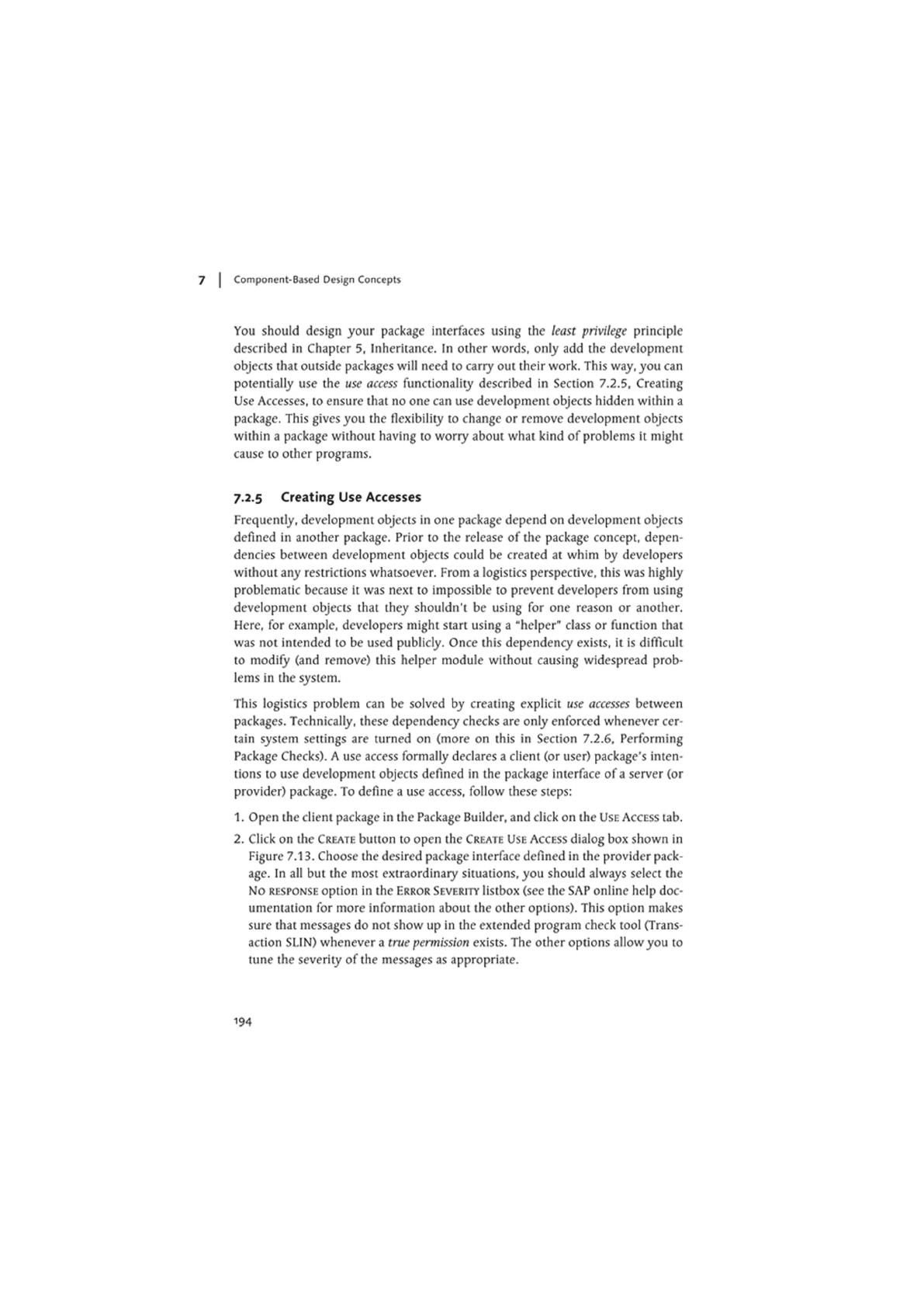
1. Open the client package in the Package Builder, and click on the USE ACCESS tab.
2. Click on the CREATE button to open the CREATE USE ACCESS dialog box shown in
Figure 7.13. Choose the desired package interface defined in the provider pack-
age. In all but the most extraordinaiy situations, you should always select the
No RESPONSE option in the ERROR SEVERITY listbox (see the SAP online help doc-
umentation for more information about the other options). This option makes
sure that messages do not show up in the extended program check tool (Trans-
action SLIN) whenever a true permission exists. The other options allow you to
tune the severity of the messages as appropriate.
194

The Package Concept
Px«»9»
tnmtitx PxUgot
mtluflt-3
Haorttiy
C>m« r D«t»»
Patina irifrfy.o
|&Pxk»»»Omia«f ct»»wu»>Atc«»«
_B/
P»:og«
iniwiac*
EnwSwiV
|B
No pont*
imcrmio&n
kVamtng
Eno«
ObH
*
Figure 7-13 Creating Use Accesses in Packages
3. Click the APPLY VALUES button to create the use access. Also remember to click
the SAVE button in the Package Builder to save the changes to the client pack-
age.
Even if your development organization is not ready for component-based soft-
ware development, it is still a good idea to create explicit use accesses so thatyou
can keep track of the dependencies that exist between various packages. To fully
appreciate the value of this practice, let's consider an example where knowledge
of these dependencies might come in handy.
Let's imagine that an organization is looking to expand its current SAP footprint
to include other products in the SAP Business Suite such as SAP CRM or SAP SRM.
Because all of these products run on the SAP NctWeaver Application Server, it is
quite possible that there might be common development objects thatyou want to
share across the landscape. However, without defined use accesses, it may be
veiy difficult to transport these common objects because it is next to impossible
to physically trace all of the possible dependencies that may exist between the
individual objects. In this
case,
just a little bit of preparation up-front can make all
the difference in avoiding many unpleasant logistical problems down the road.
7.2.6 Performing Package Checks
The creation of use accesses between packages requires some additional disci-
pline in the software development process. After all, it is much easier to simply
start using a development object without having to register its use beforehand. To
195

7 | Component-Based Design Concepts
save developers from themselves, SAP has provided a package check tool that is
integrated in the extended syntax check feature of the ABAP Workbench.
The package check tool can be used to assist you in finding places in your code
where you are using development objects in other packages without first declar-
ing a use access. By default, the package check tool is switched off in customer
systems, so you will need to work with your local Basis administration staff to
turn this setting on (see SAP Note 648898 for details on how to configure this set-
ting in your system). The SAP online help documentation walks through several
scenarios that demonstrate how the package check works based on various sys-
tem setting configurations.
7.2.7 Package Design Concepts
There are no hard-and-fast rules for designing packages and package interfaces.
For example, there is no law that states you must use structure or main packages
to organize your development objects; you can simply organize your develop-
ment objects into sub-packages. In fact, many projects simply create one big sub-
package to store eveiything. Conversely, it is also possible to overdesign package
hierarchies to the point that they are too granular to be of
much
use.
In his book UML Distilled (Addison-Wesley, 2004), Martin Fowler describes three
basic principles thatyou can use to help design your package architectures
4
:
• The Common Closure Principle says that development objects within the same
package should be changed for the same reasons.
• The Common Reuse Principle suggests that development objects within a pack-
age should all be reused together.
• The Static Dependencies Principle advises you to consider how stable your pack-
age is if there are many dependencies flowing into it.
For example, if 10 packages are dependent on a single package, it is important
for the interface of that package to be stable to avoid widespread rippling
affects whenever
a
change occurs. Here, it is often useful to define the interface
of that package in terms of interfaces and abstract classes because they provide
the flexibility that is needed to adapt to change.
4 Mr. Fowler credits Robert Cecil Martin's The Principles, Patterns, and Practices of Agile Software
Development (Prcnticc-Hall. 2003) when describing these principles.
196

UML Tutorial: Package Diagrams
73
The application of these principles to your package designs should help keep you
on track. Also, keep in mind thatyou are not locked into a particular design ifyou
eventually find that it is not working for your project. Package relationships, just
like classes, sometimes require refactoring. Fortunately, the ABAP Workbench
makes it easy for you to reassign development objects to other packages.
7.3 UML Tutorial: Package Diagrams
The component design process can become quite involved, being heavily influ-
enced by the subjective whims of developers that often have conflicting design
goals. Typically, this process evolves over several iterations that gradually reshape
the model to reflect the system that is being implemented. The UML supports the
documentation of this design process with the package diagram. A package dia-
gram allows you to group related classes and interfaces (and other development
objects) into higher-level units called packages.
Note that the overlap between the term "package" in the UML and the ABAP
packages you learned about in Section 7.2, The Package Concept, is purely coin-
cidental. A UML package is a logical concept that could be implemented in many
different ways by various programming languages. However,
as
you will see, the
ABAP package concept aligns veiy closely with the UML package construct.
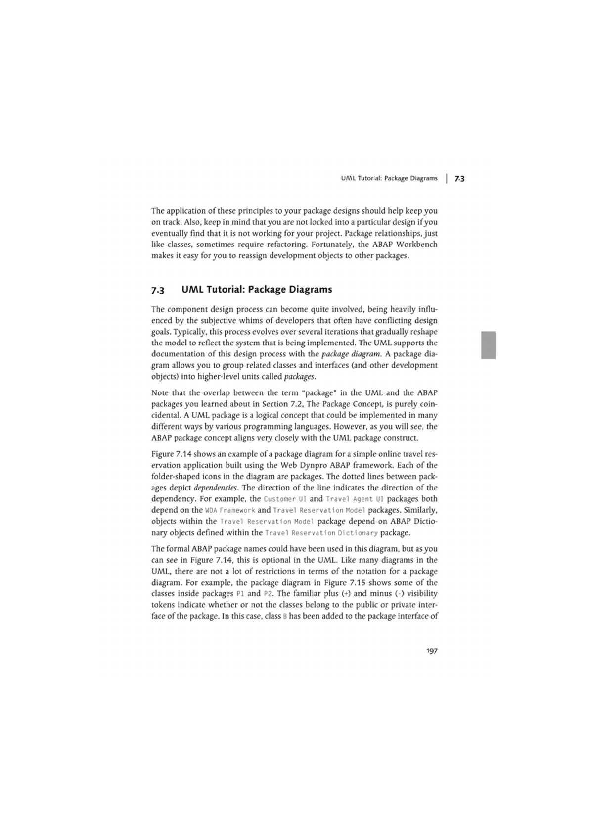
Figure 7.14 shows an example of
a
package diagram for a simple online travel res-
ervation application built using the Web Dynpro ABAP framework. Each of the
folder-shaped icons in the diagram are packages. The dotted lines between pack-
ages depict dependencies. The direction of the line indicates the direction of the
dependency. For example, the Customer UI and Travel Agent ui packages both
depend on the
WOA
Framework and Travel Reservation Model packages. Similarly,
objects within the Travel Reservation Model package depend on ABAP Dictio-
naiy objects defined within the Travel Reservation Dictionary package.
The formal ABAP package names could have been used in this diagram, but
as
you
can see in Figure 7.14, this is optional in the UML. Like many diagrams in the
UML, there are not a lot of restrictions in terms of the notation for a package
diagram. For example, the package diagram in Figure 7.15 shows some of the
classes inside packages PI and P2. The familiar plus (+) and minus ( ) visibility
tokens indicate whether or not the classes belong to the public or private inter-
face of the package. In this case, class
B
has been added to the package interface of
197

7 | Component-Based Design Concepts
package
PI.
The dependency line drawn between package P2 and PI could be used
to represent a use access (i.e.. class C is using class B, etc.).
Figure 7-14 Package Diagram for Web Dynpro Application
P1
-A +B
-C
Figure 7.15 Including Objects in a Package Diagram
198

Summary |
Packagc diagrams are veiy useful in illustrating a system design in terms of its
constituent components. If you find that the package diagram for your system
looks like a plate of spaghetti, it is likely that your packages are not well encapsu-
lated. Consequently, updating your package diagrams periodically is a good way
to gauge the effectiveness ofyour component designs over time.
7.4 Summary
In this chapter, we looked at how to perform component-based software devel-
opment in ABAP. As you learned, component-based software development in
ABAP is predicated upon the package concept, which goes beyond the visibility
concepts of classes to encapsulate development objects together inside of a logical
software unit.
In the next chapter, we will explore the ABAP class-based exception handling
concept, which enables you to cleanly implement logic to gracefully recover from
exception situations that can occur within programs.
199


Software programs operate in an environment based on rules. However,
as the saying goes, there's an exception to every rule. In this chapter, we
will explore ways to deal with exception situations that can arise in ABAP
Objects programs.
8 Error Handling with Exceptions
No matter how hard we may try to improve the quality of our code, there is sim-
ply no way to avoid every type of error that could occur during the execution of
an application. In fact, some errors are accidentally introduced by programmers
trying too hard to make their applications error-proof Here, for instance, the
error-handling logic obscures the main purpose of the program flow, making the
code harder to understand and maintain, and thus, more susceptible to errors.
Error-handling logic is a cross-cutting concern that becomes tangled within the
normal flow of the core application logic. Ideally, you want to de-tangle error-
handling logic from the main program flow so that these two orthogonal con-
cerns can be managed separately. In this chapter, you will learn how to apply the
ABAP class-based exception-handling concept to achieve this kind of separation of
concerns.
8.1 Lessons Learned from Prior Approaches
Prior to Release 6.10 of the SAP Web Application Server, there was no compre-
hensive strategy for dealing with exceptions within the ABAP Objects language.
Consequently, developers were forced to improvise, weaving custom exception-
handling code into their normal program flow. The code snippet in Listing 8.1
shows an example of some error-handling logic that has been added to a program
that is calling a series of subroutines to perform various tasks.
OATA: lv_retcode TYPE sy-subrc.
PERFORM sub_routinel CHANGING lv_retcode.
201

8 | Error Handling with Exceptions
IF lv_retcode NE 0.
"Error Handling Logic
ENDIF.
PERFORM sub_routine2 CHANGING lv_retcode.
CASE lv_retcode.
WHEN 0.
WHEN
1.
WHEN 2.
WHEN OTHERS.
ENDIF.
PERFORM sub_routine3 CHANGING 1v_retcode.
IF lv_retcode NE 0.
"Redundant Error Handling Logic???
ENDIF.
Listing 8.1 Example of a Manual Exception-Handling Approach
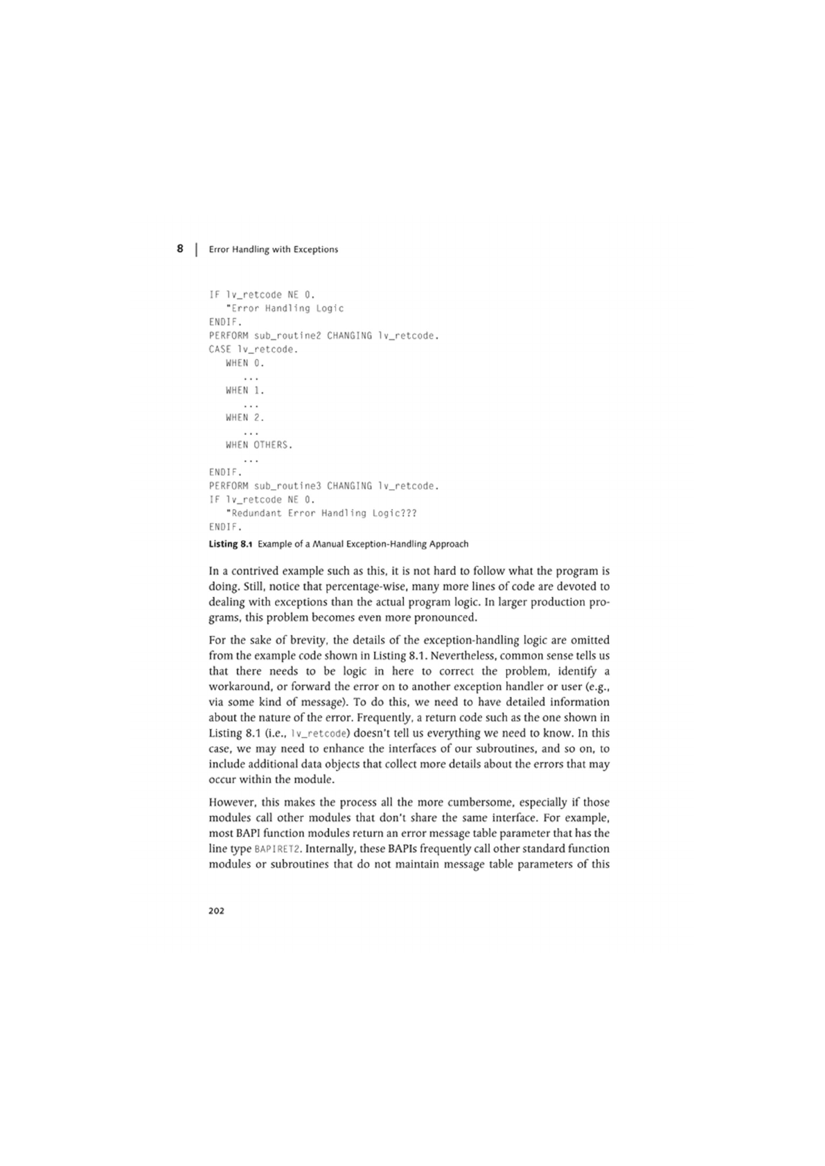
In a contrived example such as this, it is not hard to follow what the program is
doing. Still, notice that percentage-wise, many more lines of code are devoted to
dealing with exceptions than the actual program logic. In larger production pro-
grams, this problem becomes even more pronounced.
For the sake of brevity, the details of the exception-handling logic are omitted
from the example code shown in Listing 8.1. Nevertheless, common sense tells us
that there needs to be logic in here to correct the problem, identify a
workaround, or forward the error on to another exception handler or user (e.g.,
via some kind of message). To do this, we need to have detailed information
about the nature of the error. Frequently, a return code such as the one shown in
Listing 8.1 (i.e., lv_retcode) doesn't tell us eveiything we need to know. In this
case, we may need to enhance the interfaces of our subroutines, and so on, to
include additional data objects that collect more details about the errors that may
occur within the module.
However, this makes the process all the more cumbersome, especially if those
modules call other modules that don't share the same interface. For example,
most BAPI function modules return an error message table parameter that has the
line type
BAP IRET2.
Internally, these BAPIs frequently call other standard function
modules or subroutines that do not maintain message table parameters of this
202

The Class-Based Exception Handling Concept
type. Consequently, additional code has to be written in the BAPI function to
translate between the various message table types. In Section 8.5, Creating Excep-
tion Classes, you will see how to develop exception classes that encapsulate these
details more efficiently.
Another problem with ad-hoc exception handling strategies is the fact that it can
be very difficult to identify the types of errors that can occur within a given mod-
ule without having to first dig into the code. For instance, in Listing 8.1, how do
you determine the potential problems thatyou need to account for when you call
sub_routinel, and so on? From a design perspective, you want the interface of
your modules to be more explicit about the types of errors that can occur within
them.
After all, exceptions are part of the API contract for a module, too. To some
degree, certain previous concepts provide support for this requirement. For
example, you can create named exceptions for function modules using the EXCEP
HONS addition. However, these exceptions arc essentially static error codes that
have been assigned some semantic meaning inside the function module. The
meaning of these exceptions tends to become obscured outside of the scope of
the function module, especially when new exceptions are added into the mix.
Recognizing this, SAP decided to implement a new class-based concept for deal-
ing with exceptions that could be used consistently in all ABAP contexts (i.e.. pro-
grams, processing blocks, etc.). You will learn more about this concept in Section
8.2, The Class-Based Exception Handling Concept.
8.2 The Class-Based Exception Handling Concept
As the name suggests, the class-based exception handling concept uses special
classes called exception classes to encapsulate exception situations that can occur
within a program. These classes are integrated into a framework that makes it eas-
ier for you to separate the exception-handling aspects of
a
program from the core
functional aspects of the program. This framework is orchestrated by the TRY con-
trol structure whose form is shown in Listing 8.2.
TRY.
"Application coding block
CATCH cx_exception_type
203
