Tong W. Wind Power Generation and Wind Turbine Design
Подождите немного. Документ загружается.

Wind Energy Storage Technologies 665
system fl exibility is maximised. An ideal option to achieve this is by integrating
the three primary sectors within any energy system: the electricity, heat and
transport sectors. HESS, TESS and EVs provide unique opportunities to inte-
grate these three sectors and hence increase the renewable energy penetrations
feasible. As a result it is diffi cult to compare HESS, TESS and EVs to the other
energy storage technologies directly as energy storage is only part of the purpose
of those systems.
4.1 Pumped-hydroelectric energy storage
PHES is the most mature and largest capacity storage technique available. A pump
and turbine have been combined in a single device optimised for this purpose.
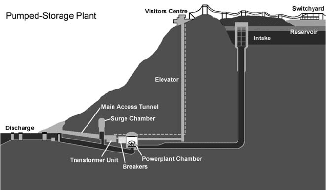
PHES consists of two large reservoirs located at different elevations and a number
of pump turbine units (see Fig. 1 ). During off-peak electrical demand, water is
pumped from the lower reservoir to the higher reservoir where it is stored until it
is needed. When required (i.e. during peak electrical production) the water in the
upper reservoir is released through the turbines, which are connected to generators
that produce electricity. Therefore, during production a PHES facility operates
similarly to a conventional hydroelectric system.
The effi ciency of operational pumped storage facilities is in the region of 50–85%
with more modern units at the upper end. However, variable speed machines are
now being used to improve this. The effi ciency is limited by the effi ciency of the
pump/turbine unit used in the facilities [ 2 ]. Until recently, PHES units have always
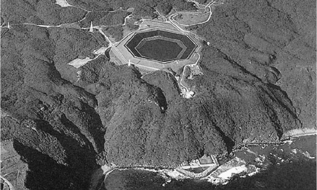
used fresh water as the storage medium. However, in 1999 a PHES facility using
seawater as the storage medium was constructed [ 6 ] (see Fig. 2 ); corrosion was
Figure 1: Pumped-hydroelectric energy storage layout [ 5 ].
666 Wind Power Generation and Wind Turbine Design
prevented by using paint and cathodic protection. A typical PHES facility has
300 m of hydraulic head (the vertical distance between the upper and lower reser-
voir). The power capacity (kW) is a function of the fl ow rate and the hydraulic head,
while the energy stored (kWh) is a function of the reservoir volume and hydrau-
lic head. To calculate the mass power output of a PHES facility, the following
relationship can be used [ 7 ]:
C
P gQHnr=
(1)
where P
C
is the power capacity in W, r the mass density of water in kg/m
3
, g the
acceleration due to gravity in m/s
2
, Q the discharge through the turbines in m
3
/s,
H the effective head in m and n is the effi ciency.
Also, the storage capacity of the PHES may be evaluated with the following
equation [ 8 ]:
C
S V gHnr=
( 2)
where S
C
is the storage capacity in megawatt-hours (MWh) and V is the volume
of water that is drained and fi lled each day in m
3
. It is evident that the power and
storage capacities are both dependent on the head and the volume of the reservoirs.
However, facilities should be designed with the greatest hydraulic head possible
rather than largest upper reservoir possible. It is much cheaper to construct a facil-
ity with a large hydraulic head and small reservoirs, than to construct a facility
of equal capacity with a small hydraulic head and large reservoirs because: less
material needs to be removed to create the reservoirs required; smaller piping is
necessary, hence, smaller boreholes during drilling; the pump turbine is physically
smaller. Currently, there is over 90 GW in more than 240 PHES facilities in the
Figure 2: Pumped-hydroelectric storage facility using seawater at Okinawa,
Japan [ 6 ].
Wind Energy Storage Technologies 667
world – roughly 3% of the world’s global generating capacity. Individual facilities
can store up to 15 GWh of electrical energy from in plant with power ratings from
30 to 4000 MW [ 2 ].
4.1.1 Applications of PHES
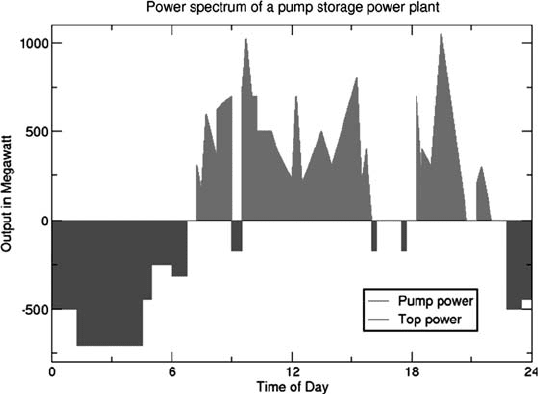
Similar to large storage capacities, PHES also has a fast reaction time, making
it ideal for load levelling applications, where the plant can vary its effective load
on the system from the full name plate rating in the positive direction (pumping)
to the full name plate rating in the negative direction (generating) (see Fig. 3 ).
Facilities can have a reaction time as short as 10 min or less from complete shut-
down (or from full reversal of operation) to full power [ 3 ]. In addition, if kept on
standby, full power can even be reached within 10–30 s.
Also, with the recent introduction of variable speed machines, PHES systems can
now be used for frequency regulation in both pumping and generation modes (this
has always been available in generating mode). This allows PHES units to absorb
power in a more cost-effective manner that not only makes the facility more useful,
but also improves the effi ciency by approximately 3% [ 3 ] and extends the life of the
facility. PHES can also be used for peak generation and black starts (start generating
without access to a main frequency set by other units on the grid) due to its large
power capacity and suffi cient discharge time. Finally, PHES provides a load for
base-load generating facilities during off-peak production, hence, cycling these units
can be avoided which improves their lifetime as well as their effi ciency.
4.1.2 Cost of PHES
Cost ranges from $600/kW [ 2 ] to upwards of $2000/kW [ 3 ], depending on a number
of factors such as size, location and connection to the power grid.
Figure 3: Output from a pumped-hydroelectric storage facility [ 5 ].
668 Wind Power Generation and Wind Turbine Design
4.1.3 Disadvantages of PHES
A major disadvantage of PHES facility is its dependence on specifi c geological
formations, because two large reservoirs with a suffi cient hydraulic head between
them must be located within close proximity to build a PHES system. As well as
being rare, these geological formations normally exist in remote locations such
as mountains, where construction is diffi cult and the power grid is not present,
although large wind farm sites may provide a useful modern alternative. Finally,
in order to make a PHES plant viable it must be constructed on a large scale.
Although the cost per kWh of storage is relatively economical in comparison to
other techniques, this results in a very high initial construction cost for the facility,
therefore deterring investment in PHES, e.g. Bath County storage facility in the
United States which has a power capacity of 2100 MW cost $1.7 billion in 1985.
4.1.4 Future of PHES
Currently, a lot of work is being carried out to upgrade old PHES facilities with
new equipment such as variable speed devices which can increase capacity by
15–20% and effi ciency by 5–10%. This is more desirable as energy storage capac-
ity can be added without the high initial construction costs. Prospects of building
new facilities are limited due to the “high development costs, long lead times and
design limitations” [ 3 ]. However, a new concept that is showing a lot of theoretical
potential is UPHES, discussed in the next section.
4.2 Underground pumped-hydroelectric energy storage
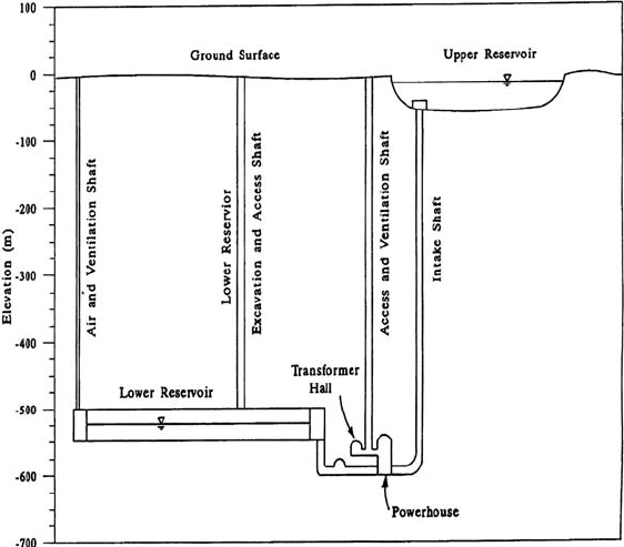
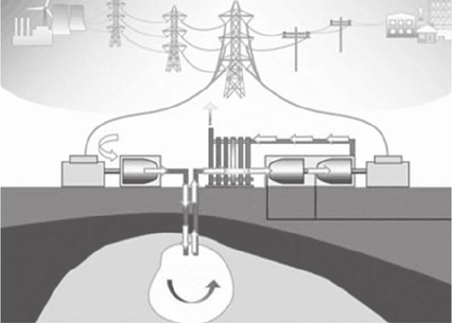
An UPHES facility has the same operating principle as PHES system: two res-
ervoirs with a large hydraulic head between them. The only major difference
between the two designs is the locations of their respective reservoirs. In conven-
tional PHES, suitable geological formations must be identifi ed to build the facil-
ity, as discussed earlier (see Section 5.1). However, UPHES facilities have been
designed with the upper reservoir at ground level and the lower reservoir deep
below the earth’s surface. The depth depends on the amount of hydraulic head
required for the specifi c application (see Fig. 4 ).
4.2.1 Applications of UPHES
UPHES can provide the same services as PHES: load levelling, frequency regu-
lation, and peak generation. However, as UPHES does not need to be built at a
suitable geological formation, it can be constructed anywhere with an area large
enough for the upper reservoir. Consequently, it can be placed in ideal locations to
function with wind farms, the power grid, specifi c areas of electrical irregularities,
etc. The fl exibility of UPHES makes it a more attractive option for energy storage
than conventional PHES, but its technical immaturity needs to be addressed.
4.2.2 Cost of UPHES
The capital cost of UPHES is the deciding factor for its future. As it operates in the
same way as PHES, it is a very reliable and cost-effective storage technique with
Wind Energy Storage Technologies 669
low maintenance costs. However, depending on the large capital costs involved,
UPHES might not be a viable option as other technologies begin to develop larger
storage capacities, e.g. fl ow batteries. Currently, no costs have been identifi ed for
UPHES, primarily due to the lack of facilities constructed. A number of possible
cost-saving ideas have been put forward such as using old mines for the lower
reservoir of the facility [ 7 , 9 ]. Also, if something valuable can be removed to make
the lower reservoir, it can be sold to make back some of the cost.
4.2.3 Disadvantages of UPHES
UPHES incorporates the same disadvantages as PHES (large-scale required, high
capital costs, etc.), with one major exception. As stated previously (see Section 5.1),
the most signifi cant problem with PHES is its geological dependence. As the
lower reservoir is obtained by drilling into the ground and the upper reservoir is at
ground level, UPHES does not have such stringent geological dependences. The
major disadvantage for UPHES is its commercial youth. To date there is very few,
if any, UPHES facilities in operation. Therefore, it is very diffi cult to analyse and
to trust the performance of this technology.
4.2.4 Future of UPHES
UPHES has a very bright future if cost-effective excavation techniques can
be identifi ed for its construction. Its relatively large-scale storage capacities,
Figure 4: Proposed underground pumped-hydroelectric storage facility layout [ 7 ].
670 Wind Power Generation and Wind Turbine Design
combined with its location independence, provide a storage technique with unique
characteristics. However, as well as cost, a number of areas need to be investigated
further in this area such as its design, power and storage capacities and environ-
mental impact to prove it is a viable option.
4.3 Compressed air energy storage
A CAES facility consists of a power train motor that drives a compressor (to com-
press the air into the cavern), high pressure turbine (HPT), a low pressure turbine
(LPT), and a generator (see Fig. 5 ).
In conventional gas turbines (GTs), 66% of the gas used is required to compress
the air at the time of generation. Therefore, CAES pre-compresses the air using
off-peak electrical power which is taken from the grid to drive a motor (rather than
using gas from the GT plant) and stores it in large storage reservoirs. When the GT
is producing electricity during peak hours, the compressed air is released from the
storage facility and used in the GT cycle. As a result, instead of using expensive
gas to compress the air, cheaper off-peak base-load electricity is used. However,
when the air is released from the cavern it must be mixed with a small amount of
gas before entering the turbine. If there was no gas added, the temperature and
pressure of the air would be problematic. If the pressure using air alone was high
enough to achieve a signifi cant power output, the temperature of the air would be
far too low for the materials and connections to tolerate [ 1 ]. The amount of gas
Fuel (Natural Gas)
Motor
Compressor
Recuperator
HPT
Generator
LPT
Cavern
Waste Heat
Exhaust
Air
Compressed
Air
Salt Dome
Figure 5: Compressed air energy storage facility [ 10 ].
Wind Energy Storage Technologies 671
required is so small that a GT working simultaneously with CAES can produce
three times more electricity than a GT operating on its own, using the same amount
of natural gas.
The reservoir can be man-made but this is expensive so CAES locations are
usually decided by identifying natural geological formations that suit these facili-
ties. These include salt-caverns, hard-rock caverns, depleted gas fi elds or an aqui-
fer. Salt-caverns can be designed to suit specifi c requirements. Fresh water is
pumped into the cavern and left until the salt dissolves and saturates the fresh
water. The water is then returned to the surface and the process is repeated until the
required volume cavern is created. This process is expensive and can take up to
2 years. The costs associated with hard-rock caverns are likely to be more than
50% higher. Finally, aquifers cannot store the air at high pressures and therefore
have a relatively lower energy capacity.
CAES uses both electrical energy and natural gas so its effi ciency is diffi cult to
predict. It is estimated that the effi ciency of the entire cycle is in the region of 64%
[ 11 ] to 75% [ 3 ]. Typical plant capacities for CAES are in the region of 50–300 MW.
The life of these facilities is proving to be far longer than existing GTs and the
charge/discharge ratio is dependent on the size of the compressor used, as well as
the size and pressure of the reservoir.
4.3.1 Applications of CAES
CAES is the only very large-scale storage technique other than PHES. CAES
has a fast reaction time with plants usually able to go from 0 to 100% in less
than 10 min, 10 to 100% in approximately 4 min and 50 to 100% in less than
15 s [ 2 ]. As a result, it is ideal for acting as a large sink for bulk energy supply
and demand and also, it is able to undertake frequent start-ups and shutdowns.
Furthermore, traditional GT suffer a 10% effi ciency reduction from a 5°C rise
in ambient temperatures due to a reduction in the air density. CAES use com-
pressed air so they do not suffer from this effect. Also, traditional GTs suffer
from excessive heat when operating on partial load, while CAES facilities do
not. These fl exibilities mean that CAES can be used for ancillary services such
as frequency regulation, load following, and voltage control [ 3 ]. As a result,
CAES has become a serious contender in the wind power energy storage mar-
ket. A number of possibilities are being considered such as integrating a CAES
facility with a number of wind farms within the same region. The excess off-
peak power from these wind farms could be used to compress air for a CAES
facility. Iowa Association of Municipal Utilities is currently planning a project
of this nature [ 12 ].
4.3.2 Cost of CAES
The cost of CAES facilities are $425/kW [ 2 ] to $450/kW [ 3 ]. Maintenance is esti-
mated between $3/kWh [ 13 ] and $10/kWh [ 14 ]. Costs are largely dependent on
the reservoir construction. Overall, CAES facilities expect to have costs similar to
or greater than conventional GT facilities. However, the energy cost is much lower
for CAES systems.
672 Wind Power Generation and Wind Turbine Design
4.3.3 Disadvantages of CAES
The major disadvantage of CAES facilities is their dependence on geographical
location. It is diffi cult to identify underground reservoirs where a power plant can
be constructed, is close to the electric grid, is able to retain compressed air and is
large enough for the specifi c application. As a result, capital costs are generally
very high for CAES systems. Also, CAES still uses a fossil fuel (gas) to generate
electricity. Consequently, the emissions and safety regulations are similar to con-
ventional GTs. Finally, only two CAES facilities currently exist, meaning it is still
a technology of potential not experience.
4.3.4 Future of CAES
Reservoir developments are expected in the near future due to the increased use
of natural gas storage facilities. The US and Europe are more likely to investigate
this technology further as they possess acceptable geology for an underground res-
ervoir (specifi cally salt domes). Due to the limited operational experience, CAES
has been considered too risky by many utilities [ 14 ].
A number of CAES storage facilities have been planned for the future including:
25 MW CAES research facility with aquifer reservoir in Italy •
3 • × 100 MW CAES plant in Israel
Norton Energy Storage LLC in America is planning a CAES with a limestone •
mine acting as the reservoir. The fi rst of four phases is expected to produce
between 200 and 480 MW at a cost of $50 to $480 million. The fi nal plant out-
put is planned to be 2500 MW.
Finally, proposals have also been put forward for a number of similar technologies
such as micro-CAES and thermal and compressed air storage (TACAS). However,
both are in the early stages of development and their future impact is not decisive.
Although Joe Pinkerton, CEO of Active Power , declared that TACAS “is the fi rst
true minute-for-minute alternative to batteries for UPS industry” [ 3 ].
4.4 Battery energy storage
There are three important types of large-scale BES. These are: lead-acid (LA);
nickel-cadmium (NiCd); sodium-sulphur (NaS). These operate in the same way
as conventional batteries, except on a large scale, i.e. two electrodes are immersed
in an electrolyte, which allows a chemical reaction to take place so current can be
produced when required.
4.4.1 LA battery
This is the most common energy storage device in use at present. Its success is due
to its maturity (research has been ongoing for an estimated 140 years), relatively
low cost, long lifespan, fast response, and low self-discharge rate. These batteries
are can be used for both short-term applications (seconds) and long-term applica-
tions (up to 8 h). There are two types of LA batteries; fl ooded lead-acid (FLA) and
Wind Energy Storage Technologies 673
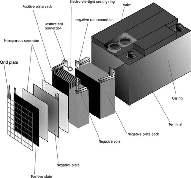
valve-regulated lead-acid (VRLA). FLA batteries are made up of two electrodes
that are constructed using lead plates which are immersed in a mixture of water
(65%) and sulphuric acid (35%) (see Fig. 6 ). VRLA batteries have the same oper-
ating principle as FLA batteries, but they are sealed with a pressure-regulating
valve. This eliminates air from entering the cells and also prevents venting of the
hydrogen. VRLA batteries have lower maintenance costs, weigh less and occupy
less space. However, these advantages are coupled with higher initial costs and
shorter lifetime.
Both the power and energy capacities of LA batteries are based on the size and
geometry of the electrodes. The power capacity can be increased by increasing the
surface area for each electrode, which means greater quantities of thinner electrode
plates in the battery. However, to increase the storage capacity of the battery, the
mass of each electrode must be increased, which means fewer and thicker plates.
Consequently, a compromise must be met for each application. LA batteries can
respond within milliseconds at full power. The average DC–DC effi ciency of a LA
battery is 75–85% during normal operation, with a life of approximately 5 years or
250–1000 charge/discharge cycles, depending on the depth of discharge [ 3 ].
Figure 6: Lead acid battery [ 15 ].

674 Wind Power Generation and Wind Turbine Design
4.4.1.1 Applications of LA battery
FLA batteries have two primary applications [ 3 ]:
Starting and ignition, short bursts of strong power e.g. car engine batteries 1.
Deep cycle, low steady power over a long time 2.
VRLA batteries are very popular for backup power, standby power supplies in
telecommunications and also for UPS systems. A number of LA storage facilities
are in operation today as can be seen in Table 1 .
4.4.1.2 Cost of LA battery
Costs for LA battery technology have been stated as $200/kW to $300/kW [ 2 ], but
also in the region of $580/kW [ 3 ]. Looking at Table 1 , the cost variation is evident.
4.4.1.3 Disadvantages of LA battery
LA batteries are extremely sensitive to their environments. The typical operating
temperature for a LA battery is roughly 27°C, but a change in temperature of
5°C or more can cut the life of the battery by 50%. However, if the DoD exceeds
this, the cycle life of the battery will also be reduced. Finally, a typical charge-
to-discharge ratio of a LA battery is 5:1. At faster rates of charge, the cell will
be damaged.
Table 1: Largest LA and VRLA batteries installed worldwide [ 2 ].
Plant
Year of
installation
Rated
Energy
(MWh)
Rate
Power
(MW)
Battery system
alone
Total cost of the
storage system
*
Cost in
$1995
($/kWh)
Cost in
$1995
($/kWh)
Cost in
$1995
($/kW)
Cost in
$1995
($/kW)
CHINO
California
1988 40 10 201 805 456 1823
HELCO
Hawaii
(VRLA)
1993 15 10 304 456 777 1166
PREPA
Puerto Rico
1994 14 20 341 239 1574 1102
BEWAG
Germany
1986 8.5 8.5 707 707 n/a n/a
VERNON
California
(VRLA)
1995 4.5 3 305 458 944 1416
*
Includes power conditioning system and balance-of-payment.
