Tong W. Wind Power Generation and Wind Turbine Design
Подождите немного. Документ загружается.

Design and Development of Small Wind Turbines 265
supply (gas, steam) is then cut off via an independent overspeed control mecha-
nism – a critical function since the overspeed condition can result in the destruction
of the turbine. In the case of wind turbines, the energy supply (the wind) cannot be
stopped, and so other means of overspeed control must be used. (It is interesting to
note that, just as in the case of turbines in conventional power stations, the primary
wind turbine speed control mechanism is the generator. Emergency overspeed
control only comes into play, e.g. when the generator fails.)
The obvious way to prevent wind turbine rotor overspeed is to pitch the blades,
and this is universally done on large wind turbines. It is possible to pitch the blades
either way (toward “feather” or toward “stall”), and there is more than one small
wind turbine using the pitch-to-stall approach for overspeed control (large wind
turbines use pitch-to-feather, pitching the blades through about 90°). However
only a few degrees of pitch variation in the other direction are required to achieve
a stall condition, and this can be done e.g. through a hub hinge or through pitch
weights mounted on a torsionally fl exible blade. While both of these pitch-to-stall
approaches are used in small wind turbines, neither approach is common.
The most common approach on small upwind turbines, as mentioned above, is
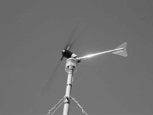
the furling tail. Figure 11 shows a turbine with the furling tail actuated. The main
features of a typical furling tail system are fi rstly the rotor has its centerline offset
from the centerline of the tower, and secondly it has a hinged tail (capable of furl-
ing in one direction but not the other). At times of excessive rotor thrust (as occurs
during overspeed), the thrust force causes the rotor to yaw “around the tower” and
the tail to furl via the hinge. During normal operation, proper yaw orientation is
maintained via the hinged tail. The hinge axis is typically slightly off of vertical,
such that the tail must move “uphill” as it furls, i.e. gravity keeps it up against a
stop (and directly behind the rotor) during normal operation. The above overspeed
Figure 11: Whisper H40 with tail furled (credit: AWEA, Dean Davis).
266 Wind Power Generation and Wind Turbine Design
control methods eliminate the need for stalling airfoils when used in conjunction
with a grid-tie inverter as discussed in the electrical system section below.
Another approach, not commonly used, is the so-called “tip brake” (see Figs 5
and 6 ). Centrifugally deployed fl aps are mounted at the end of each blade, and an
overspeed condition causes them to deploy and face the wind, resulting in signifi -
cant drag at the blade tip, thus limiting rotational speed. Tip brakes typically do not
automatically reset, as they should only deploy when other problems exist (brake
failure, generator failure, etc.) which would require the attention of a service tech-
nician. It is interesting to note that tip brakes do not signifi cantly degrade rotor
effi ciency during normal operation since, although there is increased drag at the
blade tip, they tend to prevent blade tip losses.
Other braking systems whose main function is not rotor overspeed control will
be discussed in Section 1.3.
1.2.3 Rotor manufacturing considerations
It is generally easier to build small wind turbine rotors than those for large wind
turbines. The rotor weight plays a less role in the design, and there is more focus
on using minimum cost manufacturing techniques (such as injection moulding
for the smallest machines). While glass reinforced plastic is the most common
material (as in large machines), it is also easily possible to use wood or recyclable
thermoplastics.
Aerodynamic effi ciency is sometimes sacrifi ced in favour of ease of manufac-
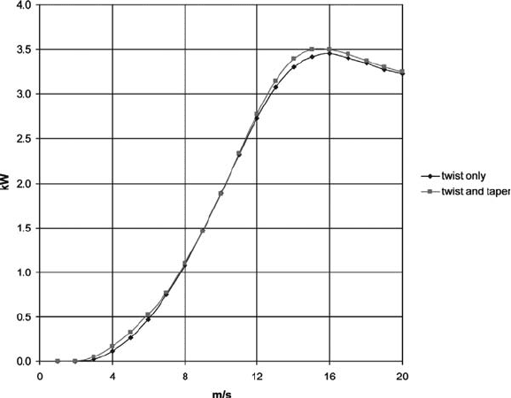
turing. For example, it is possible to extrude plastic blades, such that there will be
twist but no taper. The effect on effi ciency is illustrated on Fig. 12 . The lower
Figure 12: Effect of adding taper to a blade with twist only.
Design and Development of Small Wind Turbines 267
effi ciency at lower wind speeds can be signifi cant in terms of energy production,
as a typical small turbine spends much of its life operating at low wind speeds.
On the smaller turbines, it is also possible to have more than three blades with
relatively little impact on cost. Multiple blades allow higher starting torques, and
lower operational speed (and therefore lower noise). This must be traded off
against higher thrust loads and the slightly higher cost. On some of the smallest
machines there is no rotor overspeed control at all, i.e. the machine is simply
designed to survive the high rotational speed and thrust load of a “runaway” condi-
tion. In this case having multiple blades (e.g. the well-proven Rutland 913, which
has six blades) limits the rotational speed to some extent.
The hub is part of the rotor, and small wind turbines typically have very simple
hubs, as the blade pitch is typically fi xed. On some rotors blade pitch is not adjust-
able, other rotors use shims to set the pitch, while others use a rotary adjustment at
the blade root that is locked in place after fi nal adjustment. Some small wind tur-
bines have more complex hubs, consisting of springs and hinges (e.g. Proven wind
turbines, which pitch the blades to stall for overspeed control). None of these
features are typical of large wind turbines.
1.3 System design
1.3.1 DC systems
Traditionally small wind turbines use DC generators. The DC generator is now
usually in fact a permanent magnet three-phase synchronous AC generator (alter-
nator), with a diode rectifi er either located up in the turbine (with two wires com-
ing down the tower) or at the control panel (with three smaller wires coming down
the tower). The rotor mounts directly onto the alternator shaft, and no gearbox is
required. This remains the most common approach used by small wind turbine
designers. With the advent of grid-tie inverters (see below), it is a solution that
makes small wind turbines suitable for battery charging as well as grid-connected
applications.
In the battery charging mode, DC systems operate at fairly constant speed.
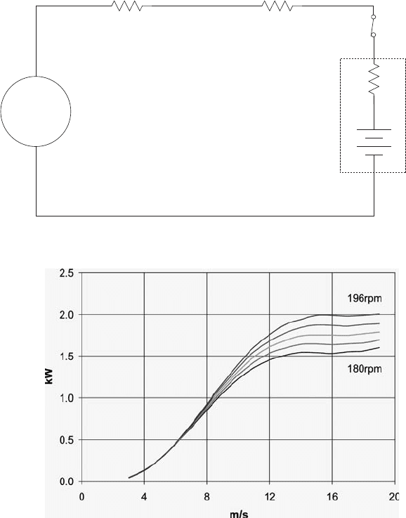
Figure 13 shows the simplifi ed equivalent circuit of such a system. The voltage pro-
duced by the generator is proportional to rotational speed. If the sum of the circuit
resistances (generator winding resistance, cable resistance and battery resistance) is
relatively small, then V
gen
≅ V
batt
, i.e. the battery voltage effectively regulates the
generator voltage, and therefore the generator speed, to be relatively constant.
In real applications the generator rotational speed increases noticeably with
power output, as suggested by Fig. 13 . When current is high, then voltage drop
across the resistances is signifi cant, and V
gen
rises (and therefore generator rota-
tional speed) with power output. This impacts aerodynamic performance and
design. For example, if a stalling airfoil is being relied upon to limit power output,
the power output at which stall occurs is a function of rotational speed as sug-
gested by Fig. 14 . When batteries reach a fully charged condition, the charge con-
troller disconnects the wind turbine and the wind turbine freewheels, held back
only by the overspeed control system.
268 Wind Power Generation and Wind Turbine Design
Besides not needing a gearbox, DC systems can use the permanent magnet gen-
erator as a brake. The windings need only be shorted or connected across a small
resistance, and this results in signifi cant braking torque from the generator. It is
typical for DC machines, during the commissioning process, to have their winding
shorted until such time as the turbine is ready to rotate.
1.3.2 AC systems
1.3.2.1 Permanent magnet alternator with grid-tie inverter
This approach is commonly used for machines up to about 10 kW to produce
grid-quality AC power. Above this level (and sometimes below), a gearbox
Figure 14: Relative impact of rotational speed on maximum rotor power.
DC
generator
winding
resistance
cable
resistance
Battery
Vbatt
Vgen
charge
control
Figure 13: Simplifi ed battery charging circuit.
Design and Development of Small Wind Turbines 269
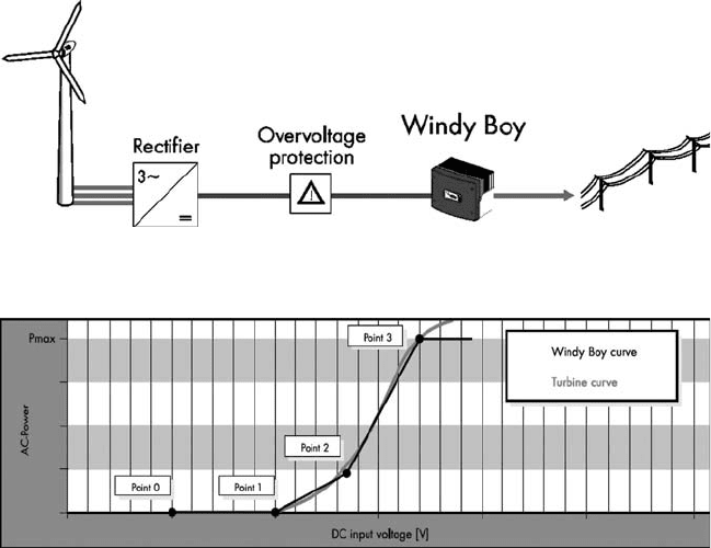
and an asynchronous generator are typically used (see below). Figure 15
shows the general arrangement for this approach. In this case three-phase
power (variable voltage and variable frequency) comes down the tower. It is
then rectified to DC, passes through an overvoltage protection relay and on
to the inverter.
The grid-tie inverter loads the turbine (i.e. extracts power) on the basis of volt-
age (i.e. turbine rpm). In this way the turbine can be operated at or near the point
of optimum system effi ciency all along the power curve, as illustrated in Fig. 16 .
As the wind starts to rise, the DC voltage increases. As the voltage rises above
point 1, the inverter begins to load the turbine according to the line between points
1 and 2. As the voltage rises above point 2, the inverter begins to load the turbine
according to the line between points 2 and 3.
Above point 3 the rated power of the inverter is reached, and so regardless of
voltage (i.e. turbine rotational speed), the turbine is only loaded to that power. This
means that the turbine accelerates, since rotor power exceeds the power being
withdrawn by the generator. In this case the overspeed control system comes into
play, regulating the turbine rpm below a dangerous level. If the DC voltage rises to
a value that exceeds the input rating of the inverter (if, e.g. the overspeed control
mechanism fails), then the overvoltage circuit shown in Fig. 15 will disconnect the
turbine from the inverter input. Inverter effi ciency is poor at low power inputs, but
then typically rises to a high level.
Figure 15: General arrangement of grid-tie inverter system (credit: SMA).
Figure 16: Grid-tie inverter programming (credit: SMA).
270 Wind Power Generation and Wind Turbine Design
1.3.2.2 Induction (asynchronous) generator with gearbox
Induction generators are the most commonly used generators in large wind sys-
tems. They are simple, rugged, and relatively low cost. However they have high
rotational speed compared to DC systems, and therefore necessitate the use of
a gearbox. Small wind turbines rotate at higher speeds than large ones, and it is
therefore easier to use the permanent magnet alternator design approach than on
larger turbines. However it is also true that on small induction generator-based
machines the gear ratio is lower than on large wind turbines, and so this can result
in a somewhat simpler power transmission (fewer reduction stages) than on large
wind turbines.
Small induction generator-based wind turbines operate at close to constant
speed. This means that the wind system only operates at the peak of the C
p
− l
curve at one wind speed, therefore at other wind speeds the turbine operates at less
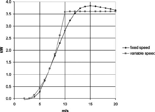
than peak effi ciency. Figure 17 illustrates the difference in rotor power between
fi xed and variable speed operation of the same rotor. When the effi ciency of the
inverter is taken into account, it can be expected that variable speed operation can
result in 5 − 10% more energy capture.
1.3.3 Braking systems
Many small wind turbines have no braking systems at all (except for the rotor
overspeed control discussed above). As mentioned above, permanent magnet gen-
erators are sometimes used as brakes, which can be accomplished by either sim-
ply shorting the windings or connecting the windings through a low electrical
resistance.
It is also possible to use the generator as a brake on an induction machine (e.g.
the AOC 15/50, see Fig. 6 ). This is sometimes called “electrodynamic braking”.
Figure 17: Fixed vs. variable speed power curves.
Design and Development of Small Wind Turbines 271
The generator is disconnected from the grid and then connected to a series-parallel
combination of resistors and capacitors. The capacitors provide the excitation and
the resistors dissipate the energy. It provides very smooth braking torque until
excitation is lost at a low rpm, and a small disc brake is engaged.
A disc brake is commonly used on large wind turbines, and is sometimes used
on small machines. The Enertech 1500 ( Fig. 5 ) had a gearbox, induction generator,
and a disc brake on the high speed shaft. The drawback of this arrangement was
that the brake had to be sized for the maximum anticipated rotor torque, and so
every time the rotor was halted the drivetrain (and particularly the gearbox) expe-
rienced maximum torque. Often a disc brake produces torque spikes as the discs
come together, rebound and then fi nally settle. It is also possible to put the disc
brake on the low-speed shaft, thereby eliminating strain on the gearbox, but a
much bigger brake is required and so this is seldom used.
Other creative ideas have been tried, such as the so-called “hydraulic brake”. In
this case a hydraulic pump is coupled onto the high speed shaft rather than a disc
brake. Hydraulic fl uid is pumped through an open solenoid valve during normal
operation, and when braking action is required the solenoid valve is closed and the
fl ow diverts through a pressure relief valve. This produces very smooth braking
torque, however there are pumping losses during normal turbine operation.
1.3.4 Power cabling
Typically on small wind turbines power cabling comes from the generator to slip
rings, and then a separate power cable goes down the tower to a disconnect switch
at the base of the tower. However the “twist cable” concept was introduced in the
early 1980s, and is now typically used on large machines, and sometimes used on
small machines.
The power cable is suspended from beneath the turbine, supported by a strain
relief connection at the turbine. Depending on the cable length and fl exibility, it is
generally able to withstand many yaw revolutions in one direction before it is in
mechanical stress. The cable is physically disconnected at the bottom of the tower
and allowed to unwind during service visits to the turbine. In the case of large wind
turbines, yaw revolutions are counted, and when a certain number have accumu-
lated in one direction the turbine is stopped and the cable is “unwound” via the
yaw mechanism.
1.3.5 Control system design
The control system depends very much on the application, and in general there
are two applications: grid connected and battery charging (though there are other
applications such as direct heating and direct pumping).
1.3.5.1 Grid-connected control systems
This is discussed to some extent in Section 1.3.2, and the controls depend on
whether it is a grid-tie inverter system or an induction generator-based system.
In the case of the former, the inverter effectively is the control system, load-
ing the generator according to the DC voltage that it sees as discussed above.
272 Wind Power Generation and Wind Turbine Design
The inverter would also include grid protection functions according to utility
standards. In the European Union this would typically be EN50438 [ 3 ], whereas
standards vary in the USA. Grid protection is primarily required to disconnect
the wind system from the grid in the event that the power produced is outside of
a frequency/voltage window (i.e. either the voltage or frequency going too high
or too low). This would suggest that a utility power outage has occurred and that
the inverter output is being fed into a “dead” line, thereby endangering utility
linemen.
An induction generator-based system would also have grid protection functions
according to EN50438. It would also have logic to connect and disconnect the
generator from the grid, usually based on generator rotation speed (rpm).
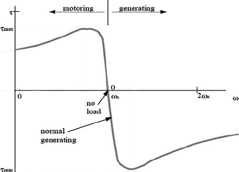
Figure 18 shows the induction machine speed − torque curve. Torque is produced
by the machine as it motors up to speed from a stopped condition. When driven
beyond the synchronous speed ( w
s
) it absorbs torque (and produces electrical
power). Normal (full load) generating torque is indicated on the curve. Therefore
the control action would allow the turbine to be driven up to synchronous speed by
the wind, and at w
s
connect it to the grid. Similarly when the rotational speed
drops below w
s
the machine is consuming power and so the control system discon-
nects it from the grid.
There are a number of possible variations on this approach. For example, it
could be connected on the basis of rpm as above, but disconnected on the basis of
power (i.e. when power is being consumed). Since precise connection at w
s
is
needed (consider the torque spike that would result if connection occurred at w
s
+
10%), rate-of-change of w could be integrated into the control algorithm. In some
turbines (Enertech and AOC) the machine was actually motored up to speed
(sometimes stalling airfoils have poor self-starting characteristics) when wind
speed was deemed suffi cient to generate power.
Figure 18: Induction machine speed − torque curve.
Design and Development of Small Wind Turbines 273
1.3.5.2 Battery charging control systems
In general, permanent magnet generators are used on small DC wind systems, and
so the function of the control system is to intelligently connect or disconnect the
wind turbine from the battery depending on the battery state of charge, which is a
function of battery voltage (see Fig. 13 ). Control systems can also control charge
rate, e.g. trickle charging the battery through resistors as the batteries approach
full charge.
The control system may also connect the generator output to braking resistors to
limit rotational speed in the case where the battery is fully charged. Commonly in
this case, however, the turbine is simply electrically disconnected and the mechan-
ical overspeed mechanism comes into play.
1.4 Tower design
Towers can be grouped into two categories: guyed towers and self-supporting
towers. Large wind turbine towers are generally only the self-supporting type –
typically tapered tubular steel towers. For small wind turbines, self-supporting
towers generally come in three types: lattice towers ( Figs 6 and 8 ), steel poles,
and wood poles (phone poles). Self-supporting towers are more expensive than
the guyed variety for a given height, and primarily for this reason the guyed tow-
ers are more commonly used in small wind turbine applications. However if there
is inadequate room on the site to accommodate the guy wires, a self-supporting
tower is used.
Guyed towers come in two types: guyed poles or guyed lattice towers. These are
both mass-produced for use in the telecommunications industry. Guyed poles are
illustrated in Figs 3 , 7 , and 11 , and guyed lattice towers are shown in Figs 5 and 9 .
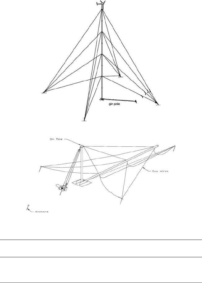
Figure 19 shows a tall guyed pole for a small wind turbine, with several levels of
guys and an integral gin pole. Figs 9 and 20 show how the gin pole is used to erect
the tower. This tilt-up technique makes it possible to erect and service a turbine
without the need for a crane or climbing equipment.
It is often cost-effective to consider a rather high tower for a small wind turbine,
as the incremental cost of increased height is low, and meanwhile the increase in
wind speed (and reduced turbulence) increase production signifi cantly. Consider
the case of a Bergey XL1, with measured annual average winds of 5 m/s at a height
of 10 m. Table 1 shows the energy production, indicative system cost, and payback
time, assuming the energy is worth $0.20/kWh. On this basis it makes sense to
purchase the tallest tower.
Recently roof-mounted systems have become somewhat popular (not unlike
Fig. 4 , but mounted on e.g. a gable end). Even though at fi rst consideration it
seems that this is an inexpensive way of getting a turbine up “into the wind”, the
concept suffers from several disadvantages; rooftops are not actually very high,
winds at the rooftop tend to be turbulent, structural properties of roofs vary result-
ing in the possible need for (expensive) custom design work, and only the smallest
turbines can physically mount on roofs which means energy capture will be limited.
274 Wind Power Generation and Wind Turbine Design
Figure 19: Guyed pole tower (credit: Bergey).
Figure 20: Tilt-up tower installation (credit: NRG).
Table 1: Effect of tower height on economics.
Tower height (m) Annual kWh System cost ($)
Annual energy
value ($)
Payback
(years)
18 2300 7800 460 17.0
24 2600 8250 520 15.9
30 2800 8600 560 15.4
The present author cannot recommend roof-mounted wind systems in general, and
increasing numbers of people concur [ 4 , 5 ].
2 Future developments
A number of areas are being explored by an ever-increasing number of small wind
turbine companies, with a view toward increasing reliability and reducing cost.
