Tanenbaum A. Computer Networks
Подождите немного. Документ загружается.

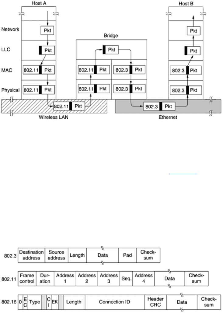
its way upward. In the MAC sublayer in the bridge, the 802.11 header is stripped off. The bare
packet (with LLC header) is then handed off to the LLC sublayer in the bridge. In this example,
the packet is destined for an 802.3 LAN, so it works its way down the 802.3 side of the bridge
and off it goes on the Ethernet. Note that a bridge connecting
k different LANs will have k
different MAC sublayers and
k different physical layers, one for each type.
Figure 4-40. Operation of a LAN bridge from 802.11 to 802.3.
So far it looks like moving a frame from one LAN to another is easy. Such is not the case. In
this section we will point out some of the difficulties that one encounters when trying to build a
bridge between the various 802 LANs (and MANs). We will focus on 802.3, 802.11, and
802.16, but there are others as well, each with its unique problems.
To start with, each of the LANs uses a different frame format (see
Fig. 4-41). Unlike the
differences between Ethernet, token bus, and token ring, which were due to history and big
corporate egos, here the differences are to some extent legitimate. For example, the
Duration
field in 802.11 is there due to the MACAW protocol and makes no sense in Ethernet. As a
result, any copying between different LANs requires reformatting, which takes CPU time,
requires a new checksum calculation, and introduces the possibility of undetected errors due to
bad bits in the bridge's memory.
Figure 4-41. The IEEE 802 frame formats. The drawing is not to scale.
A second problem is that interconnected LANs do not necessarily run at the same data rate.
When forwarding a long run of back-to-back frames from a fast LAN to a slower one, the
bridge will not be able to get rid of the frames as fast as they come in. For example, if a
gigabit Ethernet is pouring bits into an 11-Mbps 802.11b LAN at top speed, the bridge will
have to buffer them, hoping not to run out of memory. Bridges that connect three or more
241

LANs have a similar problem when several LANs are trying to feed the same output LAN at the
same time even if all the LANs run at the same speed.
A third problem, and potentially the most serious of all, is that different 802 LANs have
different maximum frame lengths. An obvious problem arises when a long frame must be
forwarded onto a LAN that cannot accept it. Splitting the frame into pieces is out of the
question in this layer. All the protocols assume that frames either arrive or they do not. There
is no provision for reassembling frames out of smaller units. This is not to say that such
protocols could not be devised. They could be and have been. It is just that no data link
protocols provide this feature, so bridges must keep their hands off the frame payload.
Basically, there is no solution. Frames that are too large to be forwarded must be discarded.
So much for transparency.
Another point is security. Both 802.11 and 802.16 support encryption in the data link layer.
Ethernet does not. This means that the various encryption services available to the wireless
networks are lost when traffic passes over an Ethernet. Worse yet, if a wireless station uses
data link layer encryption, there will be no way to decrypt it when it arrives over an Ethernet.
If the wireless station does not use encryption, its traffic will be exposed over the air link.
Either way there is a problem.
One solution to the security problem is to do encryption in a higher layer, but then the 802.11
station has to know whether it is talking to another station on an 802.11 network (meaning
use data link layer encryption) or not (meaning do not use it). Forcing the station to make a
choice destroys transparency.
A final point is quality of service. Both 802.11 and 802.16 provide it in various forms, the
former using PCF mode and the latter using constant bit rate connections. Ethernet has no
concept of quality of service, so traffic from either of the others will lose its quality of service
when passing over an Ethernet.
4.7.2 Local Internetworking
The previous section dealt with the problems encountered in connecting two different IEEE 802
LANs via a single bridge. However, in large organizations with many LANs, just interconnecting
them all raises a variety of issues, even if they are all just Ethernet. Ideally, it should be
possible to go out and buy bridges designed to the IEEE standard, plug the connectors into the
bridges, and everything should work perfectly, instantly. There should be no hardware changes
required, no software changes required, no setting of address switches, no downloading of
routing tables or parameters, nothing. Just plug in the cables and walk away. Furthermore, the
operation of the existing LANs should not be affected by the bridges at all. In other words, the
bridges should be completely transparent (invisible to all the hardware and software).
Surprisingly enough, this is actually possible. Let us now take a look at how this magic is
accomplished.
In its simplest form, a transparent bridge operates in promiscuous mode, accepting every
frame transmitted on all the LANs to which it is attached. As an example, consider the
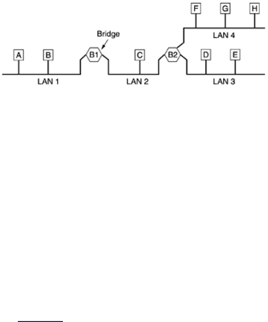
configuration of
Fig. 4-42. Bridge B1 is connected to LANs 1 and 2, and bridge B2 is connected
to LANs 2, 3, and 4. A frame arriving at bridge B1 on LAN 1 destined for
A can be discarded
immediately, because it is already on the correct LAN, but a frame arriving on LAN 1 for
C or F
must be forwarded.
Figure 4-42. A configuration with four LANs and two bridges.
242
When a frame arrives, a bridge must decide whether to discard or forward it, and if the latter,
on which LAN to put the frame. This decision is made by looking up the destination address in
a big (hash) table inside the bridge. The table can list each possible destination and tell which
output line (LAN) it belongs on. For example, B2's table would list
A as belonging to LAN 2,
since all B2 has to know is which LAN to put frames for
A on. That, in fact, more forwarding
happens later is not of interest to it.
When the bridges are first plugged in, all the hash tables are empty. None of the bridges know
where any of the destinations are, so they use a flooding algorithm: every incoming frame for
an unknown destination is output on all the LANs to which the bridge is connected except the
one it arrived on. As time goes on, the bridges learn where destinations are, as described
below. Once a destination is known, frames destined for it are put on only the proper LAN and
are not flooded.
The algorithm used by the transparent bridges is
backward learning.As mentioned above,
the bridges operate in promiscuous mode, so they see every frame sent on any of their LANs.
By looking at the source address, they can tell which machine is accessible on which LAN. For
example, if bridge B1 in
Fig. 4-42 sees a frame on LAN 2 coming from C, it knows that C must
be reachable via LAN 2, so it makes an entry in its hash table noting that frames going to
C
should use LAN 2. Any subsequent frame addressed to
C coming in on LAN 1 will be forwarded,
but a frame for
C coming in on LAN 2 will be discarded.
The topology can change as machines and bridges are powered up and down and moved
around. To handle dynamic topologies, whenever a hash table entry is made, the arrival time
of the frame is noted in the entry. Whenever a frame whose source is already in the table
arrives, its entry is updated with the current time. Thus, the time associated with every entry
tells the last time a frame from that machine was seen.
Periodically, a process in the bridge scans the hash table and purges all entries more than a
few minutes old. In this way, if a computer is unplugged from its LAN, moved around the
building, and plugged in again somewhere else, within a few minutes it will be back in normal
operation, without any manual intervention. This algorithm also means that if a machine is
quiet for a few minutes, any traffic sent to it will have to be flooded until it next sends a frame
itself.
The routing procedure for an incoming frame depends on the LAN it arrives on (the source
LAN) and the LAN its destination is on (the destination LAN), as follows:
1. If destination and source LANs are the same, discard the frame.
2. If the destination and source LANs are different, forward the frame.
3. If the destination LAN is unknown, use flooding.
As each frame arrives, this algorithm must be applied. Special-purpose VLSI chips do the
lookup and update the table entry, all in a few microseconds.
243
4.7.3 Spanning Tree Bridges
To increase reliability, some sites use two or more bridges in parallel between pairs of LANs, as
shown in
Fig. 4-43. This arrangement, however, also introduces some additional problems
because it creates loops in the topology.
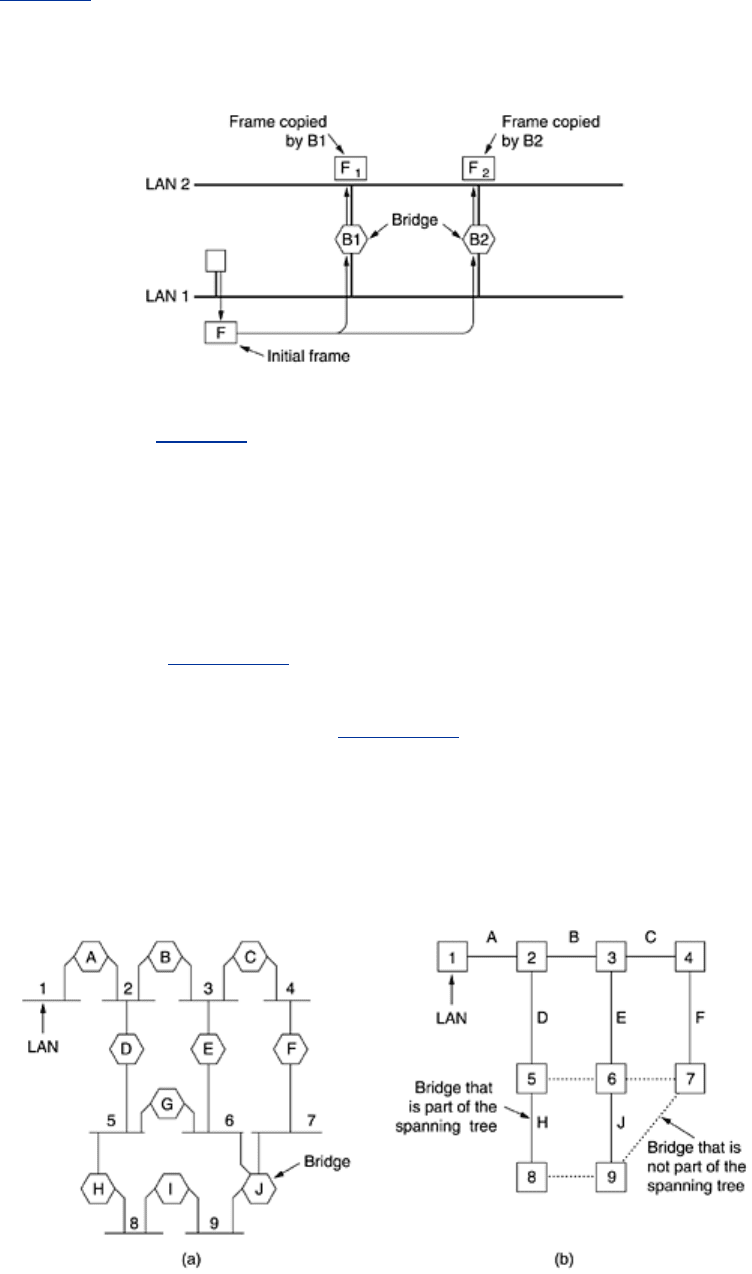
Figure 4-43. Two parallel transparent bridges.
A simple example of these problems can be seen by observing how a frame,
F, with unknown
destination is handled in
Fig. 4-43. Each bridge, following the normal rules for handling
unknown destinations, uses flooding, which in this example just means copying it to LAN 2.
Shortly thereafter, bridge 1 sees
F
2
, a frame with an unknown destination, which it copies to
LAN 1, generating
F
3
(not shown). Similarly, bridge 2 copies F
1
to LAN 1 generating F
4
(also
not shown). Bridge 1 now forwards
F
4
and bridge 2 copies F
3
. This cycle goes on forever.
The solution to this difficulty is for the bridges to communicate with each other and overlay the
actual topology with a spanning tree that reaches every LAN. In effect, some potential
connections between LANs are ignored in the interest of constructing a fictitious loop-free
topology. For example, in
Fig. 4-44(a) we see nine LANs interconnected by ten bridges. This
configuration can be abstracted into a graph with the LANs as the nodes. An arc connects any
two LANs that are connected by a bridge. The graph can be reduced to a spanning tree by
dropping the arcs shown as dotted lines in
Fig. 4-44(b). Using this spanning tree, there is
exactly one path from every LAN to every other LAN. Once the bridges have agreed on the
spanning tree, all forwarding between LANs follows the spanning tree. Since there is a unique
path from each source to each destination, loops are impossible.
Figure 4-44. (a) Interconnected LANs. (b) A spanning tree covering
the LANs. The dotted lines are not part of the spanning tree.
244

To build the spanning tree, first the bridges have to choose one bridge to be the root of the
tree. They make this choice by having each one broadcast its serial number, installed by the
manufacturer and guaranteed to be unique worldwide. The bridge with the lowest serial
number becomes the root. Next, a tree of shortest paths from the root to every bridge and
LAN is constructed. This tree is the spanning tree. If a bridge or LAN fails, a new one is
computed.
The result of this algorithm is that a unique path is established from every LAN to the root and
thus to every other LAN. Although the tree spans all the LANs, not all the bridges are
necessarily present in the tree (to prevent loops). Even after the spanning tree has been
established, the algorithm continues to run during normal operation in order to automatically
detect topology changes and update the tree. The distributed algorithm used for constructing
the spanning tree was invented by Radia Perlman and is described in detail in (Perlman, 2000).
It is standardized in IEEE 802.1D.
4.7.4 Remote Bridges
A common use of bridges is to connect two (or more) distant LANs. For example, a company
might have plants in several cities, each with its own LAN. Ideally, all the LANs should be
interconnected, so the complete system acts like one large LAN.
This goal can be achieved by putting a bridge on each LAN and connecting the bridges pairwise
with point-to-point lines (e.g., lines leased from a telephone company). A simple system, with
three LANs, is illustrated in
Fig. 4-45. The usual routing algorithms apply here. The simplest
way to see this is to regard the three point-to-point lines as hostless LANs. Then we have a
normal system of six LANS interconnected by four bridges. Nothing in what we have studied so
far says that a LAN must have hosts on it.
Figure 4-45. Remote bridges can be used to interconnect distant LANs.
Various protocols can be used on the point-to-point lines. One possibility is to choose some
standard point-to-point data link protocol such as PPP, putting complete MAC frames in the
payload field. This strategy works best if all the LANs are identical, and the only problem is
getting frames to the correct LAN. Another option is to strip off the MAC header and trailer at
the source bridge and put what is left in the payload field of the point-to-point protocol. A new
MAC header and trailer can then be generated at the destination bridge. A disadvantage of this
approach is that the checksum that arrives at the destination host is not the one computed by
the source host, so errors caused by bad bits in a bridge's memory may not be detected.
4.7.5 Repeaters, Hubs, Bridges, Switches, Routers, and Gateways
So far in this book we have looked at a variety of ways to get frames and packets from one
cable segment to another. We have mentioned repeaters, bridges, switches, hubs, routers, and
gateways. All of these devices are in common use, but they all differ in subtle and not-so-
subtle ways. Since there are so many of them, it is probably worth taking a look at them
together to see what the similarities and differences are.
245
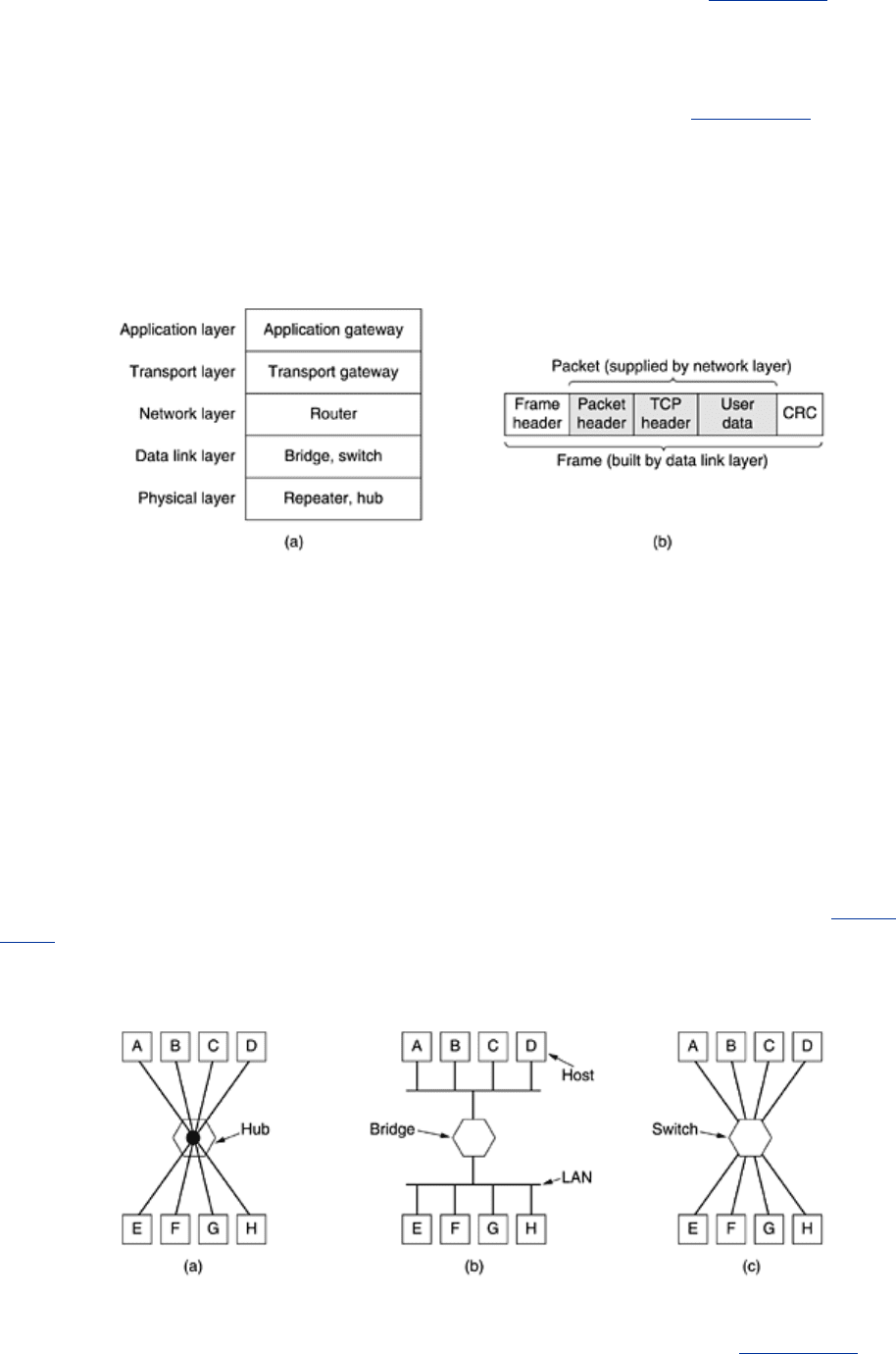
To start with, these devices operate in different layers, as illustrated in Fig. 4-46(a). The layer
matters because different devices use different pieces of information to decide how to switch.
In a typical scenario, the user generates some data to be sent to a remote machine. Those
data are passed to the transport layer, which then adds a header, for example, a TCP header,
and passes the resulting unit down to the network layer. The network layer adds its own
header to form a network layer packet, for example, an IP packet. In
Fig. 4-46(b) we see the
IP packet shaded in gray. Then the packet goes to the data link layer, which adds its own
header and checksum (CRC) and gives the resulting frame to the physical layer for
transmission, for example, over a LAN.
Figure 4-46. (a) Which device is in which layer. (b) Frames, packets,
and headers.
Now let us look at the switching devices and see how they relate to the packets and frames. At
the bottom, in the physical layer, we find the repeaters. These are analog devices that are
connected to two cable segments. A signal appearing on one of them is amplified and put out
on the other. Repeaters do not understand frames, packets, or headers. They understand
volts. Classic Ethernet, for example, was designed to allow four repeaters, in order to extend
the maximum cable length from 500 meters to 2500 meters.
Next we come to the hubs. A hub has a number of input lines that it joins electrically. Frames
arriving on any of the lines are sent out on all the others. If two frames arrive at the same
time, they will collide, just as on a coaxial cable. In other words, the entire hub forms a single
collision domain. All the lines coming into a hub must operate at the same speed. Hubs differ
from repeaters in that they do not (usually) amplify the incoming signals and are designed to
hold multiple line cards each with multiple inputs, but the differences are slight. Like repeaters,
hubs do not examine the 802 addresses or use them in any way. A hub is shown in
Fig. 4-
47(a).
Figure 4-47. (a) A hub. (b) A bridge. (c) A switch.
Now let us move up to the data link layer where we find bridges and switches. We just studied
bridges at some length. A bridge connects two or more LANs, as shown in
Fig. 4-47(b). When
a frame arrives, software in the bridge extracts the destination address from the frame header
246

and looks it up in a table to see where to send the frame. For Ethernet, this address is the 48-
bit destination address shown in
Fig. 4-17. Like a hub, a modern bridge has line cards, usually
for four or eight input lines of a certain type. A line card for Ethernet cannot handle, say, token
ring frames, because it does not know where to find the destination address in the frame
header. However, a bridge may have line cards for different network types and different
speeds. With a bridge, each line is its own collision domain, in contrast to a hub.
Switches are similar to bridges in that both route on frame addresses. In fact, many people
uses the terms interchangeably. The main difference is that a switch is most often used to
connect individual computers, as shown in
Fig. 4-47(c). As a consequence, when host A in Fig.
4-47(b) wants to send a frame to host B, the bridge gets the frame but just discards it. In
contrast, in
Fig. 4-47(c), the switch must actively forward the frame from A to B because there
is no other way for the frame to get there. Since each switch port usually goes to a single
computer, switches must have space for many more line cards than do bridges intended to
connect only LANs. Each line card provides buffer space for frames arriving on its ports. Since
each port is its own collision domain, switches never lose frames to collisions. However, if
frames come in faster than they can be retransmitted, the switch may run out of buffer space
and have to start discarding frames.
To alleviate this problem slightly, modern switches start forwarding frames as soon as the
destination header field has come in, but before the rest of the frame has arrived (provided the
output line is available, of course). These switches do not use store-and-forward switching.
Sometimes they are referred to as
cut-through switches. Usually, cut-through is handled
entirely in hardware, whereas bridges traditionally contained an actual CPU that did store-and-
forward switching in software. But since all modern bridges and switches contain special
integrated circuits for switching, the difference between a switch and bridge is more a
marketing issue than a technical one.
So far we have seen repeaters and hubs, which are quite similar, as well as bridges and
switches, which are also very similar to each other. Now we move up to routers, which are
different from all of the above. When a packet comes into a router, the frame header and
trailer are stripped off and the packet located in the frame's payload field (shaded in
Fig. 4-46)
is passed to the routing software. This software uses the packet header to choose an output
line. For an IP packet, the packet header will contain a 32-bit (IPv4) or 128-bit (IPv6) address,
but not a 48-bit 802 address. The routing software does not see the frame addresses and does
not even know whether the packet came in on a LAN or a point-to-point line. We will study
routers and routing in
Chap. 5.
Up another layer we find transport gateways. These connect two computers that use different
connection-oriented transport protocols. For example, suppose a computer using the
connection-oriented TCP/IP protocol needs to talk to a computer using the connection-oriented
ATM transport protocol. The transport gateway can copy the packets from one connection to
the other, reformatting them as need be.
Finally, application gateways understand the format and contents of the data and translate
messages from one format to another. An e-mail gateway could translate Internet messages
into SMS messages for mobile phones, for example.
4.7.6 Virtual LANs
In the early days of local area networking, thick yellow cables snaked through the cable ducts
of many office buildings. Every computer they passed was plugged in. Often there were many
cables, which were connected to a central backbone (as in
Fig. 4-39) or to a central hub. No
thought was given to which computer belonged on which LAN. All the people in adjacent offices
were put on the same LAN whether they belonged together or not. Geography trumped logic.
247
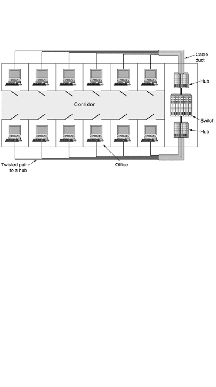
With the advent of 10Base-T and hubs in the 1990s, all that changed. Buildings were rewired
(at considerable expense) to rip out all the yellow garden hoses and install twisted pairs from
every office to central wiring closets at the end of each corridor or in a central machine room,
as illustrated in
Fig. 4-48. If the Vice President in Charge of Wiring was a visionary, category 5
twisted pairs were installed; if he was a bean counter, the existing (category 3) telephone
wiring was used (only to be replaced a few years later when fast Ethernet emerged).
Figure 4-48. A building with centralized wiring using hubs and a
switch.
With hubbed (and later, switched) Ethernet, it was often possible to configure LANs logically
rather than physically. If a company wants
k LANs, it buys k hubs. By carefully choosing which
connectors to plug into which hubs, the occupants of a LAN can be chosen in a way that makes
organizational sense, without too much regard to geography. Of course, if two people in the
same department work in different buildings, they are probably going to be on different hubs
and thus different LANs. Nevertheless, the situation is a lot better than having LAN
membership entirely based on geography.
Does it matter who is on which LAN? After all, in virtually all organizations, all the LANs are
interconnected. In short, yes, it often matters. Network administrators like to group users on
LANs to reflect the organizational structure rather than the physical layout of the building for a
variety of reasons. One issue is security. Any network interface can be put in promiscuous
mode, copying all the traffic that comes down the pipe. Many departments, such as research,
patents, and accounting, have information that they do not want passed outside their
department. In such a situation, putting all the people in a department on a single LAN and not
letting any of that traffic off the LAN makes sense. Management does not like hearing that
such an arrangement is impossible unless all the people in each department are located in
adjacent offices with no interlopers.
A second issue is load. Some LANs are more heavily used than others and it may be desirable
to separate them at times. For example, if the folks in research are running all kinds of nifty
experiments that sometimes get out of hand and saturate their LAN, the folks in accounting
may not be enthusiastic about donating some of their capacity to help out.
A third issue is broadcasting. Most LANs support broadcasting, and many upper-layer protocols
use this feature extensively. For example, when a user wants to send a packet to an IP
address
x, how does it know which MAC address to put in the frame? We will study this
question in
Chap. 5, but briefly summarized, the answer is that it broadcasts a frame
containing the question: Who owns IP address
x? Then it waits for an answer. And there are
248

many more examples of where broadcasting is used. As more and more LANs get
interconnected, the number of broadcasts passing each machine tends to increase linearly with
the number of machines.
Related to broadcasts is the problem that once in a while a network interface will break down
and begin generating an endless stream of broadcast frames. The result of this
broadcast
storm
is that (1) the entire LAN capacity is occupied by these frames, and (2) all the machines
on all the interconnected LANs are crippled just processing and discarding all the frames being
broadcast.
At first it might appear that broadcast storms could be limited in scope by separating the LANs
with bridges or switches, but if the goal is to achieve transparency (i.e., a machine can be
moved to a different LAN across the bridge without anyone noticing it), then bridges have to
forward broadcast frames.
Having seen why companies might want multiple LANs with restricted scope, let us get back to
the problem of decoupling the logical topology from the physical topology. Suppose that a user
gets shifted within the company from one department to another without changing offices or
changes offices without changing departments. With hubbed wiring, moving the user to the
correct LAN means having the network administrator walk down to the wiring closet and pull
the connector for the user's machine from one hub and put it into a new hub.
In many companies, organizational changes occur all the time, meaning that system
administrators spend a lot of time pulling out plugs and pushing them back in somewhere else.
Also, in some cases, the change cannot be made at all because the twisted pair from the user's
machine is too far from the correct hub (e.g., in the wrong building).
In response to user requests for more flexibility, network vendors began working on a way to
rewire buildings entirely in software. The resulting concept is called a
VLAN (Virtual LAN) and
has even been standardized by the 802 committee. It is now being deployed in many
organizations. Let us now take a look at it. For additional information about VLANs, see
(Breyer and Riley, 1999; and Seifert, 2000).
VLANs are based on specially-designed VLAN-aware switches, although they may also have
some hubs on the periphery, as in
Fig. 4-48. To set up a VLAN-based network, the network
administrator decides how many VLANs there will be, which computers will be on which VLAN,
and what the VLANs will be called. Often the VLANs are (informally) named by colors, since it
is then possible to print color diagrams showing the physical layout of the machines, with the
members of the red LAN in red, members of the green LAN in green, and so on. In this way,
both the physical and logical layouts are visible in a single view.
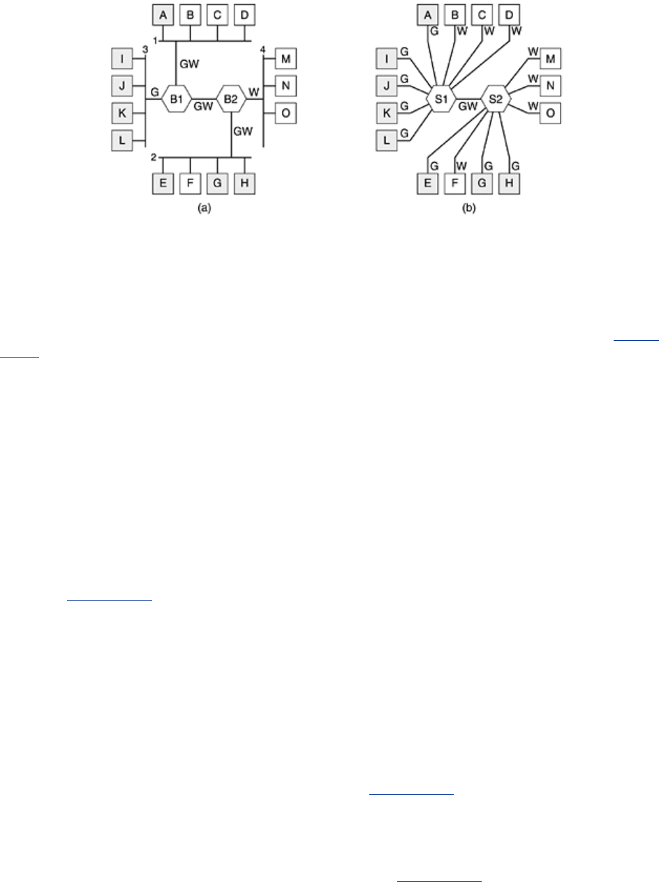
As an example, consider the four LANs of
Fig. 4-49(a), in which eight of the machines belong
to the G (gray) VLAN and seven of them belong to the W (white) VLAN. The four physical LANs
are connected by two bridges,
B1 and B2. If centralized twisted pair wiring is used, there
might also be four hubs (not shown), but logically a multidrop cable and a hub are the same
thing. Drawing it this way just makes the figure a little less cluttered. Also, the term ''bridge''
tends to be used nowadays mostly when there are multiple machines on each port, as in this
figure, but otherwise, ''bridge'' and ''switch'' are essentially interchangeable.
Fig. 4-49(b)
shows the same machines and same VLANs using switches with a single computer on each
port.
Figure 4-49. (a) Four physical LANs organized into two VLANs, gray
and white, by two bridges. (b) The same 15 machines organized into
two VLANs by switches.
249
To make the VLANs function correctly, configuration tables have to be set up in the bridges or
switches. These tables tell which VLANs are accessible via which ports (lines). When a frame
comes in from, say, the gray VLAN, it must be forwarded on all the ports marked G. This holds
for ordinary (i.e., unicast) traffic as well as for multicast and broadcast traffic.
Note that a port may be labeled with multiple VLAN colors. We see this most clearly in
Fig. 4-
49(a). Suppose that machine A broadcasts a frame. Bridge B1 receives the frame and sees
that it came from a machine on the gray VLAN, so it forwards it on all ports labeled G (except
the incoming port). Since
B1 has only two other ports and both of them are labeled G, the
frame is sent to both of them.
At
B2 the story is different. Here the bridge knows that there are no gray machines on LAN 4,
so the frame is not forwarded there. It goes only to LAN 2. If one of the users on LAN 4 should
change departments and be moved to the gray VLAN, then the tables inside
B2 have to be
updated to relabel that port as GW instead of W. If machine
F goes gray, then the port to LAN
2 has to be changed to G instead of GW.
Now let us imagine that all the machines on both LAN 2 and LAN 4 become gray. Then not only
do
B2's ports to LAN 2 and LAN 4 get marked G, but B1's port to B2 also has to change from
GW to G since white frames arriving at
B1 from LANs 1 and 3 no longer have to be forwarded
to
B2. In Fig. 4-49(b) the same situation holds, only here all the ports that go to a single
machine are labeled with a single color because only one VLAN is out there.
So far we have assumed that bridges and switches somehow know what color an incoming
frame is. How do they know this? Three methods are in use, as follows:
1. Every port is assigned a VLAN color.
2. Every MAC address is assigned a VLAN color.
3. Every layer 3 protocol or IP address is assigned a VLAN color.
In the first method, each port is labeled with VLAN color. However, this method only works if
all machines on a port belong to the same VLAN. In
Fig. 4-49(a), this property holds for B1 for
the port to LAN 3 but not for the port to LAN 1.
In the second method, the bridge or switch has a table listing the 48-bit MAC address of each
machine connected to it along with the VLAN that machine is on. Under these conditions, it is
possible to mix VLANs on a physical LAN, as in LAN 1 in
Fig. 4-49(a). When a frame arrives, all
the bridge or switch has to do is to extract the MAC address and look it up in a table to see
which VLAN the frame came from.
The third method is for the bridge or switch to examine the payload field of the frame, for
example, to classify all IP machines as belonging to one VLAN and all AppleTalk machines as
belonging to another. For the former, the IP address can also be used to identify the machine.
250