Singh R. Introduction to Basic Manufacturing Processes and Workshop Technology
Подождите немного. Документ загружается.

438 Introduction to Basic Manufacturing Processes and Workshop Technology
Table
Vise
Work
Tool
Tool post
Tool slide
Vertical tool feed
hand wheel
Table
support
Base
Table cross feed
mechanism
Cross rail
saddle
Ram
Drivin
g
mechanism
Column
Foundation
bolts
Ram lockin
g
clap
Shaper head
Swivel clamp
Ram position
Control nut
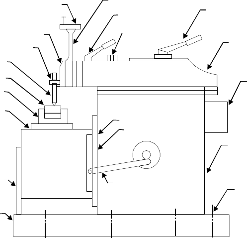
Fig. 23.5 Parts of a standard shaper
Base
It is rigid and heavy cast iron body to resist vibration and takes up high compressive
load. It supports all other parts of the machine, which are mounted over it. The base may
be rigidly bolted to the floor of the shop or on the bench according to the size of the machine.
Column
The column is a box shaped casting mounted upon the base. It houses the ram-driving
mechanism. Two accurately machined guide ways are provided on the top of the column on
which the ram reciprocates.
Cross rail
Cross rail of shaper has two parallel guide ways on its top in the vertical plane that is
perpendicular to the rai1 axis. It is mounted on the front vertical guide ways of the column.
It consists mechanism for raising and lowering the table to accommodate different sizes of
jobs by rotating an elevating screw which causes the cross rail to slide up and down on the
vertical face of the column. A horizontal cross feed screw is fitted within the cross rail and
parallel to the top guide ways of the cross rail. This screw actuates the table to move in a
crosswise direction.
Saddle
The saddle is located on the cross rail and holds the table on its top. Crosswise movement
of the saddle by rotation the cross feed screw by hand or power causes the table to move
sideways.
Table
The table is a box like casting having T -slots both on the top and sides for clamping the
Shaper, Planer and Slotter 439
work. It is bolted to the saddle and receives crosswise and vertical movements from the
saddle and cross rail.
Ram
It is the reciprocating part of the shaper, which reciprocates on the guideways provided
above the column. Ram is connected to the reciprocating mechanism contained within the
column.
Tool head
The tool head of a shaper performs the following functions-
(1) It holds the tool rigidly,
(2) It provides vertical and angular feed movement of the tool, and
(3) It allows the tool to have an automatic relief during its return stroke.
The various parts of tool head of shaper are apron clamping bolt, clapper box, tool post,
down feed, screw micrometer dial, down feed screw, vertical slide, apron washer, apron swivel
pin, and swivel base. By rotating the down feed screw handle, the vertical slide carrying the
tool gives down feed or angular feed movement while machining vertical or angular surface.
The amount of feed or depth of cut may be adjusted by a micrometer dial on the top of the
down feed screw. Apron consisting of clapper box, clapper block and tool post is clamped upon
the vertical slide by a screw. The two vertical walls on the apron called clapper box houses
the clapper block, which is connected to it by means of a hinge pin. The tool post is mounted
upon the clapper block. On the forward cutting stroke the clapper block fits securely to the
clapper box to make a rigid tool support. On the return stroke a slight frictional drag of the
tool on the work lifts the block out of the clapper box a sufficient amount preventing the tool
cutting edge from dragging and consequent wear. The work surface is also prevented from
any damage due to dragging.
23.5 SPECIFICATION OF A SHAPER
The size of a shaper is specified by the maximum length of stroke or cut it can
make. Usually the size of shaper ranges from 175 to 900 mm. Besides the length of
stroke, other particulars, such as the type of drive (belt drive or individual motor drive),
floor space required, weight of the machine, cutting to return stroke ratio, number and
amount of feed, power input etc. are also sometimes required for complete specification
of a shaper.
23.6 SHAPER MECHANISM
In a shaper, rotary motion of the drive is converted into reciprocating motion of the ram
by the mechanism housed within the column or the machine. In a standard shaper metal is
removed in the forward cutting stroke, while the return stroke goes idle and no metal is
removed during this period as shown in Fig. 23.4. The shaper mechanism is so designed that
it moves the ram holding the tool at a comparatively slower speed during forward cutting
stroke, whereas during the return stroke it allow the ram to move at a faster speed to reduce
the idle return time. This mechanism is known as quick return mechanism. The reciprocating
movement of the ram and the quick return mechanism of the machine are generally obtained
by anyone of the following methods:
440 Introduction to Basic Manufacturing Processes and Workshop Technology
(1) Crank and slotted link mechanism
(2) Whitworth quick return mechanism, and
(2) Hydraulic shaper mechanism
The crank and slotted link mechanism is discussed as under.
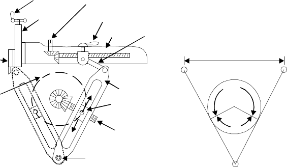
23.6.1 Crank and Slotted Link Mechanism
In crank and slotted link mechanism (Fig. 23.6), the pinion receives its motion from an
individual motor or overhead line shaft and transmits the motion or power to the bull gear.
Bull gear is a large gear mounted within the column. Speed of the bull gear may be changed
by different combination of gearing or by simply shifting the belt on the step cone pulley. A
radial slide is bolted to the centre of the bull gear. This radial slide carries a sliding block
into which the crank pin is fitted. Rotation of the bull gear will cause the bush pin to revolve
at a uniform speed. Sliding block, which is mounted upon the crank pin is fitted within the
slotted link. This slotted link is also known as the rocker arm. It is pivoted at its bottom end
attached to the frame of the column. The upper end of the rocker arm is forked and connected
to the ram block by a pin. With the rotation of bull gear, crank pin will rotate on the crank
pin circle, and simultaneously move up and down the slot in the slotted link giving it a
rocking movement, which is communicated to the ram. Thus the rotary motion of the bull
gear is converted to reciprocating motion of the ram.
Down feed
Head
Clapper
box
Bull wheel
path
Block
Vibratin
g
arm
Ram
Linka
g
e
Ram positionin
g
screw
Ram positionin
g
clamp
Len
g
th of stroke
Len
g
th of stroke
adjustment
Hin
g
e pin
—
3
5
—
2
5
(a)
(b)
Fig. 23.6 Crank and slotted link mechanism
23.7 SURFACES PRODUCED ON SHAPER
1. Horizontal plain surface
2. Vertical plain surface
3. Inclined surface
4. Grooved surface
5. Slotted surface
6. Stepped surface
Shaper, Planer and Slotter 441
23.8 SHAPER OPERATIONS
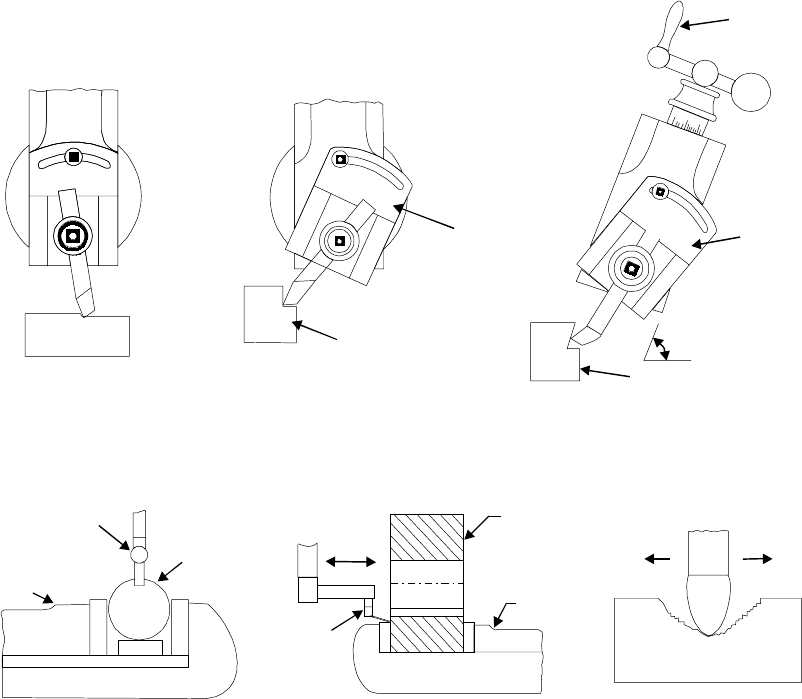
A shaper is a machine tool primarily designed to generate a flat surface by a single point
cutting tool. Besides this, it may also be used to perform many other operations. The different
operations, which a shaper can perform, are as follows:
1. Machining horizontal surface (Fig. 23.7)
2. Machining vertical surface (Fig. 23.8)
3. Machining angular surface (Fig. 23.9)
4. Slot cutting (Fig. 23.10)
5. Key ways cutting (Fig. 23.11)
6. Machining irregular surface (Fig. 23.12)
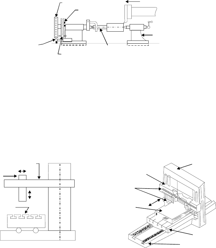
7. Machining splines and cutting gears (Fig. 23.13)
Apron
Job
Apron
Swivellin
g
an
g
le
of the vertical
slide
Work
Cuttin
g
slots and ke
y
wa
y
s.
Hand liver
Fig. 23.7 Machining horizontal Fig. 23.8 Machining vertical Fig. 23.9 Machining angular
vertical surface on shaper surface on shaper surface on shaper
Irre
g
ular machinin
g
Work
Slot cuttin
g
Tool
Vice
Tool
bit
Ke
y
wa
y
cuttin
g
Vice
Job
Fig. 23.10 Slot cutting Fig. 23.11 Keyway cutting Fig. 23.12 Machining irregular
on shaper on shaper surface on shaper
442 Introduction to Basic Manufacturing Processes and Workshop Technology
Machinin
g
splines and cuttin
g
g
ears
Index plate
Worm
g
ear
C
y
lindrical
job
Tail stock
Worm handle
Index
pin
Fig. 23.13 Machining splines and cutting gears on shaper
23.9 PLANER
Like a shaper, planer is used primarily to produce horizontal, vertical or inclined flat
surfaces by a single point cutting tool. But it is used for machining large and heavy work-
pieces that cannot be accommodated on the table of a shaper. In addition to machining large
work, the planer is frequently used to machine multiple small parts held in line on the platen.
Planer is mainly of two kinds namely open housing planer and double housing planer. The
principle parts of the open housing planer are shown in Fig 23.14(a). The principle parts of
the double housing planer are shown in Fig 23.14(b). The bigger job is fixed with help of the
grooves on the base of the planer and is accurately guided as it travels back and forth. Cutting
tools are held in tool heads of double housing planer and the work piece is clamped onto the
worktable as shown in Fig. 23.14(b). The worktable rides on the gin tool heads that can travel
Cross - rail
Tool
heads
Work
piece
Column
Work-table
Base
(b) Double Housin
g
Planer
C
o
l
u
m
n
Tool head
Table
Bed
Cross rail
(a) Open Side Planer
Fig. 23.14 Principle parts of double housing planer
from side to side i.e., in a direction at right angle to the direction of motion of the worktable.
Tool heads are mounted on a horizontal cross rail that can be moved up and down. Cutting
is achieved by applying the linear primary motion to the workpiece (motion X) and feeding
the tool at right angles to this motion (motion Y and Z). The primary motion of the worktable
is normally accomplished by a rack and pinion drive using a variable speed motor. As with
the shaper, the tool posts are mounted on clapper boxes to prevent interference between the
tools and work-piece on the return stroke and the feed motion is intermittent. The size of
Shaper, Planer and Slotter 443
a standard planer is specified by the size of the largest solid that can reciprocate under the
tool. In addition to this, some other parameters such as table size (length and width), type
of drive, number of speeds and feeds available, power input, weight of the machine, floor
space required etc. may be required to specify a planer completely.
23.10 WORKING PRINCIPAL OF PLANER
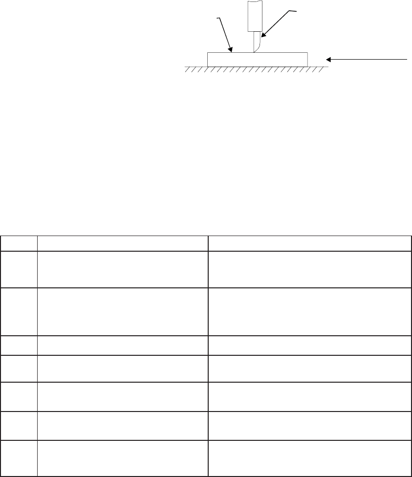
Fig. 23.15 depicts the working
principle of a planer. In a planer, the
work which is supported on the table
reciprocates past the stationary cutting
tool and the feed is imparted by the
lateral movement of the tool. The tool
is clamped in the tool holder and work
on the table. Like shaper, the planner
is equipped with clapper box to raise
the tool in idle stroke. The different
mechanisms used to give reciprocating
motion to the table are following-
1. Reversible motor drive
2. Open and cross belt drive
3. Hydraulic drive
23.11 DIFFERENCE BETWEEN SHAPER AND PLANER
The difference between shaper and planner is given in Table 23.1.
Table 23.1 Difference between Shaper and Planer
S.No. Shaper Planer
1 The work is held stationary and the In a planer, the tool is stationary and the
cutting tool on the ram is moved workpiece travels back and forth under
back and forth across the work the tool.
2 It is used for shaping much smaller A planer is meant for much larger jobs
jobs than can be undertaken on a shaper. Jobs
as large as 6 metre wide and twice as
long can be machined on a planer
3 A shaper is a light machine It is a heavy duty machine.
4 Shaper can employ light cuts and Planer can employ heavier cuts and
finer feed coarse feed,
5 A shaper uses one cutting tool Several tools can cut simultaneously on a
at a time planer
6 The shaper is driven using quick- The drive on the planer table is either by
return link mechanism gears or by hydraulic means
7 It is less rigid and less robust Because of better rigidity of planer, as
compared to that of a shaper, planer can
give more accuracy on machined surfaces.
Tool fixed in
tool head
Work piece
reciprocates
Motion of the
work piece
Fig. 23.15 Working principle of a planer
444 Introduction to Basic Manufacturing Processes and Workshop Technology
23.12 TYPES OF PLANERS
Planers may be classified in a number of ways, but according to general construction,
these are the following types:
1. Double housing planer
2. Open side planer
3. Pit planer
4. Edge or plate type planer
5. Divided table planer
23.13 SLOTTER
The slotter or slotting machine is also a reciprocating type of machine tool similar to a
shaper or a planer. It may be considered as a vertical shaper. The chief difference between
a shaper and a slotter is the direction of the cutting action. The machine operates in a
manner similar to the shaper, however, the tool moves vertically rather than in a horizontal
direction. The job is held stationary. The slotter has a vertical ram and a hand or power
operated rotary table.
23.14 PRINCIPLE PARTS OF A SLOTTER
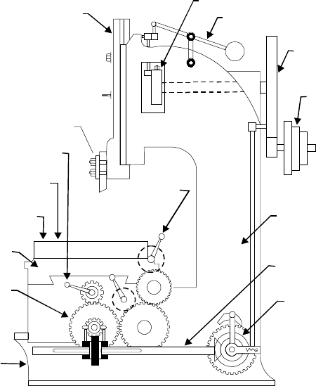
Fig. 23.16 shows a slotter and its various parts. The main parts of a slotter are discussed
as under:
Bed or Base
It is made up of cast iron. It supports column, tables, ram, driving mechanism etc. The
top of the bed carries horizontal ways along which the worktable can traverse.
Table
It holds the work piece and is adjustable in longitudinal and cross-wise directions. The
table can be rotated about its centre.
Hand wheels
They are provided for rotating the table and for longitudinal and cross traverse.
Column is the vertical member
They are made up of cast iron and it houses the driving mechanism. The vertical front face
of the column is accurately finished for providing ways along which the ram moves up and down.
Ram
It is provided to reciprocate vertically up and down. At its bottom, it carries the cutting
tool. It is similar to the ram of a shaper; but it is more massive and moves vertically, at right
angle to the worktable, instead of having the horizontal motion of a shaper:
Cross-slide
It can be moved parallel to the face of the column. The circular work-table is mounted
on the top of the cross-slide.
Shaper, Planer and Slotter 445
Ram
Crank disc
Lever
Bull
g
ear
Cone
pulle
y
Tool
Lon
g
itudinal
handle
Table
Cross feed
handle
Circular
feed
handle
Column
Cross
slide
Feed
g
ear
Base
Feed
shaft
Pawl
Fig. 23.16 Slotter and its various parts
23.15 OPERATIONS PERFORMED ON A SLOTTING MACHINE
A slotter is a very economical machine tool when used for certain classes of work given
as under.
(i) It is used for machining vertical surfaces
(ii) It is used angular or inclined surfaces
(iii) It is used It is used to cut slots, splines keyways for both internal and external jobs
such as machining internal and external gears,
(iv) It is used for works as machining concave, circular, semi-circular and convex surfaces
(v) It is used for shaping internal and external forms or profiles
(vi) It is used for machining of shapes which are difficult to produce on shaper
(vii) It is used for internal machining of blind holes
(viii) It is used for machining dies and punches, and
Since a slotter works slowly. It has less use in mass production work. It can be substituted
by the broaching machine.
23.16 QUESTIONS
1. Explain principal parts of a shaper by neat sketch.
2. How can you classify the shapers?
446 Introduction to Basic Manufacturing Processes and Workshop Technology
3. How can you specify a shaper?
4. Explain the principle of quick return motion mechanism of a shaper. What is need of this
mechanism?
5. Using neat sketches, describe the various operations that can be carried on shaping machines.
6. Explain various safety precautions associated with shaper.
7. Explain principal parts of a planer by neat sketches.
8. State the working principle of a planer.
9. Using neat sketch show the various parts of a planer.
10. Classify planers? Explain the universal planer.
11. Show by neat sketches various types of planer tools.
12. How table reversal is obtained in a planer?
13. Using neat sketches, describe the various operations that can be carried on planer.
14. Make neat sketch of a slotter. Explain its working with applications.
15. Differentiate between shaper, planer and slotter.
447
MILLING
24.1 INTRODUCTION
A milling machine is a machine tool that removes metal as the work is fed against a
rotating multipoint cutter. The milling cutter rotates at high speed and it removes metal at
a very fast rate with the help of multiple cutting edges. One or more number of cutters can
be mounted simultaneously on the arbor of milling machine. This is the reason that a milling
machine finds wide application in production work. Milling machine is used for machining flat
surfaces, contoured surfaces, surfaces of revolution, external and internal threads, and helical
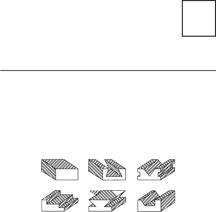
surfaces of various cross-sections. Typical components produced by a milling are given in Fig.
24.1. In many applications, due to its higher production rate and accuracy, milling machine
has even replaced shapers and slotters.
Fig. 24.1 Job surfaces generated by milling machine
24.2 PRINCIPLE OF MILLING
In milling machine, the metal is cut by means of a rotating cutter having multiple
cutting edges. For cutting operation, the workpiece is fed against the rotary cutter. As the
workpiece moves against the cutting edges of milling cutter, metal is removed in form chips
of trochoid shape. Machined surface is formed in one or more passes of the work. The work
to be machined is held in a vice, a rotary table, a three jaw chuck, an index head, between
centers, in a special fixture or bolted to machine table. The rotatory speed of the cutting tool
and the feed rate of the workpiece depend upon the type of material being machined.
24
CHAPTER
