Simmons C.H., Dennis E.M. Manual of Engineering Drawing
Подождите немного. Документ загружается.

10 Manual of Engineering Drawing
component drawing is dimensioned by algebraic
expressions understood by the computer. Each separate
size of component will be given its own part number.
When a particular part is required and called up, the
computer calculates sizes, draws the part to the correct
scale for the draughtsman to position where required
on the assembly drawing. This is a very useful facility
and only available through the introduction of CAD.
CAD always produces drawings finished to the same
high standard, and of a uniform quality and style. All
tracing costs are saved.
It will be seen from the above notes that CAD fits
in with many of the separate procedures necessary for
design and production, but it is vital that, before its
introduction, software must be available with proven
ability. Likewise, staff must receive training to extract
the maximum advantages and benefits.
Draughting in an organization which uses CAD
equipment does involve the question of security.
Technical product
documentation
Individual companies generally develop their own
systems largely depending on the type of work involved
and the size of the undertaking, e.g. original designs,
drawing revisions, modifications, repairs, new contracts,
enquiries and proposals.
These notes provide guidelines for new business
routines where both manual and computer based systems
are used. They refer to internal communication within
companies and between other organizations.
There are five short Standards dealing with the
handling of computer-based technical information
during the design process.
Part 1: BS EN ISO 11442–1. Security requirements.
This document details advice and precautions
regarding the system installation, power supply,
ventilation and cooling, magnetism and electrostatic
environment, also computer access.
Notes regarding service and maintenance, stand-by
equipment and back-up copies are given. Useful
comments relate to document authorization and
copyright.
Part 2: BS EN ISO 11442–2. Original documentation.
Definitions are provided for various types of
document used by industry in the Drawing Office.
Part 3: BS EN ISO 11442–3. Phases in the product
design process. Distribution of documents during each
phase is detailed.
Part 4: BS EN ISO 11442–4. Document management
and retrieval systems. This section deals with activities
in the design process and the handling of associated
documents, e.g. identification and classification of
administrative and technical documents. Provides
helpful advice in the management of documentation
in parallel with the phases of product development.
Assistance also given for drawing revisions, document
handling, classification and retrieval of data.
Ready-made ‘Turnkey’ data-processing systems are
available and can be adapted by specialist suppliers.
Part 5: BS EN ISO 11442–5. Documentation in the
conceptual design stage of the development phase.
Part 5 deals with documentation in the preparation
of a design specification, design proposals and solutions.
Problems can arise from power cuts of short and
extended time periods, and from spikes, or fluctuations
of power, due to other electrical equipment being
switched on. Stormy weather can cause surges and
static build ups. A reliable power source with a stable
supply is essential. Consideration should be given to
the provision of a backup supply, if in doubt. Service
and maintenance arrangements may require the issue
of external contracts, as computer downtime resulting
in lost production can prove expensive.
Computers generate heat, and wide variations in
environmental temperatures should be avoided. Air
conditioning in the complex may be necessary if cooling
is required and clean air cannot otherwise be guaranteed.
Part of the computer complex may need to be out of
bounds except to authorized personnel, to maintain an
acceptable environment. Care should be exercised in
the selection of floor coverings and furniture to protect
equipment from static electricity. Similarly tapes and
discs need to be shielded from stray magnetic fields.
Ensure that the CAD complex is kept locked and secure
when not in use at night and weekends.
An organization must develop a routine for storing
data on which company fortunes may depend. In the
even of power failure, work in progress may be lost. It
could also be lost due to operator error or computer
malfunction, fire, flood, vandalism, etc. Backup routines
must cover personal responsibility aspects, together
with frequency of copying, storage medium and
designated places of safety. Backup copies should not
be stored in the same buildings as the originals.
Programs used for operating and applying CAD
systems need to be checked at regular intervals to ensure
that intended methods are being kept in practice.
Computer aided designs and production information
could easily be copied and some countries do not have
legislation prohibiting unauthorized use. Documents
should therefore include a clause relating to copyright
where design information is transmitted, it is recom-
mended that the clause should appear before the text
and again at the end.
Many grades of staff are involved in the design
process; senior designers, detailers, checkers and
technical clerks all make a positive contribution. Each
member’s duties must be carefully defined with rules
applied, an authority given, so that each can only operate
within his or her agreed sphere of activity. By means
of passwords it is possible to access design information
Product development and computer aided design 11
at appropriate levels. Revision procedures will ensure
that modifications are only made at the correct point
by authorized designated staff. Quality assurance
systems require strict application of these methods.
Access into the computer
network
Every CAD installation requires access responsibilities
to be defined for the operating staff and the following
example relates to an educational establishment.
A typical College of Technology may consist of
three separate departments, each requiring to use a
common computer facility where a central processing
unit is installed. Each department is serviced using a
tree and branch system leading to the desks of staff
holding different levels of responsibility, and to student
outlets in classrooms, drawing offices and laboratories.
All members of staff and students need to gain access
to the computer freely, and in their own time, and be
able to store their work safely.
A Head of Department, however, may need to gain
access to the students’ work to monitor progress.
All members of the college staff would wish to have
a personal file and keep confidential records. A lecturer
must be free to allocate space to students in several
classes, so he or she will open subdirectories as
necessary and possibly delete work at the completion
of a course.
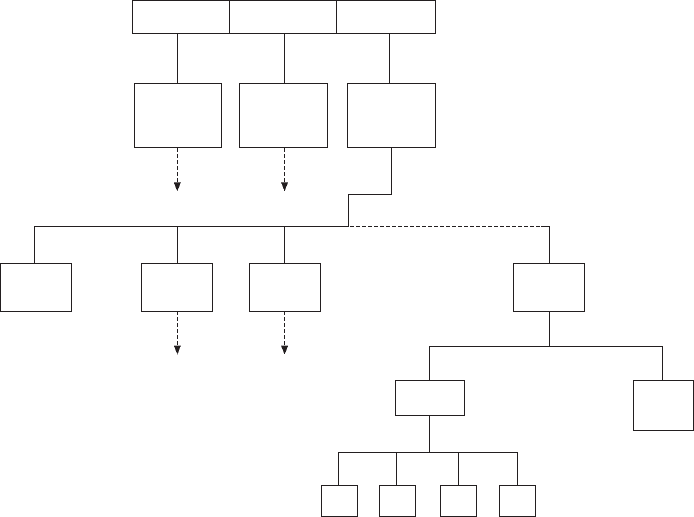
Figure 2.2 shows a directory structure where access
can only be made into the system provided the keyboard
operator logs in a personal identity number. Each
member of staff will be assigned two directories:
(a) a top level directory (TLD);
(b) a personal directory (PD).
The TLD is the attach point for the user into the system.
The lecturer is free to ‘open subdirectories for students’
work and each student’s file will be protected from the
rest of the class. The Head of Department has access
to a lecturer’s TLD and through to a student’s file.
The above system can be adapted for any graded
organization where controlled access and protection
for records is desirable.
Quality assurance
BS EN ISO 9000 series relates to quality systems and
is produced in several sections. The principles of quality
assurance embrace all activities and functions concerned
with the attainment of quality. BSI Quality Management
Handbook QMH 100 is essential reading.
Having purchased quality CAD equipment, the
products which the company propose to manufacture
need to be designed and developed from conception
following an agreed quality assurance working
procedure practised by all employees throughout the
organization. QA systems are usually accredited and
certified by a third party such as a professional institution
or association.
An organization should be able to show that all
drawings, documentation and necessary calculations
Fig. 2.2 Directory tree for controlled access to database
Mechanical Electrical Civil System database
Mechanical
top level
directory
Electrical
top level
directory
Civil
top level
directory
Attach point for
each Head of
Department
Civil
Head PD
Personal directory
for Head of Civil
Engineering Dept.
Civil
1 TLD
Civil
2 TLD
Civil
4 TLD
Sub dir.
S1 S2 S3 S4
Student project files
Attach point for
lecturer 4 in
Civil Dept.
Civil
4 PD
Personal directory
for lecturer 4
in Civil Dept.
12 Manual of Engineering Drawing
relating to the design, are vigorously checked and
approved by management. The stage by stage
development of the product will follow an agreed work
plan with checks, inspections and correction procedures.
Similar plans will cover the manufacturing stages from
raw material checks to the tested product. Good
communication between all of the participants is
essential to ensure that the product meets its specification
and the customer’s exact requirements.
A company which can demonstrate superior technical
skill and expertise has a considerable asset which can
be used to advantage in marketing. Proven excellence
invariably increases pride and well-being in company
employees.
Computing developments have made a rapid and
immense impact on industry and commerce and as the
degree of complexity has also increased, then training
facilities have expanded accordingly. As a source of
information and communication, the Technical Press
and the Internet play a very important part. Journals
from professional institutions offer impartial news,
advice and guidance, opinions, and new product details.
Manufacturers and the larger suppliers of CAD equip-
ment have set up centres around the country where
exhibitions and demonstrations are organized. Higher
education establishments, private organizations and
dealerships also give specialist courses for the benefit
of students and users.
The mainstream engineering software programs have
been written and developed in the United States and
the UK. To perform complex tasks, additional pro-
gramming may need to be seamlessly integrated so
that they work in harmony as a unit.
There are literally hundreds of specialist applications
available. Banks, Building Societies, Airlines, all have
their own systems and via the Internet, can freely
communicate with each other. This fact has also given
rise to another branch of industrial development, i.e.
security.
Screen sizes have increased in size and the availability
of the flat screen has reduced the size of workspace
required by users.
The provision of multi-layers provides a very useful
method of working on CAD. Imagine transparent sheets
placed on top of each other, which may be shuffled
and rearranged so that you can draw on the top. Each
of the layers underneath in the pile can be turned on or
off, they may be given identification colours and selected
parts of drawings moved from layer to layer if required.
Assume that we want to draw plans for a house. Layer
1 could be used to draw a plan view of the building
plot. Layout work is often easier if graph paper is
used. On layer 2 we make our own construction grid,
which is transparent graph paper with squares to any
convenient scale of our choice. Using this grid under
layer 3 we design a suitable ground floor layout.
Copying the position of the outside walls from layer 3
and modified as required could start layer 4 showing
the first floor layout. When all of the required plans
and elevations are constructed, they can be repositioned
on a drawing arrangement. If necessary, the site layout
reduced to a smaller scale. When completed, the
construction grid may be deleted. Tracing facilities
and the ability to print layers together or apart are a
valuable draughting asset.
The physical equipment components of a computer
system are known as the hardware. The programs and
data used on the computer are defined as the software.
Another advantage of CAD is its ability to store
line systems and other entities, which are frequently
used on drawings. For example, software containing
symbols to British, European and other International
Standards is freely available for most engineering
applications. The draughtsman can also create libraries
of regularly used parts.
For repetitive use on a drawing, a typical item may
be retrieved and positioned in seconds, also oriented
at any angle to suit particular circumstances.
As a drawing aid, every CAD program must provide
basic geometric features, permitting the operator to
blend lines and arcs etc. It is necessary in engineering
drawing to be able to determine points of tangency
between straight lines and curves and between curves
of different radii.
Productivity is much improved by a program enabling
you to easily draw polygons, ellipses, multiple parallel
lines and multiple parallel curves. The speed of machine
drawing is increased by the use of automatic fillets
and chamfers. Layout work benefits when use is made
of construction grids and the computer’s ability to ‘snap’
automatically to particular geometric points and features,
will speed the accurate positioning of line work. Copy,
rotate and mirror facilities give assistance when drawing
symmetrical parts. Automatic cross-hatching within
closed boundaries is useful in the construction of
sectional views and when indicating adjacent parts and
different materials. Many changes of hatch patterns
are supplied with CAD programs. Filling areas in
various colours is a requirement in artwork.
The ability to zoom in and out is an asset when
drawing to scale. It is possible to work on fine detail
in an assembly and then zoom out to observe the result
in context.
CAD information is stored in digital form and hence,
irrespective of the size of the final printed drawing; it
is possible to accurately dimension components auto-
matically.
Different ‘type-set’ and alternative style fonts are
Chapter 3
CAD organization and
applications

14 Manual of Engineering Drawing
always supplied with CAD programs. If a special font
is required to match an existing style then specialist
vendors can supply. Alphabets in different languages
present no problem. Quite clearly the physically largest
affordable screen has many advantages. If the
draughtsman is also involved with desktop publishing,
it is ideal to be able to work on a screen that displays
two A4 paper sheets side by side so that ‘what you see
is what you get’. The screen should give high resolution,
necessary to provide an image that is flicker free. The
quality of the display will have a big contribution to
make in the avoidance of fatigue and eyestrain. First-
hand practical experience and a demonstration is
important here for an ideal solution.
Plotting and printing equipment will vary according
to drawing office requirements. It is true, however,
that many CAD installations are judged by the quality
of their plotted drawings. It is necessary to also have
a demonstration and this will ensure that an excellent
CAD system will have an output to do it justice.
A wide variety of plotters are available for repro-
ductions from A4 to AO in size, and in a quality suitable
for production work or the most prestigious pre-
sentations.
Probably the best-known software in the Drawing
Office is that from AutoCAD, who build products that
conform to the most widely used DWG format
permitting the transfer of information between networks.
In the 1970s, 2D drawing packages were introduced
with the ability to slowly draw lines, circles and text.
Rapid developments have taken place since with a vast
increase in computing power. The computer industry
has expanded, progressed and now produces software
for an ever increasing number of engineering
applications. Computing power is vital for the operation
of highly sophisticated research projects, advanced
design and modelling programs. Communication
developments have had a profound effect regarding
the methods that we use for our current solutions. We
have the capability to transmit files of drawings and
notes from the computer screen for use by collaborative
partners, and the Internet can transmit information
around the world in seconds.
Solid models suitably animated can also be viewed
in 3D to clarify detail and this can be a considerable
asset where perhaps there is a change of language.
User manuals for domestic equipment are commonly
drawn in solid modelling programs to illustrate
sequences of assembly and improve clarity for non-
technical customers.
A very important part of work in the drawing office
is dealing and handling revisions and modifications. It
is possible to link drawings so that if you update the
master, linked drawings are updated automatically.
Modifications use quite a large proportion of drawing
office time.
Immediate transmission to all members of an
associated group has considerable advantages. Examples
here are recall notices for car owners and faulty items
in domestic appliances.
There are many examples where various component
parts are manufactured in different countries and brought
together for assembly and testing. The aircraft industry
is a typical case.
Drawings are reproduced in many sizes and small
items present little difficulty with zoom facilities. Views
drawn to different scales and a variety of orientations
can be arranged on the same drawing print as an aid to
comprehension. Windows giving an overall view of
your drawing for fast zooming and panning are also of
value.
Autodesk, Inc. is the world’s leading producer of
CAD visualization and animation software for personal
computers and workstations. Courses in AutoCAD
r
programs are taught in many educational establishments,
and since 1987 certified national courses of study by
the City and Guilds of London Institute have been
conducted throughout the country. Authorized training
centres cater for the needs of local industry and for
those who wish to develop their CAD skills further.
Autodesk
r
has been at the forefront of applying
standards within the computer aided design environ-
ment.
The main professional program AutoCAD 2002 is
very much a non-specific or generic CAD tool and
many applications are available to the basic graphics
package, which enhance its suitability for a particular
discipline.
Full specifications for these products can be found
on the Web by visiting http://www/autodesk.co.uk.
The AutoCAD Applications Handbook, which is a
CAD User Publication, lists many hundreds of software
packages which can be used to maximize productivity
in association with AutoCAD.
AutoCAD 2002 is the technology platform, which
facilitates communication and collaboration between
team members involved in design projects, also, clients,
suppliers and vendors.
Typical projects could involve solutions involving
building design, communication, and government
utilities land development and manufacturing industries.
It can also download design data from the Internet,
allow you to automatically publish design data on the
Web, host online meetings, drag and drop content from
manufacturers websites into your drawings and much
more. It delivers higher levels of productivity through
unmatched performance and simplicity.
Work on multiple drawings can be undertaken.
As an example of the flexibility and range of typical
projects about 40 typical case histories are given on
the Company website.
Below are listed some products either from Autodesk
or others which integrate directly with Autodesk
products. This ensures compatibility throughout the
design process, from conception, through design, testing
and manufacturing.
Autodesk, the Autodesk logo, and AutoCAD are registered
trademarks of Autodesk, Inc. in the USA and/or other countries.
CAD organization and applications 15
AutoCAD Mechanical is a purpose built 2D mechanical
design solution providing an ideal platform for
production drawing and detailing.
Additional useful add-on programs are available for
analysis and manufacturing solutions from MSC and
Pathtrace, as well as document management solutions
from Cyco.
Autodesk Inventor Series. For integrated 2D design
and detailing, 3D assembly, parametric design and the
capability to produce complex 3D surface models,
Inventor Series 5 gives you the following compatible
programs.
The series includes Autodesk Inventor 5.3,
Autodesk® Mechanical Desktop 6, AutoCAD
Mechanical 6 and AutoCAD 2002. You get all of
these technologies in one easy-to-use package giving
you flexibility to use what you want when you want.
No need to choose between 2D and 3D.
Suitable for Sheet Metal Design, 3D Modelling and
Automatic Detailing, DWG file compatibility and
extensive parts library.
This is a combination package of Autodesk
Mechanical Desktop and Autodesk Inventor software.
Architectural Desktop 2004 is a program optimized
for building design using AutoCAD 2002. A flexible
display system used to manage and create plans,
elevations, sections and 3D views. Designed with an
automatic scheduling feature and links to VIZ4.
Building design information can be shared with the
rest of the project team. Designs in 3D assist in co-
ordination and approval with clients.
Autodesk VIZ 4 is a software program for design
conceptualization and visualization, which combines
modelling, texturing, and rendering features to create
stunning visual presentations and walkthroughs.
The program quickly and simply generates 3D
models and has a comprehensive library of materials
and textures.
VIZ 4 will link to AutoCAD 2002 and the Design
2000 family of products: Architectural Desktop, Land
Development Desktop and Mechanical Desktop.
Piranesi is a three dimensional paint program, which
enables architects, artists and designers to produce high
quality stylized artwork from 3D models. The initial
3D model is produced as normal in an existing CAD
and/or visualization system. Unlike conventional 2D
paint programs, Piranesi paint tools enable you to use
colours, tints and textures (a brick pattern say) straight
onto selected parts of an image, without overpainting
other objects. It can be used by itself to produce artwork
from AutoCAD models directly, but it really comes
into its own when used as a post-processor for VIZ.
NavisWorks is a software program which can navigate
and view models of extreme size and allow all design
data to be brought together into one. This facility enables
faults to be detected early during project development
rather than on site after construction begins.
The program automatically locates and highlights
areas of the model where parts interfere or clash with
each other. This ‘Clash Detective’ function can quickly
analyse the model and then dim everything except the
clash detail. Faults are easily communicated to others
in the design team.
A wide range of companies, contractors and designers
can work on a single project without having to get
together in the same place at the same time. This
obviously reduces hidden project costs.
NavisWorks files are generated directly from within
AutoCAD.
An optional feature provides easy to apply, ‘near
real’ textured materials for improved visualization.
Autodesk Raster Design 3. Scanned paper drawings,
aerial photos, satellite imagery and maps can be
integrated into the computer system and edited raster
data converted to vector. Vectorization Tools with Smart
Correct technology create lines, polylines, circles, arcs,
text and rectangles. Intersecting raster geometry can
be preserved when raster entities are moved or erased.
The program can read and write georeferenced images
to and from the Web. Raster design can help you gain
more value from existing archive drawings and possibly
avoid time-consuming redrafts.
AutoCAD LT 2004 contains powerful 2D and basic
3D geometry creation, editing, display and plotting
options and uses the AutoCAD DWG file format so
interchange of existing files presents no problem if the
program is upgraded to the main professional program
AutoCAD 2002.
For many CAD users AutoCAD is too
comprehensive, advanced and expensive for their needs
and in cases where the draughtsman is mainly
responsible for layout work and design work, which
does not involve sophisticated modelling and rendering,
then this program is well worth considering. The current
price is less than £500.
The ability to draw and to use the drawing, or part
of the drawing, in a word processor document will be
much appreciated. The software has a familiar feel as
it uses the Windows interface, so if you have used
pull-down menus, dialogue boxes and the drag and
drop simplicity of Windows; you will soon master the
basics since the Help feature provides an on-line guided
learning assistance tour. The 2D draughting content is
identical with that of the early Release 12 of AutoCAD.
The toolbox and toolbar can easily be customized and
arranged to suit your own preferences and style of
working. The system will also accommodate a selection
of symbol files.
AutoSketch. A typical starter CAD program is
AutoSketch which is easy both to learn and to use. It
is a low cost package, ideal for anyone who wants to
use a computer to sketch or draw without investing in
a full-scale system.
16 Manual of Engineering Drawing
Drawings are created by choosing drawing and
editing commands from pull down menus. Drawings,
patterns and fonts are represented by simple symbols,
or icons. You can draw on multiple layers and look at
them in any combination. Repetitive drawing is
eliminated: you can use previously created drawings to
build libraries of frequently used symbols, saving time.
Having drawn an object you can move, copy, rotate,
mirror, stretch and erase it until it matches your needs.
You can group components together and treat them as
one, and break them apart for editing. The UNDO
command permits drawing changes, or to change back
again, use REDO. Expanded memory support allows
you to work with large drawings. Part clipping allows
you to select items from existing drawing files and use
them in others. Text and notes can easily be added or
edited on the drawing using a variety of fonts. The
drawing features include line options, arcs, ellipses,
circles, points, pattern fill areas, spline curves and
polylines with variable line width. Automatic fillets
and chamfers are possible, and the program also offers
zoom and pan facilities.
The program allows you to export drawings directly
into AutoCAD, and a wide selection of desktop
publishing packages.
Computer and software
purchase
It is strongly recommended that before any purchases
are made, the client seeks advice from a recognized
and authorized dealer, as they would be able to check
that the equipment can perform the tasks you expect
in your style of working. Practical demonstrations are
very necessary before issuing orders. CAD equipment
is a tool and there are possibly many ways of doing
the same job. In this computer age it may well be that
an experienced dealer can indicate a better and more
productive way.
Your supplier would also give you a written
specification for computers and software indicating
any other relevant equipment required for protection
and safe operation.
Project development
The reader will appreciate that the design of, for
example, a large construction project from its con-
ception, will involve technical input from architects
and engineering designers in a wide variety of associated
disciplines. It is vital that all contributors to the overall
scheme talk the same language and that only compatible
computer software packages are in use for the separate
areas of work. In addition, the management contractor
must have access to the designs as work is in progress.
Before the age of CAD it was the practice to have
countless meetings in order to co-ordinate progress.
Design obviously continues in steps and in planning
and construction work problems arise, and designers
need to be in a position to make modifications to
overcome them, before progressing to the next phase.
A typical case study illustrating the activity associated
with this type of work is the construction of the new
Civil Aviation Authority ‘en-route’ centre, built at
Southampton. This prestige building and installation
controls all the air traffic passing through Britain’s
airspace and houses controllers operating banks of
electronic and computer equipment where only an
efficiency of 100% is acceptable. The building services
engineer must ensure that the environment to keep
both controllers and equipment comfortable is
maintained 24 hours a day, seven days a week.
Due to the extensive use of computers at the centre,
a huge amount of electrical, heating, ventilating and
air conditioning plant needed to be installed. Different
specialist contractors were responsible for these services
under the stewardship of the management contractor.
The fast track nature of the design and construction,
required an extensive application of CAD, where
individual contractors responsible for electrical,
mechanical and ducting work, were ‘net-worked’ on
site, and could refer to CAD data from each other.
At this development, it was accepted by contractors
that for some drawings it was practical to work in
three dimensions to make it easier, for example, to
ensure clearances between piping and ductwork in the
more cramped areas. Layout drawings in 3D permitted
engineers to demonstrate clearly to other parties where,
for example, electrical cables and conduits were likely
to plough straight through heating and ventilation ducts.
Potential problems were solved on screen rather than
emerging during construction. In addition, adequate
access for maintenance purposes and replacement of
equipment could be confirmed. The draughtsman can
check designs by altering the angles from which
arrangements are viewed on screen.
In the design of many heavy engineering plant layouts
it is often the practice to build a scale model of the
plant as design work progresses. The function of the
model is to keep a running check on the feasibility of
the installation. Obvious improvements can then be
incorporated.
Constructions of chemical plants and oil refineries
are typical examples. After completion of the project,
models may be used for publicity purposes and to
assist in the education of technicians who operate and
service the equipment. Three dimensional modelling
has many other applications in the film and entertain-
ment industry and drawings in 3D can materially assist
in comprehension.
When many workstations have to be installed for a
design team, it is vital to agree on working methods.
Recommendations for useful Standards in Construction
Drawing Practice are detailed in Chapter 27.
Agreement is necessary on the organization of many
aspects of work and in CAD, these include the use of
layers, the groupings of the various sections of
CAD organization and applications 17
construction designs, use of colours so that similar
ductwork appears on the screen in the same shade,
procedures for the transfer of data between several
drawing offices, methods of structuring data for
archiving and to help future retrieval. The quality of
all drawing work needs to be uniform and conform to
BS 8888 for a complete understanding and to avoid
ambiguity. It is essential that all contributors work as
a team and in harmony if planning deadlines are to be
kept, as obviously, delays in one area of construction
can hold up another contractors work, and may result
in financial loss.
The designs for services and installations originate
from specifications and schematic layouts, supplied
by Consulting Engineers, acting on behalf of the Clients
or Agents.
For layout work a typical draughting package which
covers all aspects of services, such as electrical, lighting,
communication, alarms, ductwork, sanitary and
mechanical plant, is desirable and time saving. Standard
symbols can be inserted on their apropriate drawing
layer, rotated automatically to align with a wall or
ceiling grid and automatically scaled so that they are
plotted at the correct scale. These settings can also be
customized to enable you to predefine commonly used
layers and sizes.
The Building Services Library supplied by
HEVACOMP,
109 Regents Park Road,
London
NW1 8UR
is a typical package which covers these requirements
and permits you to store up to 600 of your own symbols
using tablet or pull down menus. The package will
assist in the creation of working drawings and in the
detailing of, for example, sections of ductwork, the
program will prompt for the dimensions, elevation and
layer; subsequent sections of ductwork are then able
to attach automatically, matching the layer and size.
Parametric routines are also used to efficiently design
a wide variety of bends, tees, branches and transition
pieces for all types of square, rectangular, circular and
oval ductwork.
Schedules of fittings need to be created with essential
information and if necessary interfaced with other
database or spreadsheet programs, in order to prepare
bills of materials.
Electrical wiring systems for lighting and services
must be designed in accordance with I.E.E. Wiring
Regulations and programs are available to provide the
essential requirements of both the electrical designer
and contractor.
The ELEC program from HEVACOMP can be used
to calculate all cable, cpc and fuse sizes, as well as
voltage drops, earth fault loop impedances, and short
circuit currents. Schematic diagrams are easily prepared
up to AO in size, showing load descriptions, protective
device and cable sizes as well as sub-main details.
Reporting facilities include:
Board and way data,
Cable sizes and voltage drops,
Short circuit currents and disconnection times,
Discrimination charts,
Input data,
Calculation file data,
Load current summary,
Voltage drop summary,
Equipment schedules.
Size of computer
As a rough guide to selection, the larger the drawing
and degree of complexity, the more important is the
performance and power of the computer and its operator.
If a drawing contains large areas which are
crosshatched or shaded, for example, it is important to
be able to redraw illustrations quickly to prevent time
wasting.
It is easy to obtain demonstrations of computer power
and this is recommended. When selecting software
products required to operate with each other, it is
necessary to check compatibility; your dealer should
advise.
You will appreciate from the applications mentioned
above that associated specialist software is being
developed all the time both here and in the US. The
one certain aspect is that future trends will use
applications needing greater amounts of computer
memory, so the chosen system must be expandable.
Consideration must also be given to the question of
storing drawings, filing systems and information
retrieval.
Given the rapid progress and changes in the Drawing
Office during the last ten years the only prediction one
can make is that the role of the draughtsman, far from
diminishing, is more important than ever.
Parametric design
It is a common drawing office practice, where a range
of parts are similar, to produce a single drawing with
a table of dimensions for the features of each separate
component. The user will then need to sort out the
appropriate sizes of each detail relating to the part
required. The drawing itself being representative of a
number of similar parts cannot be drawn true to scale
for them all.
A study of Fig. 3.1 will show a special screw, which
has a family of parts. It is defined on a single drawing
where the main dimensions are expressed algebraically
as ratios of the shank diameter of the screw and other
relevant parametric values. For a given thread size and
screw length the CAD system is able to produce a
true-to-size drawing of any individual screw listed.
This drawing may then be used as part of an assembly
drawing, or fully dimensioned and suitable for
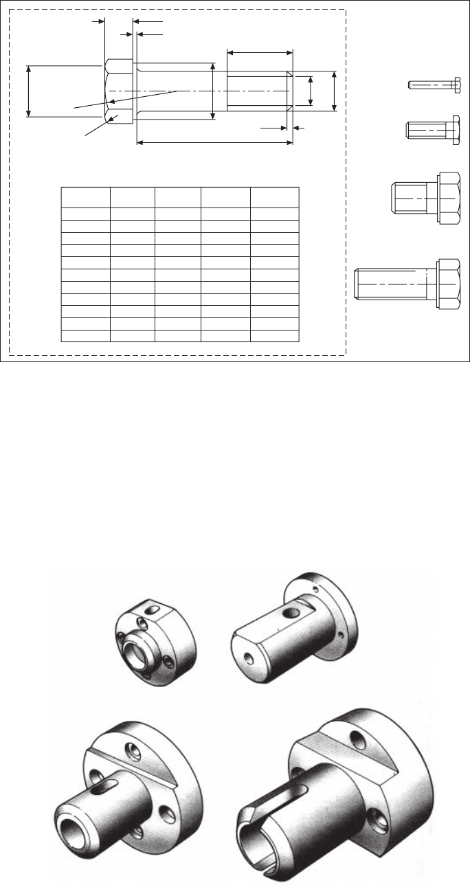
18 Manual of Engineering Drawing
manufacturing purposes. Four typical screws are
indicated at the right-hand side of the illustration. It is
always a positive advantage in design work to appreciate
true sizes and use them in layouts.
Components such as bolts, nuts, washers, fasteners,
spindles, seals, etc., fall naturally into families where
similar geometric features are present. The parametric
capability of the CAD system can be used to
considerably improve productivity in this area of
drawing office work.
It is not an uncommon practice in product
development to modify existing standard components
if possible and use them as the basis for new ones.
Notice the visible connection between the features of
the four components illustrated in Fig. 3.2. This is a
further example of parametrication where the principles
of variational geometry have been applied.
The family of parts is constructed from a large and
small cylinder with different diameters, lengths and
central bore sizes. A chamfer at the left-hand end, a
7×D/10
D/25
3/4xS/EQ1
3/4xS/EQ1
(S/EQ1) × (3–6QRT(5))/4
L
D/10
D-1.2×P
D
L – A
LET EQ1 = cos (30)
PAR F1L 20
S
M4 × 25
M8 × 25
M16 × 25
M16 × 45
D5AP
M3 3 55/10 15/10 5/10
M4 4 7 21/10 7/10
M5 5 8 24/10 8/10
M6 6 10 3 1
M8 8 13 4 125/100
M10 10 17 45/10 15/10
M12 12 19 53/10 175/100
M14 14 22 6 2
M16 16 24 6 2
M18 18 27 75/10 25/10
M20 20 30 75/10 25/10
Fig. 3.1
Fig. 3.2

CAD organization and applications 19
vertical hole extending into a slot and a flat surface at
the top are added details.
Parametric systems handle the full range of linear
and angular dimensions including degrees and minutes.
The computer will also calculate maximum and
minimum limits of size from specified tolerance values.
Dimensions can be defined numerically or as algebraic
expressions. You can avoid the need to dimension every
fillet radius for example by setting a default value for
radii. This means that unless a specific value is stated
for a particular radius on a part that it will automatically
be drawn at a previously agreed size. Where many
radii are present, as in the case of casting work, this
feature is a considerable aid to drawing office
productivity. A number of such defaults can be entered,
to cover a variety of applications.
Areas of detail within a drawing, which are not
required to be parametricated can be excluded by
enclosing them in a group line and this avoids the
need to dimension every detail. The geometry contained
in the enclosed group may remain static or magnified
when the part is parametricated.
A further advantage of expressing dimensional values
in algebraic form allows the designer to simulate the
movement of mechanisms and produce loci drawings
of specific points. It is essential in the design of
mechanisms to appreciate the path taken by every point,
which moves.
Sheet metalwork
application
The design of components to be manufactured from
folded sheet metal is a field in which CAD systems
can offer great assistance.
In the case of the bracket shown in Fig. 3.3 it would
first be necessary to establish the overall dimensions
of the part.
the type of metal used. Metals behave quite differently
when bent and the CAD system can be programmed to
calculate an appropriate bend allowance. After stamping
the bracket can be refolded with suitably radiused bends.
In this particular case the dimensions of the stamping
are also needed for the design of the press tool set.
The design can be checked for material accuracy,
weight, volume, and so on, before being committed to
manufacture.
Computerized programs can be produced to operate
lathes, mills, flame cutting machines, etc. and many
other items of equipment in the manufacturing process.
Models may be constructed in several different ways,
including: geometric modelling, meshed surfaces,
sweeps, volumes of revolution and ruled surfaces. Each
of these is summarized below.
Geometric modellers build models from geometric
solids, which have the attribute that mathematical
formulae exactly define any point in 3D space occupied
by these solids. Shapes include planes, cylinders,
spheres, cones, toroids, etc. These shapes are combined
using Boolean operations to produce the component.
The Boolean operations produce a 3D model by a
combination of the following methods:
(a) resulting from the union of any two 3D objects
or shapes;
(b) resulting from the difference between any two
3D objects or shapes;
(c) resulting from the volume that is common to any
two 3D objects or shapes.
This approach is very successful for modelling machined
components but cannot handle anything that might be
described as having a freeform shape.
Meshed surfaces. X, Y and Z co-ordinates are either
calculated, transferred from 2D drawing views, or
measured to provide basic modelling input. The
modeller will then generate a 3D meshed surface joining
up all the specified points. In order to build up a well-
defined surface, the modeller interpolates between points
defined in the user input in order to develop a fine
enough mesh to show a smooth change in cross-section.
This method can be used to produce the freeform shapes
used in, for example, styling household appliances.
Fig. 3.3
The second step would be to imagine that the bracket
is folded back gradually as indicated in Fig. 3.4 into
the flat sheet form. This shape would then be stamped
from metal strip in a power press.
The dimensions of the flat pattern have to make
allowance for the bend radius, the metal thickness and
Fig. 3.4