Selection of Generator for SHP (Draft), AHEC Roorkee, India
Подождите немного. Документ загружается.


AHEC/MNRE/SHPStandards/GuidelinesforselectionofHydroGeneratorforSHPPage38
exciter, not less then
12. Ceiling voltage of exciter when connected 2
to the generator field and with rated
exciter current delivered (80 degree C)
8.
Line charging capacity of the generator, 7,000 kVA
when charging a transmission line, at rated
speed and voltage, without being completely
self excited or unstable not less then KVA
9.
Maximum ambient air temperature 46
o
C
degrees centigrade
C. MECHANICAL CHARACTERISTICS
1. Flywheel effect (WR
2
) of rotating Normal
parts of the generator and exciter
2. Direction of rotation To match turbine
3. Maximum runway speed r.p.m. To match turbine
4.
Maximum temperature of inlet cooling 36
o
C
water for air cooling system
5.
Design mechanically to withstand 9000 kW
Continuously. Without exceeding the
specified normal operating stress,
a load of kW (1.0 pf)
6.
Design mechanically to withstand 9900 kW
temporary overloads, with stress not
exceeding one – half the yield point
corresponding to turbine output of
not less then (provided that the duration
of such overload is not sufficient to
cause injurious heating) kW.
7.
Designed for operation with a turbine 9250 kW at 0.9 gate
having the following rated output kW. opening the rated head
D. INSULATION AND TEMPERATURE RISE
a. Insulation shall be provided as follows:
(i) Stator Winding Material corresponding to class F
(ii) Rotor Winding Material corresponding to class F
b. The generator shall be capable of delivering rated output at any voltage and
frequency in the operating range at rated power factor without exceeding the
following values of temperature rise over ambient temp. Cooling air entering the
generator at not more than 40
0
C (Cooling water maximum temperature 36
0
C).
(i) Stator Winding 70
o
C

AHEC/MNRE/SHPStandards/GuidelinesforselectionofHydroGeneratorforSHPPage39
(ii) Rotor Winding 70
o
C
(iii) Stator core 75
0
C
c. The maximum temperature rise when the generator is delivering maximum output
corresponding to continuous overload capacity for conditions rated above shall
not exceed 90
o
C for both for stator and rotor winding respectively. Temperature
rise shall be guaranteed in the tender and shall be measured on site in accordance
with IEC 340 or relevant IS.
E. SPEED RISE AND RUNAWAY SPEED
The moment of Inertia of the generator together with the moment of inertia of the turbine
shall be such that the maximum momentary speed rise under Governor Control on full
load rejection shall not exceed 45% of rated speed for the grid connected generator as
station power is supplied from main generator and adverse effect of this speed rise on
motor driven station auxiliaries is not desirable. Additional flywheel required shall be
built in the rotor. Separate flywheel shall not be permitted.
The maximum runaway speed shall be stated and guaranteed by the supplier. All rotating
parts and bearings shall be capable of withstanding the forces and stresses occurring
during runaway speed for at least 30 minutes without any damage to any part. The guide
bearing and guide cum thrust bearing shall be capable to withstand runaway speed for 30
minutes without supply of cooling water and continuously with cooling water without
abnormal increase of vibrations and temperature.
AHEC/MNRE/SHPStandards/GuidelinesforselectionofHydroGeneratorforSHPPage40
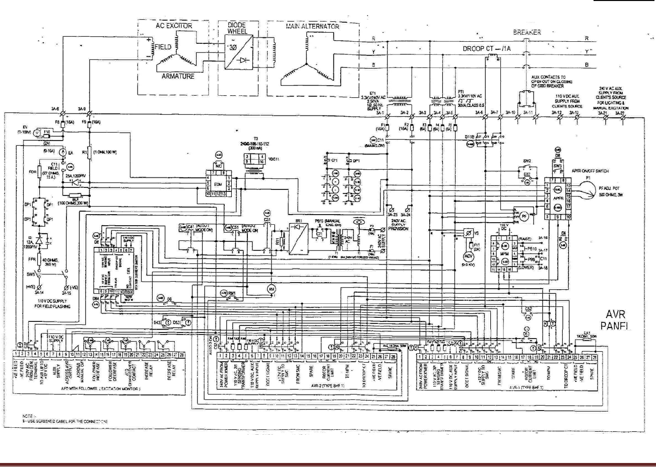
Annexure-4
Brushless Excitation System for 1.5 MW, 3.3 kV, 750 RPM, 50 Hz, 0.8 PF, 8 poles Generators (Pacha Project)
AHEC/MNRE/SHPStandards/GuidelinesforselectionofHydroGeneratorforSHPPage41
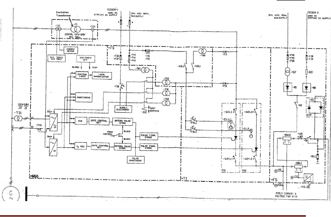
Annexure-5
Static Excitation System - Block Diagram for 9 MW, 11 kV, 0.9 PF, 125 RPM Generators