Schweitzer P.A. Fundamentals of corrosion. Mechanisms, causes, and preventative methods
Подождите немного. Документ загружается.

Cathodic Protection 299
becomes the cathode and is protected, while the anode is destroyed progres-
sively and is called a sacricial anode.
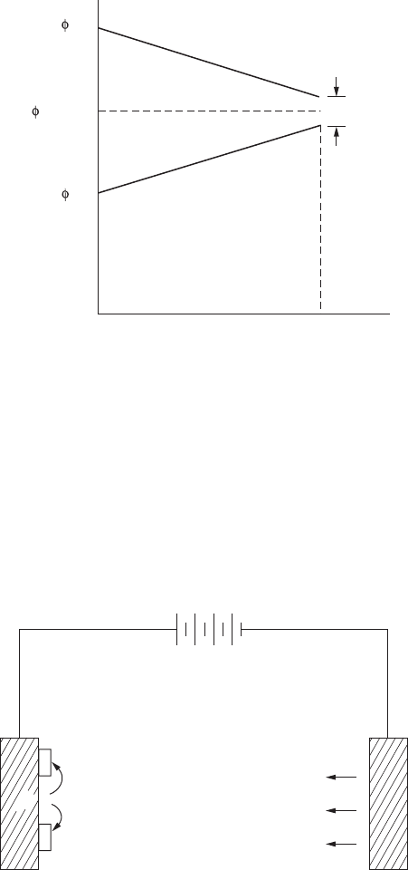
The second method is to impress a direct current between an inert anode and
the structure. The structure receives the excess of electrons, which protects it.
About 1910 to 1912, the rst application of cathodic protection by means of an
impressed electric current was undertaken in the United States and England.
Since that time, the general use of cathodic protection has been widespread.
Current
Zn
Potential
I
(max)
I
(max)
R
e
Cu
(corros)
FigurE 9.1
Polarization of copper-zinc cell.
Auxiliary
anode
Corroding
metal
+
+
+
B
–
–
Electrolyte
FigurE 9.2
Cathodic protection using impressed current on a local action cell.

300 Fundamentals of Corrosion
There are thousands of miles of buried pipelines and cables that are protected
in this manner. This form of protection is also used for the protection of water
tanks, submarines, canal gates, marine piping, condensers, and chemical
equipment.
9.2.1 Sacrificial anodes
It is possible, by the selection of an anode constructed of a metal more active
in the galvanic series than the metal to be protected, to eliminate the need for
an external DC current. A galvanic cell will be established with the current
direction exactly as described using an impressed electric current. These
sacricial anodes are usually composed of magnesium or magnesium-based
alloys. Occasionally, zinc or aluminum has been used. Because these anodes
are essentially sources of portable electrical energy, they are particularly use-
ful in areas where electric power is not available, or where it is uneconomical
or impractical to install power lines for this purpose.
Most sacricial anodes in use in the United States are of magnesium con-
struction. Approximately 10 million pounds of magnesium is annually used
for this purpose. The open-circuit potential difference between magnesium
and steel is about 1 V. This means that one anode can protect only a limited
length of pipeline. However, this low voltage can have an advantage over
higher impressed voltages in that the danger of overprotection to some por-
tions of the structure is less; and because the total current per anode is limited,
the danger of stray-current damage to adjoining metal structures is reduced.
Magnesium anode rods have also been placed in steel hot-water tanks to
increase the life of these tanks. The greatest degree of protection is afforded
in “hard” waters where the conductivity of the water is greater than in
“soft” waters.
9.2.1.1 Anode Requirements
To provide cathodic protection, a current density of a few milliamps (mA) is
required. Therefore, to determine the anodic requirements, it is necessary to
know the energy content of the anode and its efciency. From this data the
necessary calculations can be made to size the anode, determine its expected
life, and determine the number of anodes required. As previously indicated,
the three most common metals used are magnesium, zinc, and aluminum.
The energy content and efciency of these metals are as follows:
Metal
Theoretical Energy
Content (A h/lb)
Anodic Efciency
(%)
Practical Energy (PE)
Constant (A h/lb)
Magnesium 1000 50 500
Zinc 370 90 333
Aluminum 1345 60 810

Cathodic Protection 301
The number of pounds of metal required to provide a current of 1 A for a
year can be determined from the following equation:
lb metal/A–yr=
8760h/yr
PE
For magnesium this would be
lbMg/A–yr=
8760
500
=17 52.
The number of years (YN) for which 1 lb of metal can produce a current of 1
mA is determined from the following equation:
YN=
PE
10 Ah/yr
–3
8760
For magnesium this would be
500
10 ()
years
–3
8760
60=
The life expectancy (L) of an anode of W lb, delivering a current of 1 mA is
calculated as follows:
L=
YN(W)
1
For magnesium this would be
L=
60(W)
1
Mg
that is based on a 50% anodic efciency. Because actual efciencies tend to be
somewhat less, it is advisable to apply a safety factor and multiply the result
by 0.75.
The current required to secure protection of a structure and the available cell
voltage between the metal structure and sacricial anode determine the num-
ber of anodes required. This can be illustrated by the following example:
Assume that an underground pipeline has an external area of 200 ft
2
and
a soil resistivity of 600 Ω·cm. Field tests indicate that 6 mA/ft
2
is required for
protection. To provide protection for the entire pipeline (6 mA/ft
2
) (200 ft
2
)
302 Fundamentals of Corrosion
= 1200 mA. Magnesium anodes used in this particular soil have a voltage of
–1.65 V, or a galvanic cell voltage of
E=EE V
cell CA
−=−−−=+085165 08.(.) .
The resistance is therefore
R=
V
1
==
08
12
067
.
.
.Ω
As the number of anodes is increased, the total resistance of the system
decreases. Each anode that is added provides a new path for current ow,
parallel to the existing system. The relationship between the resistance of the
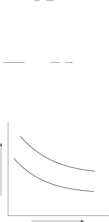
system and the anodes is shown in the Sunde equation:
R=
0.00521P
NL
L
d–1
L
S
N)=+(.log.log.23
82
23 0656
where R = resistance (ohms), P = soil resistivity (ohm-cm), N = number of
anodes, L = anode length (ft), d = diameter of anode (ft), and S = distance
between anodes (ft).
Figure 9.3 shows the typical plotting of the results of this equation. Different
anodic shapes will have different curves.
Number of Anodes
Resistance
FigurE 9.3
Plot of Sunde equation.
Cathodic Protection 303
9.2.1.2 Anode Materials and Backfill
The use of magnesium as a sacricial anode has already been discussed. For
use with impressed current, auxiliary anodes are usually formed of scrap iron
or graphite. Scrap iron is consumed at a considerably faster rate than graphite
(15 to 20 lb/A-yr vs. 2 lb/A-yr); however, graphite costs more — both initially
and in operating expense. Graphite requires more power than scrap iron. It is
also more fragile, and greater care must be taken during installation. Under
certain conditions, the advantage of the 8 to 10 times longer life outweighs the
added costs, particularly in areas where replacement poses problems.
Platinum-clad or 2% silver-lead electrodes that use impressed current have
been used for the protection of structures in seawater. The latter anodes are
estimated to last 10 years, whereas sacricial magnesium anodes require
replacement every 2 years. On occasion, aluminum electrodes have been
used in freshwaters.
Because the effective relativity of soil surrounding an anode is limited to
the immediate area of the electrode, the local distance is generally reduced
by using backll. For impressed current systems, the anode is surrounded
with a thick bed of coke mixed with 3 to 4 parts gypsum to 1 part sodium
chloride. The consumption of the anode is reduced somewhat because the
coke backll is a conductor and carries part of the current. If the anode is
immersed in a riverbed, lake, or ocean, backll is not required.
Auxiliary anodes need not be consumed to fulll their purpose. Conversely,
sacricial anodes are consumed no less to supply an equivalent current than
is required by Faraday’s law.
For magnesium anodes, backll has the advantage of reducing the resis-
tance of insulating corrosion-product lms as well as increasing the con-
ductivity of the immediate area. A typical backll consists of a mixture of
approximately 20% bentonite (for retention of moisture), 75% gypsum, and
5% sodium sulfate.
9.2.2 impressed Current Systems
For these systems, the source of electricity is external. A rectier converts
high voltage to a low-voltage DC current. This direct current is impressed
between buried anodes and the structure is protected.
It is preferable to use inert anodes, which will last for the longest possible
time. Typical materials used for these anodes are graphite, silicon, titanium,
and niobium plated with platinum.
For a given voltage, the current is limited by electrolyte resistivity and by
the anodic and cathodic polarization. With the impressed current system, it
is possible to impose whatever potential is necessary to obtain the current
density required, by means of the rectier.
Electric current ows in the soil from the buried anode to the underground
structure, to be protected. Therefore, the anode must be connected to the
304 Fundamentals of Corrosion
positive pole of the rectier, and the structure to the negative pole. All cables
from the rectier to the anode and to the structure must be electrically insu-
lated. If not, those from the rectier to the anode will act as an anode and
deteriorate rapidly, while those from the rectier to the structure may pick
up some of the current, which would then be lost for protection.
9.2.2.1 Current Requirements
The specic metal and environment will determine the current density
required for complete protection. The applied current density must always
exceed the current density equivalent to the measured corrosion rate under
the same conditions. Therefore, as the corrosion rate increases, the impressed
current density must be increased to provide protection.
Factors that affect current requirements are:
1. The nature of the electrolyte
2. The soil resistivity
3. The degree of aeration
The more acidic the electrolyte, the greater the potential for corrosion and the
greater the current requirement. Soils that exhibit a high resistance require a
lower cathodic current to provide protection. In an area of violent agitation or
high aeration, an increase in current will be required. The required current to
provide cathodic protection can vary from 0.5 to 20 mA/ft
2
of bare surface.
Field testing may be required to determine the necessary current density
to provide cathodic protection in a specic area. These testing techniques
will only provide an approximation. After completion of the installation,
it will be necessary to conduct a potential survey and make the necessary
adjustments to provide the desired degree of protection.
9.2.2.2 Anode Materials and Backfill
Although it is generally preferred to use inert anodes, it is possible to use
scrap iron. Scrap iron is consumed at a considerably faster rate than graphite
or other inert anode material. The advantage of scrap iron is a lower initial
cost and lower operating cost because its power requirements are less. In
areas where replacement poses a problem, the cost of using the more inert
anodes outweighs the reduced cost of the scrap iron.
Platinum-clad or 2% silver-lead electrodes have been used for the protec-
tion of structures in seawater and are estimated to last 10 years, whereas
sacricial magnesium anodes have a life of 2 years.
Because the effective resistivity of the soil surrounding an anode is limited
to the immediate area of the anode, this local resistance is usually reduced
using backll. The anode is usually surrounded by a thick bed of coke mixed

Cathodic Protection 305
with 3 or 4 parts gypsum to 1 part sodium chloride. The consumption of the
anode is reduced somewhat because the coke backll carries some of the
current. Backll is not required when the anode is immersed in a riverbed,
lake, or ocean.
9.2.2.3 Testing for Completeness of Protection
Once the system has been installed, it must be tested for completeness of
protection. The preferred method is to take potential measurements. By
measuring the potential of the protected structure, the degree of protection,
including overprotection, can be determined. The basis for this determina-
tion is the fundamental concept that cathodic protection is complete when
the protected structure is polarized to the open-circuit anodic potential of
the local action cells.
The reference electrode is placed as close as possible to the protected struc-
ture to avoid and to minimize any error caused by internal resistance (IR)
drop through the soil. For buried pipelines, a compromise location is directly
over the buried pipe at the soil surface because cathodic protection currents
ow mostly to the lower surface and are minimum at the upper surface of
the pipe buried a few feet below the surface.
The potential for steel is –0.85 V vs. the copper-saturated copper sulfate
half-cell, or 0.53 V on the standard hydrogen scale. The theoretical open-
circuit anodic potential for other metals may be calculated using the Nernst
equation. Several typical calculated values are shown in the table:
Metal E
o
(V)
Solubility
Product M(OH)
2
OH
2
Scale
(V)
O vs. Cu-CuSO
4
Reference (V)
Iron 0.440 1.8 × 10
−15
−0.59 −0.91
Copper –0.337 1.6 × 10
−19
0.16 −0.16
Zinc 0.763 4.5 × 10
−17
−0.93 −1.25
Lead 0.126 4.2 × 10
−15
−0.27 −0.59
Overpotential of steel structures, to a moderate degree, does not cause any
problems. The primary disadvantages are waste of power and increased con-
sumption of auxiliary anodes. When overprotection is excessive, hydrogen can
be generated at the protected structure in sufcient quantities to cause blistering
of organic coatings, hydrogen embrittlement of the steel, or hydrogen cracking.
Overprotection of systems with amphoteric metals (e.g., tin, lead, alumi-
num, zinc) will damage the metal by causing increased attack instead of
reduced corrosion. This stresses the need for making potential measure-
ments of protected structures.
There are several ways that the effectiveness of protection can be checked.
The rst two methods are qualitative and do not provide data about

306 Fundamentals of Corrosion
whether enough or more than enough current is being supplied. Potential
measurements, the third method, is of prime importance.
1. Coupon test. A metal coupon is shaped to conform to the contour
of the pipe, weighed, and attached by a braze-connected cable to
the pipe. Both the cable and the surface between the coupon and
the pipe are coated with coal tar. The coupon is allowed to remain
buried for weeks or months, uncovered, cleaned, and weighed. The
weight loss, if any, is an indication as to whether or not the cathodic
protection is complete.
2. Colorimetric test. A piece of absorbent paper soaked in potassium fer-
ricyanide solution is placed in contact with a cleaned section of the
buried pipeline and the soil replaced. After a relatively short time,
the paper is retrieved. A blue ferrous/ferricyanide reaction indicates
incomplete cathodic protection, whereas an absence of blue on the
paper indicates that cathodic protection is complete.
3. Potential measurements. By measuring the potential of the protected
structure, the degree of protection, including overprotection, can
be quantitavely determined. This measurement is the generally
accepted criterion and is used by corrosion engineers. The basis for
this determination is the fundamental concept that cathodic protec-
tion is complete when the protected structure is polarized to the
open-circuit anodic potential of the local action cells.
The reference electrode for making this measurement should be placed
as close as possible to the protected structure to avoid and to mini-
mize an error caused by internal resistance (IR) drop through the
soil. Such IR drops through corrosion product lms or insulating
coatings will still be present regardless of precautions taken, tending
to make the measured potential more active than the actual poten-
tial at the metal surface. For buried pipelines a compromise loca-
tion is taken directly over the buried pipe at the soil surface because
cathodic protection currents ow mostly to the lower surface and are
minimum at the upper surface of the pipe buried a few feet below
the soil surface.
9.3 Use with Coatings
Insulating coatings are advantageous to use with either impressed current or
sacricial anodes when supplying cathodic protection. These coatings need

Cathodic Protection 307
not be pore-free because the protective current ows preferentially to the
exposed metal areas that require protection. Such coatings are useful in dis-
tributing the protective current, in reducing total current requirements, and
in extending the life of the anode. For example, in a coated pipeline, the cur-
rent distribution is greatly improved over that of a bare pipeline, the number
of anodes and the total current required are less, and one anode can protect
a much longer section of pipeline. Because the Earth is a good electrical con-
ductor and the resistivity of the soil is localized only within the region of
the pipeline or electrodes, the limiting length of pipe protected per anode is
imposed by the metallic resistance of the pipe and not the resistance of the
soil.
One magnesium anode is capable of protecting approximately 100 ft (30 m)
of bare pipeline, whereas it can provide protection for approximately 5 mi (8
km) of coated pipeline.
In a hot-water tank coated with glass or an organic coating, the life of the
magnesium anode is extended and more uniform protection is supplied to
the tank. Without the coating, the tendency is for excess current to ow to the
side and insufcient current ows to the top and bottom. Because of these
factors, cathodic protection is usually provided with coated surfaces.
9.4 Economics
The cost of cathodic protection is more than recovered by reduced main-
tenance costs, by reduced installation costs, or both. For buried pipelines,
the guarantee that there will be no corrosion on the soil side of the pipe
has made it economically feasible to transport oil and high-pressure natural
gas across the North American continent. It has also permitted the use of
thinner-walled pipe. Wall thicknesses need only be sufcient to withstand
the internal pressures. No extra allowance has to be added for external cor-
rosion. This saving alone has sometimes more than paid for the installation
of the cathodic equipment.
Similarly, other cathodic protection systems have more than paid for their
installation costs, reduced maintenance costs by longer operating periods
between routine inspections and maintenance periods.