Sarkar N. (ed.) Human-Robot Interaction
Подождите немного. Документ загружается.

Modeling and Control of Piezoelectric Actuators for Active Physiological Tremor Compensation
381
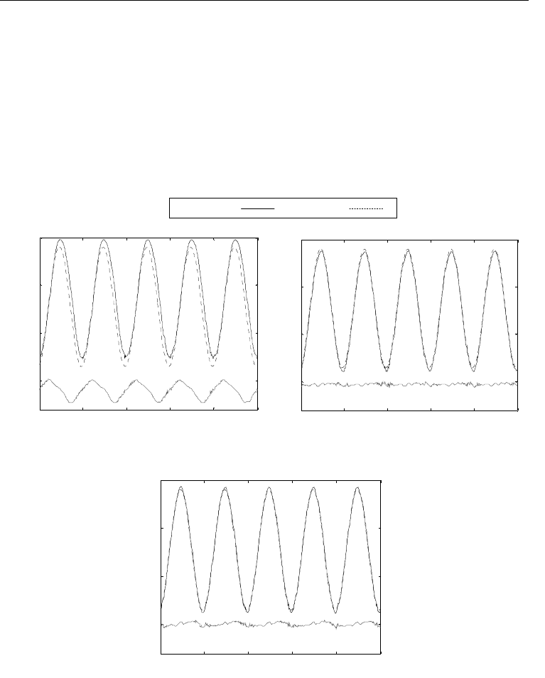
As shown in Fig. 13, at 19 Hz, the tracking rmse of the rate-independent controller is almost
double that of the rate-dependent controller and will continue to worsen as the frequency
increases. Fig. 14 shows the results of the different controllers. Fig. 14(a) plots the hysteretic
response of the piezoelectric actuator with a proportional controller. Fig. 14(b) and Fig. 14(c)
presents the tracking ability of the rate-independent and rate-dependent inverse
feedforward controllers respectively. The rate-independent controller is based on the
modified PI hysteresis model identified at the same 10Hz, 12.5
μm p-p sinusoid.
Both the rate-independent and rate-dependent controllers significantly reduced the tracking
error due to the piezoelectric hysteretic behaviour. However, the tracking accuracy of the
rate-independent controller deteriorates when the frequency deviates from 10 Hz.
Meanwhile, the rate-dependent controller maintained a smaller rmse and maximum error.
Figure 14. Rmse and maximum errors of the rate-independent and rate-dependent
controllers in tracking 12.5
μm p-p stationary sinusoids at different frequencies
Measure Desired
0.1 0.2 0.3 0.4 0.5
0
5
10
15
Displacement (μm)
Time (s)
Error
0.1 0.2 0.3 0.4 0.5
0
5
10
15
Displacement (μm)
Time (s)
Error
0.1 0.2 0.3 0.4 0.5
0
5
10
15
Displacement (μm)
Time (s)
Error
0.1 0.2 0.3 0.4 0.5
0
5
10
15
Displacement (μm)
Time (s)
Error
0.1 0.2 0.3 0.4 0.5
0
5
10
15
Displacement (μm)
Time (s)
Error
0.1 0.2 0.3 0.4 0.5
0
5
10
15
Displacement (μm)
Time (s)
Error
(a) Without Controller
(b) Rate-Independent Controller
(c) Rate-Dependent Controller
Human-Robot Interaction
382
0.5 1 1.5 2 2.5 3
0
5
10
15
Displacement (μm)
Time (s)
(a)
Error
0.5 1 1.5 2 2.5 3
0
5
10
15
Displacement (μm)
Time (s)
(b)
Error
0.5 1 1.5 2 2.5 3
0
5
10
15
Displacement (μm)
Time (s)
(c)
Error
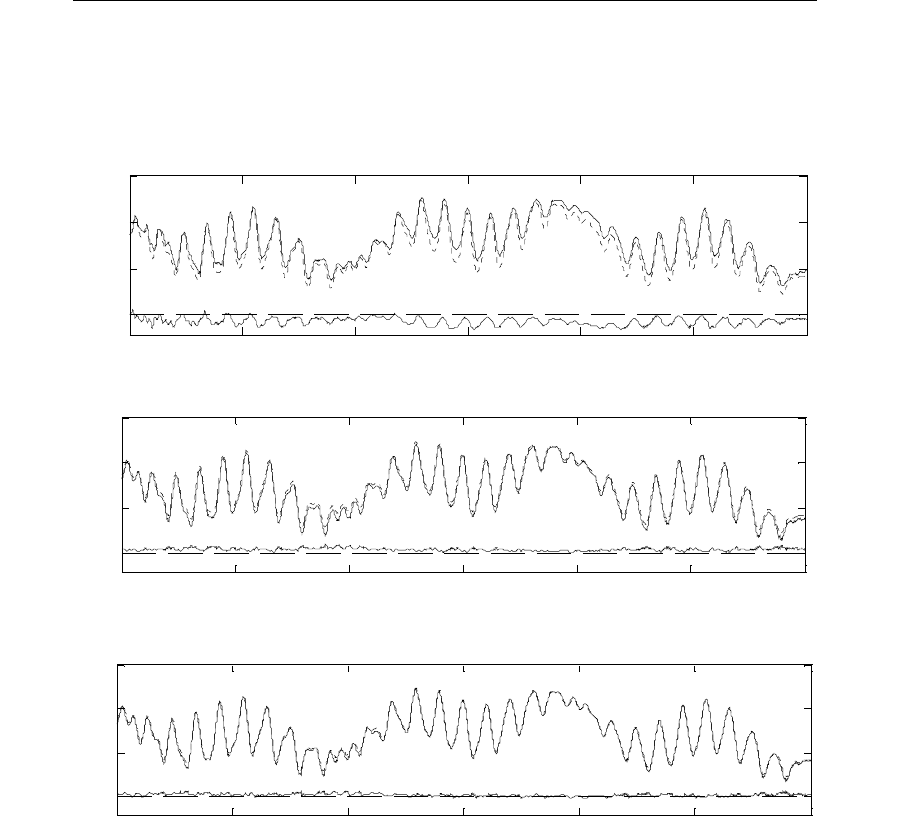
5.3 Multi-Frequency Nonstationary Experiment
The second experiment is an experiment to test the ability of the controllers to track a multi-
frequency nonstationary motion profile. Both the feedforward controllers do improve the
tracking capability. However, the rate-dependent controller did noticeably better. The result
is shown in Fig. 15 and summarised in table 2.
Figure 15. Experimental open-loop tracking results of a multi-frequency, nonstationary
dynamic motion profile. The motion profile is made up of superimposed modulated 1, 10,
and 19 Hz sinusoids with time-varying amplitudes. The rate-independent controller is based
on the modified PI hysteresis model identified at the same 10Hz, 12.5
μm p-p sinusoid.
Transient error is observed for the rate-independent controller in the first 2 seconds.(a)
Without compensation. (b) Rate-independent controller. (c) Rate-dependent controller

Modeling and Control of Piezoelectric Actuators for Active Physiological Tremor Compensation
383
Without model Rate-independent Rate-dependent
rmse ±
σ
(μm)
1.02
± 0.07 0.31 ± 0.03 0.15 ± 0.003
(%)
amplitudep-p
rmse
9.2 2.8 1.4
max error
±
σ
(μm)
1.91
± 0.08 0.89 ± 0.04 0.59 ± 0.06
(%)
amplitudep-p
errormax
17.3 8.0 5.3
The rmse and max errors are the mean results over a set of seven 5-second (5000 data points)
experiments.
Table 2. Measured Performance of the Rate-Independent and Rate-Dependent Inverse
Feedforward Controllers in Tracking Multi-Frequency (1, 10 and 19 Hz) Nonstationary Signals
The rate-dependent controller registers a tacking rmse less than half of that of the rate-
independent controller. Maximum tracking errors for both controllers occur in the transient
phase. This might explain why the improvement in maximum error with the rate-dependent
controller is not as large as the improvement in rmse. One limitation of all PI-type hysteresis
models is that singularity occurs when the first PI weight is 0 as seen in equation (13). Also,
when the slope is negative, the inverse hysteresis loading curve violates the fundamental
assumption that it should be monotonically increasing. Thus, the inverse model will be lost.
In order to maintain a good tracking accuracy for high velocity by having small threshold
intervals, a method to solve the singularity problem is proposed in the next section.
6. Using a different Domain to solve Singularity Problem
The PI operator, while being able to model the hysteresis behaviour of a piezoelectric actuator
well, has one major inadequacy: the inverse of the operator does not exist when the slope of
the hysteretic curve is not positive definite, i.e. singularity occurs when the PI weights 0.
Such ill conditioned situations arise when the piezoelectric actuators are used to actuate heavy
loads or when operating at high frequency. Another possible situation for ill condition is when
small intervals between the threshold values are used. Presently, most people avoid this
problem by having larger intervals between the threshold values. However, this is not solving
the problem and resulted in higher error around the turning point.
This section presents how the authors managed to overcome this problem by mapping the
hysteresis through a linear transformation onto another domain, where the inversion would
be better behaved. The inverse weights are evaluated in this domain and are subsequently
used to compute the inverse hysteresis model, which is to be used in the feedforward
controller, before the inverse model is transformed back to the original domain. The
singularity problem is first illustrated, followed by the solution to map the ill-conditioned
hysteresis onto a singularity-free domain.
6.1 Illustration of Problem
As seen in Fig. 5, using the inverse as a feedforward controller linearizes the response.
Unfortunately, to use the hysteresis model, the operating frequency must not be too high as
the hysteresis non-linearity will become more severe and like most models, the classical
Human-Robot Interaction
384
Prandtl-Ishlinskii model is also unable to function as a feedforward controller when the
largest displacement does not occur at the highest input signal (Fig. 6). The inverse model
equation (13) fails when the convex curve is encountered.
Most systems can be approximated as a spring mass damper system. When driven at high
velocity, the actuator/mechanism has a high momentum at the turning point, especially if a
rapid change is made. The large momentum tends to keep the system in motion and the large
momentum results in the convex curve. Similar explanation is applicable for large loads.
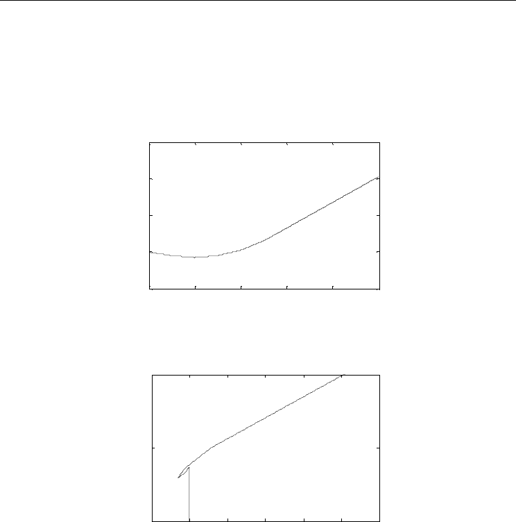
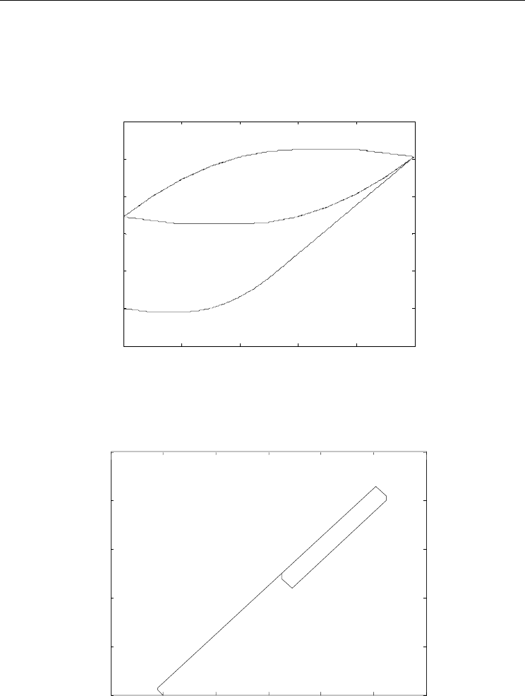
Figure 16. Loading Curve of Hysteresis example involving negative gradient
Figure 17. Inverse Loading Curve of example to illustrate failure of PI inverse operator
when negative gradient is encountered
There is also an inevitable trade-off between modeling accuracy and inversion stability. The
modeling of the hysteretic loop gets better with the number of backlash operators used in
the modeling. However, as the piecewise continuous interval represented by each backlash
operator shrinks, there is a greater chance for the reciprocal of the PI weights to be ill
conditioned, especially at the hysteretic curve turning points. An example to show that the
inverse model equation (13) fails when the convex curve is encountered is illustrated here.
Given weights of
T
h
w
&
= [-0.2 0.1 0.2 0.2 0.2 0.2] and
r
&
= [ 0 1 2 3 4 5] for an application where
the amplitude of the periodic input voltage is 10V. The loading curve is shown in Fig. 16.
0 2 4 6 8 10
-2
0
2
4
6
Input Voltage
Displacement
-1 0 1 2 3 4 5
0
5
10
Input Voltage
Displacement
Modeling and Control of Piezoelectric Actuators for Active Physiological Tremor Compensation
385
Applying equation (13) to the get the inverse PI parameters, we obtain
T
h
w'
&
= [-5 -5 20 -
6.6667 -1.333 -0.5714] and
'
r
&
= [0 -0.2 -0.3 0.1 0.6]. Fig. 17 illustrates the inverse curve that
will be obtained using equation (13). The two graphs are not a reflection of each other along
the 45 degrees line. This simple proof clearly illustrates that equation (13) has failed as an
inverse function when the condition of positive gradient is not met. Zero gradient is not
demonstrated in this example as it is clear that the reciprocal of 0 is a singular point.
6.2 Obtaining Inverse Model in a Different Domain
6.2.1 Intuition of Proposed Method
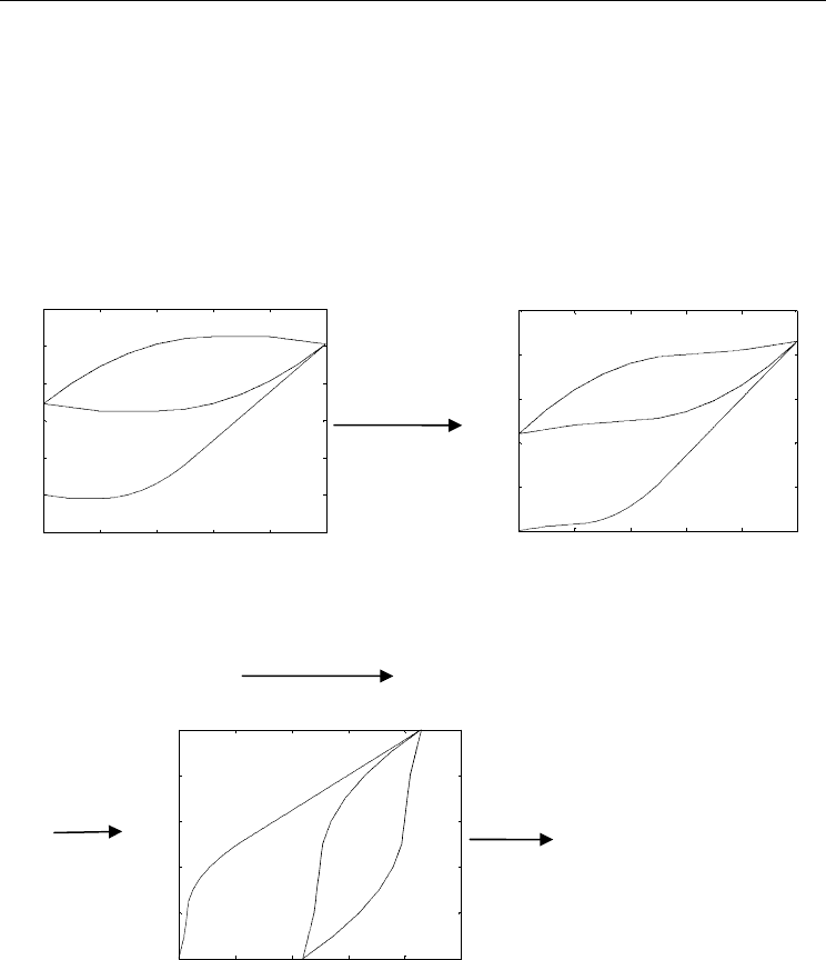
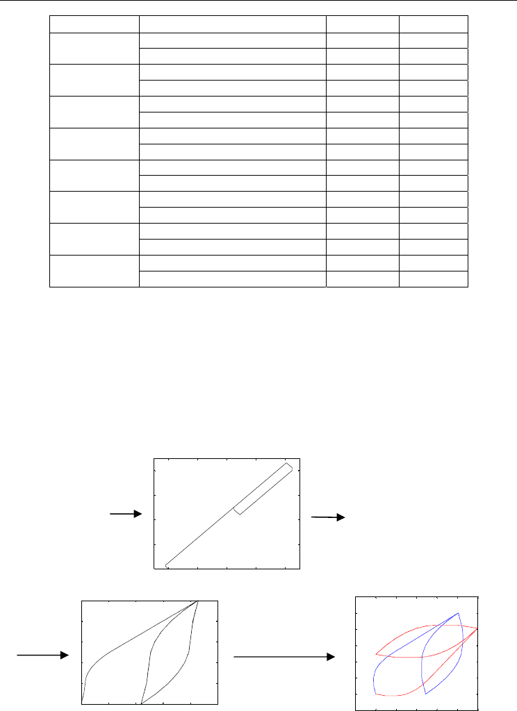
Figure 18. Transformation
Figure 19. Method to Obtain Appropriate Input Voltage
With the singularity problem, the author came up with the idea to model the hysteresis in
an alternative domain when the inverse of the PI model fails in a situation like the largest
displacement not occurring at the highest input signal (Fig. 6). A transformation is used to
map y (the original hysteretic displacement values) to z, which has no singular points as
shown in Fig. 18. The inverse model can now be obtained in the new domain. The
desired y
correspondin
g
z values
z = f(y)
0 2 4 6 8 10
0
2
4
6
8
10
voltage
z
appropriate
input voltage
0 2 4 6 8 10
-2
0
2
4
6
8
10
0 2 4 6 8 10
0
2
4
6
8
10
z = f(y)
y
Input volta
g
e
Input
voltage
z

Human-Robot Interaction
386
appropriate input voltages can now be obtained using the inverse model found in the new
domain as shown in Fig. 19.
The saturation operator is just another transformation and thus can be ignored for the time
being. The inverse of the saturation operator can be applied after the inverse of the
singularity-free model.
The desired value displacement y is first passed through the transformation function to
obtain the corresponding new domain z value. This z value is then passed through the
inverse model obtained in the new domain to get the appropriate input voltages.
6.2.2 Obtaining the Inverse Model in a different Domain
Although the inverse of the PI model fails, PI model can still describe the pneumonia path
like figure 4. The PI parameters for the ill-conditioned hysteresis can be obtained as shown
in section 2. Recall that equation (2) can describe the hysteresis.
[]
)(,)(
0
tyxHwty
r
T
h
&
&
&
= (3)
Using least square method,
T
h
w
&
is be obtained. To illustrate the transformation, nine points
(x
0
to x
8
) are labelled in Fig. 20. Negative gradient for the loading curve occurs between x
0
and x
1
while 0 gradient is between x
1
and x
2
. In the hysteresis loop, region between x
3
to x
4
and x
6
to x
7
has negative gradient while x
4
to x
5
and x
7
to x
8
contain gradient value 0.
The labelled points x
0
to x
8
can be calculated using:
¦
>==
==
¦
=
=
=
+
=
max
1
max21
121
1
0
0 whereotherwise,
;exists,0If
;0
j
j
h
ii
i
j
j
h
wrxx
rxrxw
x
;2
;2
;0
;2
;2
;2
268
167
6
235
134
max3
xxx
xxx
x
xxx
xxx
rx
+=
+=
=
−=
−=
=
(22)
To obtain the points a
0
to a
8
, x
0
to x
8
are substituted into equation (4).
The transformation function f(x) as shown in Fig. 19 is a function that changes the weights of
the PI hysteresis model. The weights of the transformed hysteresis are obtained via:
°
°
°
°
¯
°
°
°
°
®
¦
>
¦¦
−
¦
=
¦
−
¦
<
¦¦
−−
=
==
−
=
=
−
=
==
−
=
i
j
j
h
i
j
i
j
j
h
j
h
i
j
j
h
i
j
j
h
i
j
j
h
i
j
i
j
j
h
j
h
i
h
www
wwc
www
w
11
1
1
2
1
1
1
2
11
1
1
2
2
0,
0,
0,
(23)
Modeling and Control of Piezoelectric Actuators for Active Physiological Tremor Compensation
387
where c is a positive non-zero constant to force the transformed gradient to be positive non-
zero number. Fig. 21 shows the relationship of z and y after passing through the
transformation function. The constants a
i
and b
i
are the corresponding y and z values
respectively to input voltage x
i
.
0 2 4 6 8 10
-2
0
2
4
6
8
10
Input Voltage
Displacement
(x
0
,a
0
)
(x
1
,a
1
) (x
2
,a
2
)
(x
3
,a
3
)
(x
4
,a
4
)(x
5
,a
5
)
(x
6
,a
6
)
(x
7
,a
7
)
(x
8
,a
8
)
Figure 20: Graph of an ill-conditioned Hysteresis with points x
0
to x
8
labelled
Figure 21: Relationship of z (new domain) with y (real displacement)
-2 0 2 4 6 8 10
0
2
4
6
8
10
y
z
(a
0
,b
0
)
(a
1
,b
1
)
(a
2
,b
2
)
(a
3
,b
3
)
(a
4
,b
4
)
(a
5
,b
5
)
(a
6
,b
6
)
(a
7
,b
7
)
(a
8
,b
8
)

Human-Robot Interaction
388
Because of the way the transformation function is formed, all the gradients of the line are 1, -
1 or infinite. Points b
0
to b
8
are obtain using (24).
];[2
];[
];[
];[2
];[
];[
];[
;
;0
1278
6767
5656
1245
3434
2323
1212
11
0
xxcbb
aabb
aabb
xxcbb
aabb
aabb
xxcab
ab
b
−×+=
−−=
−+=
−×−=
−−=
−+=
−×+=
−=
=
(24)
With these points, the relationship between z to y is in table 3.
7. Simulation and Experimental Results of Transformation Method
7.1 Simulation
This section demonstrates how the transformation function is used to help the reader in
applying the equations shown to their applications.
The actual ill conditioned hysteresis of the system is first obtained and modelled using
Prandtl-Ishlinskii operator. The hysteresis curve is then mapped onto another domain using
the transformation function illustrated in section 6. A well-conditioned hysteresis is
obtained as seen in Fig.18. The inverse parameters of the well-conditioned hysteresis curve
in the new domain are obtained using (13) and the inverse model is obtained.
After obtaining the inverse function in the new domain, the desired y values are passed
through the transformation to obtain the desired z values using table 4, starting with A=0,
B=0 and C=0. The desired z values are then passed through the inverse Prandtl-Ishlinskii
model to obtain the required input x. An example is illustrated in Fig. 22, where the red
graph is the hysteresis and blue graph is the inverse curve.
y value Corresponding z value Equation
a
0
to a
1
y
z
−=
(25)
a
1
to a
2
,
2
bz = , any value between b
1
to b
2
(26)
a
2
to a
3
,
22
abyz −+=
(27)
a
3
to a
4
33
abyz ++−=
(28)
a
4
to a
5
5
bz = , any value between b
4
to b
5
(29)
a
5
to a
6
55
abyz −+=
(30)
a
6
to a
7
66
abyz ++−=
(31)
a
7
to a
8
8
bz = , any value between b
7
to b
8
(32)
Table 3. Relation between the two domains
Modeling and Control of Piezoelectric Actuators for Active Physiological Tremor Compensation
389
Condition (1) Condition (2) Equation Setting
|y(t)| < |a
1
| && y(t) < y(t-1) (25)
A’B’C’
otherwise
(26)
y(t) = a
2
(26)
A’B’C
otherwise
(27) B=1
y(t) a
3
(27)
A’BC
otherwise
(28) A=1
y(t) a
4
(28)
ABC
otherwise
(29) B=0
y(t) = a
5
(29)
AB’C
otherwise
(30)
y(t) a
6
(30)
AB’C’
otherwise
(31) B=1
y(t) a
7
(31)
ABC’
otherwise
(32) A=0
y(t) = a
8
(32)
A’BC’
otherwise
(27)
Table 4. Equations to obtain y values
The value of C is as follows:
¯
®
−>
−<
=
)()(,1
)()(,0
Ttyty
Ttyty
C
(33)
As shown in Fig. 22, the final inverse graph (blue) is a reflection of the hysteresis graph (red)
along the line y = x. This clearly illustrates the ability of the transformation function to
obtain the inverse of the hysteresis curve. The transformation function has no effect on well-
conditioned hysteresis graphs as x
2
= x
1
= x
0
.
Figure 22. Simulation to illustrate that the inverse can be obtained with desired y as input
0 2 4 6 8
0
2
4
6
8
0 2 4 6 8 10
0
2
4
6
8
10
appropriate
input
voltage
-2 0 2 4 6 8 10
-2
0
2
4
6
8
10
12
corresponding z
displacement y
Human-Robot Interaction
390
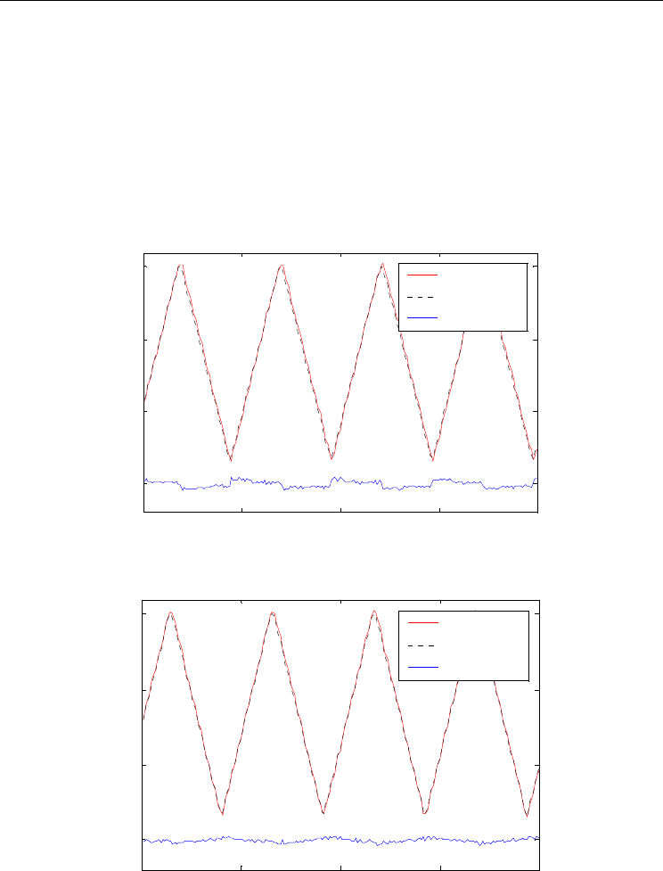
7.2 Experimental Results
The experiment setup is as described in section 5.1. Three types of experiments were carried
out. The first set of experiments is 8 Hz triangular wave. Triangular wave is used because of
its constant velocity. This is followed by varying amplitude linear motion with varying
velocity to demonstrate the capability to model rate-dependent. The last experiment is a
varying frequency with varying amplitude sinusoidal wave.
The same model is being used for both with and without mapping. The first experiment’s
desired displacement is a triangular wave with the velocity high enough for the first weight
to go into the negative region.
0 50 100 150 200
0
5
10
15
Time
(
ms
)
Displacement (μm)
Measured
Desired
Error
Figure 23. Triangular Wave Without Mapping
Figure 24. Triangular Wave With Mapping
0 50 100 150 200
0
5
10
15
Time (ms )
Displacement (μm)
Measured
Desired
Error