Rusko A., Thompson M. Power Quality in Electrical Systems
Подождите немного. Документ загружается.

the battery time is usually only several minutes. The transfer from util-
ity line to E/G set, including starting and stabilizing the generator for
frequency and voltage, can be accomplished in about 10 s. Sometimes a
short time delay is introduced in starting to avoid too frequent E/G
starts for short-time voltage sags and interruptions that can be handled
by the batteries of the UPS.
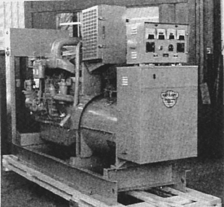
Engine-generator sets are available from 50 to 2500 kVA. A 218-kVA
diesel-engine generator set is shown in Figure 13.7 [13.1]. For larger
loads, it is common to employ multiple E/G sets operating in parallel to
obtain reliability through redundancy and to have a set available for
maintenance. In addition, electric power is required for non-UPS load—
that is, air conditioning, lighting, and water pumps. Combustion tur-
bines are also employed to drive generators in standby applications.
Standards
The major problem for the installation of E/G sets is environmental. The
sets produce noise, exhaust, and vibration; they require coolant air or
water, fuel, and fuel systems; they are heavy and require adequate foun-
dations. A list of codes and standards governing E/G sets as an alter-
native to utility power includes the following:
■ ANSI/IEEE 446-1995, “Recommended Practice for Emergency
and Standby Power Systems for Industrial and Commercial
Applications” [13.2]
Standby Power Systems 195
Figure 13.7 Diesel engine-generator set. Rating: 175 kW, 0.8 PF,
480 Y / 277 V, 60Hz [13.1].
■ NFPA 110-2002, “Standards for Emergency and Standby Power
Systems” [13.3]
■ NFPA 70-2005, “ National Electrical Code” specifically [13.4]
■ Art. 700, “Emergency Systems”
■ Art. 701, “Legally Required Standby Power Systems”
■ Art. 702, “Optional Standby Power Systems”
Component parts of an E/G set installation
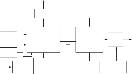
The component parts or subsystems of an E/G set are shown in
Figure 13.8. Detailed information is given in On-Site Power Generation:
A Reference Book, fourth edition [13.5]. The parts are described as follows:
■ Engine: Gasoline, diesel, internal combustion engine, or a combus-
tion gas turbine. Turbine requires minutes to start and acquire load,
compared to seconds for an internal combustion engine.
■ Generator: Three-phase salient-pole (1800 r/min or 3600 r/min)
exciter for field current and damper windings for parallel operation.
■ Fuel: Gasoline, diesel oil, natural gas, or another. Requires day tank
and offsite tank, pumps, piping, vents, and filters.
■ Coolant: Radiator and fan mounted on the engine, or external to the
engine, with ducts to the engine.
■ Exhaust: Muffler and exhaust piping to discharge gases and control
noise.
■ Starter: Electric motor, battery, and charger, or pneumatic means and
high-pressure air storage. Start initiated by signal from manual switch
or transfer switch.
196 Chapter Thirteen
Start
signal
Coolant
Fuel
Exhaust
To
load
Generator
Exciter
Engine
Voltage
regulator
Circuit
breaker
Battery
start
Control
speed
frequency
Protective
relays
Figure 13.8 Block diagrams. Functions of E/G set.
■ Control: Electronic isochronous governor for independent operation
and when synchronized to other generators and/or to the utility line.
Active power load division.
■ Generator Protection: Relays to monitor load current, terminal
voltage, reverse power, frequency, over temperature, to operate alarms
and trip the circuit breaker.
■ Voltage Regulator: Electronic regulator for the exciter or main field
current to regulate terminal voltage. Reactive power load division.
■ Synchronizer: Controls engine speed and circuit breaker closing
when the E/G set is to operate in synchronism with the utility line
and/or other E/G sets.
■ Circuit Breaker: Electrically operated. Rated for generator over-
load current and for maximum three-phase short-circuit current.
Operation. The E/G set is a universal, useful, piece of equipment at a
site whose output supplements utility service. Its operation includes the
following functions:
■ Loads: Include UPS, lighting, air conditioning, heating, fans, pumps,
electronic equipment, and appliances. To a degree, loads can draw
non-sinusoidal current (harmonics) and be unbalanced. The generator
must have low subtransient reactance (damper windings) and/or be
oversized for harmonic load current.
■ Emergency Operation: The controls of the transfer switch order the
E/G set to start when an interruption in utility voltage is detected (or
a manual test signal is entered). When the generator voltage has sta-
bilized at the correct amplitude and frequency, the transfer switch
transfers the load to the E/G set. Starting and transfer usually takes
about 10 s. When utility power is restored, the controls allow the E/G
set to run for about 30 min before the transfer switch transfers the
load back to the utility power. Multiple engine-generator sets start in
sequence.
■ Testing: E/G sets for emergency service should be tested about once
a week, and allowed to run at least 30 min. The generator can be
loaded with one of the following: (1) a dummy load, (2) a facility load,
or (3) it can be synchronized to the utility line. The test can be initi-
ated manually or automatically from a programmable controller.
■ Non-emergency Standby: The E/G can be used to provide power to
equipment or facilities when the normal power source is not avail-
able—for example, when they are under construction or maintenance
work is being done. The UPS can be placed on by-pass. Adequate fuel
must be available.
Standby Power Systems 197
■ Parallel Operation: Two or more E/G sets can be operated in par-
allel for redundancy, to secure more than one set’s power, and to
handle large motor starting. The governors and voltage regulators
must insure parallel operation at the required voltage and frequency,
as well as active and reactive power division.
Transfer switches
The purpose for a transfer switch is shown in Figure 13-5. The switch
connects the load, in this case a UPS, to either the utility source or
to an E/G set. The operation is usually conducted when power from
the utility line is interrupted and the output of the E/G set must
supplement the capacity of the batteries of the UPS. The transfer
switch has other functions, such as transferring between two feed-
ers or transformers, and transferring power to a motor from a failed
feeder to an alternate feeder. The subject is covered extensively in ref-
erence [13.5].
Standards. Pertinent standards on transfer switches include the
following:
■ NEMA, “AC Automatic Transfer Switches,” ICS 2-44 [13.6]
■ NFPA, “National Electrical Code,” NFPA 70-2005 [13.4]
■ UL, Standard for Automatic Transfer Switches, fourth edition, UL
1008 [13.7]
■ NFPA, “Emergency and Standby Power Systems,” NFPA 110-2005
[13.3]
Types of transfer switches. Several types of transfer switches are avail-
able and include the following:
■ Manual: The transfer switch can consist of a double-throw multi-
pole switch, or two mechanically interlocked circuit breakers or
contactors.
■ Automatic Electromechanical
■ Three-pole or four-pole to switch three phases with or without
neutral.
■ Open or closed transition, which usually requires utility permission
when switching E/G sets with respect to a utility line.
■ Controls, including voltage sensing, engine starting and shutdowns.
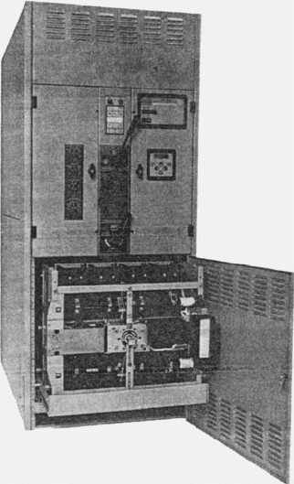
■ By-pass: Incorporates a by pass switch section that can connect the
preferred line to the load while the transfer switch is removed for
maintenance, as shown in Figure 13.9 [13.5].
198 Chapter Thirteen
■ Solid State: Utilizes thyristor or GTO AC switches in each leg, as
shown in Figure 13-6. Transfer switches have been built for switch-
ing utility feeders rated up to 34 kV.
Applications. Applications for transfer switches include nearly every
area of electrical application, particularly those devoted to high relia-
bility and safety. These include the following:
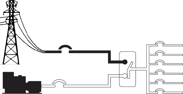
■ Utility to E/G Set: A generic diagram is shown in Figure 13.10. The
shape of the movable contact is typical to obtain a short travel distance
and no ambiguity of contact positions.
■ UPS Supply: Transfer from a utility line to an E/G set to supplement
the UPS battery. Data centers employ up to 10,000 kVA of E/G sets
and suitable transfer switches.
■ Electric-Motor Transfers: For large induction motor–driven fans
and pumps, as in power plants, transfer switches are employed where
two alternate transformers or feeders are provided.
■ Lighting: Alternate and emergency lighting systems supplied by
transfer switches from batteries, inverters, and alternate feeders.
Standby Power Systems 199
Figure 13.9 Automatic transfer
switch with optional bypass- iso-
lation switch [13.5].
Summary
Standby power equipment provides the means to improve the reliabil-
ity of the utility electric power supply to critical load equipment.
Alternate feeders and E/G sets utilizing transfer switches are the prin-
cipal means of providing both power and standby power to UPSs, health
care facilities, and telecommunications systems. The design requires
consideration of all aspects of the existing utility supply and the desired
objectives of the high-reliability system.
References
[13.1] A. Kusko, Emergency/Standby Power Systems, McGraw-Hill, New York, 1989.
[13.2] ANSI/IEEE 446-1995, “Recommended Practice for Emergency and Standby Power
Systems for Industrial and Commercial Applications”.
[13.3] NFPA 110-2005, “Standard for Emergency and Standby Power Systems”.
[13.4] NFPA 10-2005, “National Electric Code”.
[13.5] EGSA, On-Site Power Generation Reference Book, 4th edition, 2002.
[13.6] NEMA ICS 2-447, “AC Automatic Transfer Switches”.
[13.7] UL1008, Standard for Automatic Transfer Switches, 4th edition.
200 Chapter Thirteen
Figure 13.10 Normal/emergency sources. Automatic transfer switch [13.5].
Normal
Automatic
transfer
switch
Loads: Lights
Motors, Heaters, etc.
source
source
Emergency

Chapter
14
Power Quality Measurements
In this chapter, we shall discuss practical issues related to
making power-quality measurements. Any measurement job
requires the proper tools to do that job. The monitoring of
power quality at the supply end, at distribution and
transmission, and at the load end has become of major interest
in recent years. In the following, we will discuss various types
of equipment used in power-quality measurements, and the
proper use and limitations of such equipment.
Multimeters
Multimeters are used to measure voltages, currents, and resistances.
Typical applications of multimeter measurements are line-voltage meas-
urements and imbalance measurements. In making voltage and current
measurements, generally we’re interested in measuring the rms value
of the waveforms. Some subtleties are associated with this measurement.
In one type of multimeter, the input waveform is rectified and aver-
aged, as shown in Figure 14.1a. This method works well for pure sine
waves (where the rms value is the peak value divided by the square root
of two), but for waveforms with harmonics, this method is prone to errors.
Error is especially high for waveforms with a high crest factor.
Several types of multimeters produce “true-rms” readings—that is,
they accurately report the rms value of waveforms with harmonic
distortion. One type of true-rms multimeter employs an rms-to-DC
converter (Figure 14.1b). Several IC manufacturers produce rms-to-
DC converter integrated circuits.
1
Another method of producing true-rms
readings involves a thermal measurement method (Figure 14.1c) [14.1].
201
1
See, for example, Analog Devices and Linear Technology.
Copyright © 2007 by The McGraw-Hill Companies, Inc. Click here for terms of use.
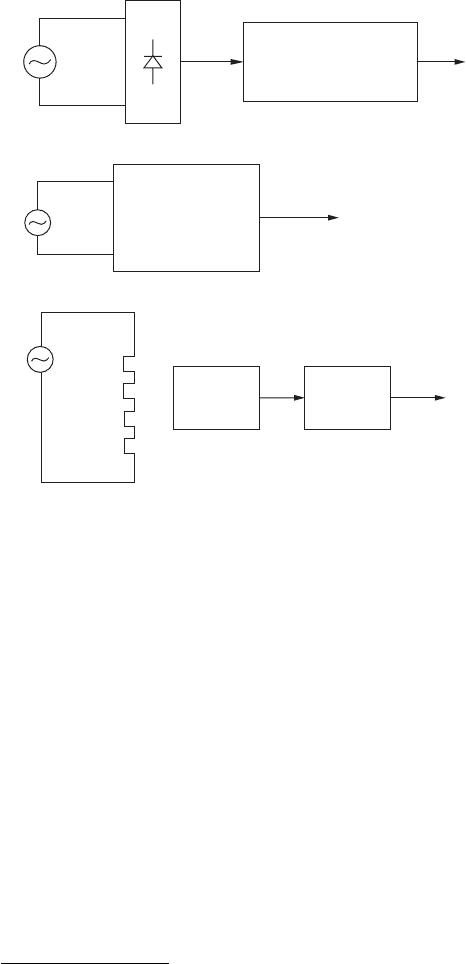
True-rms multimeters are more accurate in the measurement of the
rms value of periodic waveforms.
Oscilloscopes
Today’s oscilloscopes have more than enough bandwidth to display the
harmonics present in all power-quality events. For instance, the 20th har-
monic of the line frequency in the U.S. is 1200 Hz, which is much lower
than the bandwidth of even an inexpensive oscilloscope. Impulsive tran-
sients (like that caused by lightning strikes or power switching) typically
last a few microseconds. It is well within the capability of oscilloscopes
to measure and display these waveforms with good accuracy.
Scopes are often used in conjunction with current probes
2
to measure
AC line currents. Often, differential voltage probe
3
modules are used to
202 Chapter Fourteen
(a)
V
rms
V
s
Average
V
rms
V
s
AC-rms
converter
(b)
Heater
Temp
sensor
Temp. to
DC
converter
V
rms
V
s
(c)
Figure 14.1 Multimeter types for making AC voltage measure-
ments. (a) Rectify and average. (b) Analog computation. (c) Thermal.
2
See, for example, the Tektronix P6042 current probe, which has a response from DC
to 50MHz.
3
The differential probe overcomes the practical problem of using a single-ended scope
probe, which has a signal input and a ground clip.
measure the voltage difference between two points in a system. Many
manufacturers make high voltage differential probes that are compat-
ible with oscilloscope inputs. Typical specifications for differential
probes
4
are
■
Bandwidth: 100 MHz
■
Differential voltage: 5000 V
■
Common-mode voltage: 2000 V
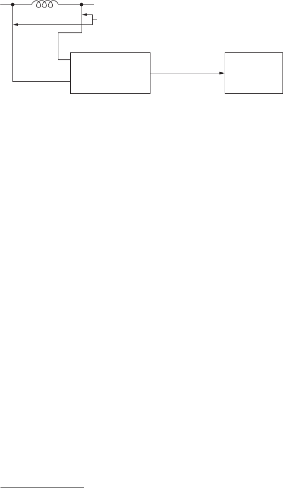
A typical system for making high voltage differential measurements
is shown in Figure 14.2. We see that the output of the differential probe
is a 50- BNC cable
5
that interfaces with an oscilloscope. The differen-
tial probe has a conversion ratio (millivolts per volt) that brings down
the signal levels to the oscilloscope to a manageable level.
Current Probes
Current probes come in several different types. Hall-effect current
probes (like that used in the Tektronix P6042) detect all the way down
to DC by utilizing the “Hall effect.” Hall devices are semiconductors
that generate an output voltage in response to a magnetic field created
by a current. Hall probes have the advantage that they provide output
at DC. Unfortunately, they are prone to drift and should be calibrated
prior to use.
Other types of current probes use current transformers (CTs). CT cur-
rent probes do not give an output at DC since they are based on trans-
former action. A typical test setup using a CT and an oscilloscope is shown
in Figure 14.3. CT current probes give a conversion ratio (volts per amp)
when terminated in the proper resistance—in most cases 50 .
Power Quality Measurements 203
Probe
leads
Differential
probe
Oscilloscope
BNC cable
output
Figure 14.2 Measurement system for making high voltage differential
measurements.
4
See, for example, the Tektronix P5200 high-voltage differential probe.
5
BNC cables are coaxial cables used in instrumentation and video. A BNC cable is char-
acterised by its transmission line characteristic impedance, which is typically 50 or 75
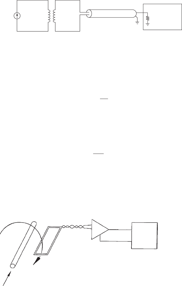
Search Coils
The magnetic field produced by a current can be detected by a “search
coil” as shown in Figure 14.4. The voltage output of the search coil is
found using
where N is the number of turns in the search coil, A is the area of the
coil, and dB/dt is the time rate of change of the magnetic flux density per-
pendicular to the plane of the search coil. In the setup of Figure 14.4,
the magnetic field H and the magnetic flux density B are found using
where r is the mean radius from the current-carrying wire to the search
coil, and m
o
is the magnetic permeability of free space. Note that this
measurement can be affected by stray time-varying fields from sources
other than the current-carrying wire being measured.
B 5 m
o
H
H 5
i
2pr
v
o
5 NA
dB
dt
204 Chapter Fourteen
Circuit
under
test
BNC cable
Oscilloscope
50 Ω
N
P
: N
s
Figure 14.3 A measurement system for making high current measurements using a CT
and an oscilloscope.
H
Amplifier
Analyzer
i
Figure 14.4 A search coil setup [14.2].
[© 1992, IEEE, reprinted with permission]