Rusko A., Thompson M. Power Quality in Electrical Systems
Подождите немного. Документ загружается.

■ Modular design for fast service and reduced maintenance
requirements
■ Rating, for 225 kVA UPS, (Figure 9.7) [9.7]
■ Flywheel power system support for UPS
■ Run time, 13 seconds at UPS full load, 28 seconds at UPS 50 per-
cent load
■ Recharge time, 20 seconds
■ N1 configurable
Uninterruptible Power Supplies 135
AB
Allen-Bradley
AB
Industrial UPS
The double-conversion online Allen-Bradley 1609-P UPS is available in the
3 kVA to 10 kVA power range. Each model is available in various input and
output voltage combination and offers assorted output voltage and receptacle
or hard wired configurations. Its network management card allows users to
monitor and control capabilities via a standard Web browser or RSView.
Rockwell Automation
Figure 9.4 Double-conversion UPS, 3 to 10 kVA [9.5].
SL120 KG + (1) SLB120K160G2
• For data centers, facilities and high
availabiltiy applications
• Output power capacity 120,000VA/
120,000 watts
• Interface port DB-25 Rs-232, contact
closure, parallel card, relay board, triple
chassis for 3 SmartSlots
• Runtime at full/half load 8 min/22 min
• Standard warranty 1 year parts, labor, and
travel with purchase of start-up. Optional
on-site warranties available
Three-phase, on-line
power protection
Silcon
®
120 kVA
Figure 9.5 Double-conversion UPS, 8 min run time, 120 kVA [9.6].
[Courtesy APC]
Figure 9.7 Flywheel UPS, 130 kVA, 25 s [9.7].
[Courtesy Pentadyne Power Corporation]
Sy1000K1000G + SYMBP1000C1G12 +
(3)SYB400K1000GXR-2C
• 1000 kVA/kW 480 V UPS
• Scalable power capacity reduces UPS
oversizing costs
• Configurable for N + 1 internal redundancy
provides high availabilty
• Modular design for fast service and reduced
maintenance requirements
• LCD display provides schematic overview of
critical data
• Fully rated power kVA equals kW. This reduces
cost by eliminating the need for an oversized
UPS for Power Factor Corrected (PFC) loads
Symmetra
∗
MW 1000 kVA
The world’s largest
modular UPS
Figure 9.6 Double-conversion UPS, 1000 kVA [9.6].
[Courtesy APC]
136 Chapter Nine
Flywheel power system
The VSS+ voltage support
solution (VSS) flywheel power
system provides ride-through
protection for a safe system
shutdown of most process
operations or until a standby
engine-generator can come
online. It also handles short-
duration power disturbances so
UPS batteries can be saved for
longer events. A single VSS+
unit provides up to 25 sec. in a
130 kVA UPS and 40 sec. in a
80 kVA UPS. For large systems,
multiple VSS+ system can be
paralleled together without any
additional communication links.
Pentadyne
Uninterruptible Power Supplies 137
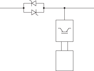
Fuel Cell System (FCS)
- Stand alone system utilizing a PEMFC
- Proprietary technology with proven life
and reliability
- Integrated controller
Power Conditioning System (PCS)
- Converts unregulated DC power from
the fuel-cell to 48 V DC regulated
- Standard industry hardware
Energy Storage System (ESS)
- 3 banks of ultra-capacitors, which provide
a seamless power transition during fuel-cell
start-up
- Standard industry hardware
Figure 9.8 Fuel-cell UPS, 48 V DC power, 4.5 kW [9.8].
[Courtesy UTC Power]
■ Rating, 4.5 kW, (Figure 9.8) [9.8]
■ Fuel cell–powered UPS
■ Ultra capacitors for fuel cell startup
■ Output, 28 V DC
Energy storage
The requirement for stored energy in an uninterruptible (standby) power
system is predicated on at least two parameters: (1) the time duration of
power delivery (term), and (2) the power level (energy). The requirements
further defined by the time duration can be categorized as follows [9.8]:
■
Short Term: Standby systems without available transfer means to
engine-generator sets or alternate utility feeders. These stand-alone
systems range from 100 W to 1000 kW and include 5 to 30 minutes of
stored energy capability, based on estimates of utility outage time.
■
Medium Term: Standby systems with available transfer means to
engine-generator sets, alternate utility feeders, or other sources. These
systems range up to 10,000 kW and include up to 5 minutes of stored
energy capability, based on the time to start engine-generator sets and
make the transfer.
■
Long Term: Standby systems that operate as part of a utility system,
which provide, in addition to standby function, other functions such
as peak shaving, voltage and frequency stabilization, and reactive
power supply. These systems can be rated up to 20 MW and can de-
liver energy for up to 8 hours.
Requirements for uninterruptible power for specific loads can be met
by short- and medium-term systems described earlier.
Batteries
Batteries consist of one or more cells electrically interconnected to
achieve the required voltage, stored energy, and other characteristics.
Two types of operation are important: float and cycling. Float operation
describes batteries in telephone central offices where the batteries main-
tain a relatively constant voltage—for example, 48 V DC. Cycling oper-
ation describes batteries in standby systems—for example, UPS, where
the battery charge is drawn down to supply the inverter and the AC load
when the utility power fails. These batteries for UPS rated 100 kVA and
higher, are typically rated 460 V DC. The batteries are recharged when
utility power returns, or engine generators are started and run [9.8].
The specific energy and energy density of the batteries used for
standby service are shown in Figure 9.9 [9.9]. The application of these
batteries depends on additional factors besides those in the figure.
The batteries employed for standby service are described in the
following [9.8]:
■
Flooded, lead acid batteries: These have been used for UPSs since
the 1960s [9.4], and as the backup for communications power supplies
before 1983 [9.10]. This type of battery requires periodic additions of
water to comply with its specific gravity measurements. It discharges
inflammable gas, and thus requires special facilities for safety. To fa-
cilitate venting, the gas space in flooded cells is open to outside air but
138 Chapter Nine
Li-ion
NiMH
VRLA
NiCd
140
Wh/kg
120
100
80
60
40
20
0
0 50 100
Wh/I
Lighter
Smaller
150 200 250
Flooded
LMP
Figure 9.9 Specific energy and energy density comparison of
batteries: Wh/kg and Wh/l [9.9].
[© 2004, IEEE, reprinted with permission]
separated from it through a vent that incorporates a flash arresting
device. Note in Figure 9.9 that the flooded lead acid battery has the
lowest specific energy and lowest energy density compared to other
batteries.
■
Valve-regulated lead-acid (VRLA) batteries: These have seen
tremendous growth in standby usage in the last two decades [9.11].
Note their approximately two-to-one advantage over flooded batter-
ies in Figure 9.9 in specific energy and energy density. In the VRLA
cell, the vent for the gas space incorporates a pressure relief valve to
minimize the gas loss and prevent direct contact of the headspace
with the outside air.
Standard VRLA battery warranties range from 5 to 20 years depend-
ing upon their construction, manufacturer-based requirements con-
cerning proper charging and maintenance, and whether the battery is
kept in a 25C (77F) environment compared to a 40 to 65C outdoor
environment. When placed in an outdoor environment, the batteries
must be heated to prevent freezing, or loss of capacity. At 6C (20F),
battery capacity is reduced by 30 percent. At 16C (4F), battery capac-
ity is reduced by 55 percent. [9.12]
Flywheels
Flywheels were the original means for energy storage in early designs
of “no-break” engine-generator sets. (See Figure 9.2a.) They are return-
ing to serve for short-time supply in standby systems as an alternative
to batteries, and in other applications.
The energy stored in a flywheel is given by the classical equation:
W (1/2)I
2
where W energy, joules or watt seconds (m
2
kg/s
2
)
I moment of inertia (N m s
2
)
rotational velocity (rad/s)
Note that the energy W stored in the flywheel is always known by the
speed .
Sample ratings are given by Weissback [9.13] of low speed systems
(less than 10,000 rpm) capable of delivering power over 1 MVA, with
energy storage below 10 kWh. Reiner [9.14] describes a flywheel plant
concept that can supply power peaks of 50 MW for about 13 s, equiva-
lent to energy storage of 181 kWh.
For perspective, consider a UPS that requires 1000 kW at its DC bus
for 10 s to insure time for start up and transfer to back-up engine gen-
erators. The calculated energy is 2.78 kWh. Assume that the flywheel
Uninterruptible Power Supplies 139
speed slows to 70 percent and that the flywheel generator and converter
efficiency is 0.90, the calculated flywheel stored energy must be 6.3 kWh
at full speed.
Applications. Applications of flywheels include the following:
■
No-break engine-generator set with flywheel and clutch [9.15]. The fly-
wheel provides energy to the generator when the utility source fails,
until the engine starts and reaches operating speed.
■
AC UPS, which delivers AC power to the load when the utility source
fails, as shown by Lawrence in Figure 9.10 [9.15].
■
Battery substitute in UPS, as shown by Takashi in Figure 9.11 [9.16].
■
Support medium voltage distribution network, as described by
Richard against voltage sags and interruptions [9.17].
Profactors primarily comparing flywheels to batteries include the
following:
■
Maintenance-free, bearings might need service in three to five years
[9.18]. Bearing-free flywheels utilizing magnetic levitation have
been built.
■
Long life—for example, three times that of batteries [9.16].
■
Can provide typically 15 s of power for engine, or turbine-generator
start [9.18].
■
Short recharge time; depends on power available—for example, for
one-tenth the discharge power, approximately 20 times the discharge
time [9.19].
■
Smaller footprint than batteries [9.19].
140 Chapter Nine
Utility
supply
Static
switch
480 V AC
Protected
load
Inverter
Low speed
flywheel
Figure 9.10 Block diagram of flywheel UPS with static switch,
inverter [9.15].
[© 2003, IEEE, reprinted with permission]
■
Minimum end-of-life disposal problem [9.16 and 9.19].
■
Ambient temperature (0 to 40°C) compared to batteries (20 to 25°C)
[9.19].
■
Measure available energy accurately by calculating speed and energy.
■
Can provide AC generator or DC converter output.
Con factors include the following:
■
Installed cost 1 to 1.4 times that of batteries [9.19]
■
Storage expansion not easy, requires adding units of comparable size
Other pro and con factors include availability and operator’s experi-
ence with flywheels.
Fuel cells
Fuel cells, using hydrogen as a fuel, have become a possibility to
replace lead-acid batteries in standby applications [9.20]. Figure 9.12
shows a comparison of the acquisition cost of lead-acid batteries and
fuel cells for a 10-year period in a standby power application. The
rising cost of batteries is based upon an assumption of replacement at
36- to 60-month intervals [9.21].
Uninterruptible Power Supplies 141
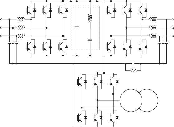
Cdc´ = 100 µF
Cr = 100 µF
Lr = 2.8 mH
Power rating-
200 V, 5 kVA
CNV. INV.Leav Linv
0.4 mH
0.4 mH
IN
OUT
25 µF
25 µF
10 µF
Zσc
Cdc´
Cr (6 w) Lr
Power maintaining time-
1 min
4Ω
IM
FW INV./CNV.
FW
Figure 9.11 Electrical diagram of double-conversion UPS with flywheel energy stor-
age, rating 5 kVA, 1 min [9.16].

Table 9.1 shows the major types of fuel cells considered for standby
and alternative electric power use. For applications that require frequent
and rapid start-ups, and where hydrogen and air are the available reac-
tants, a polymer-electrolyte membrane fuel cell (PEMFC) is the obvious
142 Chapter Nine
TABLE 9.1 Major Types of Fuel Cells. (Advantages vs. Disadvantages) [9.22]
Operating
Electrolyte temp. (C) Advantages Disadvantages
Polymer- 60–100 ■ Highest power density ■ Relatively expensive
electrolyte ■ Reduced corrosion catalysts required
membrane and electrolyte- ■ High sensitivity to fuel
fuel cell management problems impurities
(PEMFC) ■ Rapid start-up time
Alkaline 90–100 ■ High power density ■ High sensitivity to fuel
fuel cell ■ Demonstrated in impurities
(AFC) space applications ■ Intolerant to CO
2
Phosphoric 175–200 ■ High quality waste ■ Relatively expensive
acid fuel heat (for cogeneration catalysts required
cell (PAFC) applications) ■ Relatively low power
■ Demonstrated long life density
Molten 600–1000 ■ High quality waste heat ■ High temperature enhances
carbonate ■ Inexpensive catalysts corrosion and breakdown
fuel cell ■ Tolerant to fuel of all cell components
(MCFC) impurities ■ Relatively low power density
Solid 600–1000 ■ High quality waste heat ■ High temperature
oxide fuel ■ Inexpensive catalysts enhances corrosion and
cell (SOFC) ■ Tolerant to fuel breakdown of all cell
impurities components
■ Solid electrolyte ■ Sealing of stacks
[© 2004, IEEE, reprinted with permission]
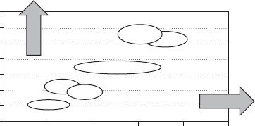
24000
Battery cost vs. capacity
per kW power output
20000
16000
12000
Cost ($)
8000
4000
0
010
Run time (hours)
20 30
Figure 9.12 Battery cost versus capacity per kW power
output. Acquisitions cost comparison for fuel cells and lead-
acid batteries in standby power applications. Battery cost-
diagonal shading. Fuel cell cost [9.21].
[© 2004, IEEE, reprinted with permission]
choice. PEMFC fuel cells also have the highest power density of all of
the types in Table 9.1 [9.22]. Fuel cells utilizing hydrogen as fuel can
operate for relatively long periods of time—for example, hours—or for
short periods, in standby service, in the nature of engine-generator sets
or batteries.
Applications. Specific applications include the following:
■
Space (used on Gemini, Apollo, and space shuttle missions)
■
As a UPS, which requires instant availability of power when utility
service fails. The fuel cell by itself requires heating to start up. UTC
Fuel Cells show a 5-kW UPS to supply 48 V dc for telecom applica-
tions, which uses ultracapacitors to supply the energy during the
start up of the fuel cell system.
■
The telecom industry is considering fuel cells as an alternative to VRLA
batteries for sites requiring 1 to 3 kW for up to eight hours [9.20–22].
■
Nakamoto, et al. show a 4.5-kW fuel cell system to produce 300 V ac
power, Figures 9-13 and 9-14 [9.23].
■
Utility industry applications include a study by Sedghisigarchi and
Feliachi of 1.5-MW fuel cell systems and gas-turbine generators oper-
ating on a common bus in a 9-MW system [9.24].
Uninterruptible Power Supplies 143
H
2
H
2
H
2
Fuel line
Hydrogen
cylinder
box.
Hydrogen cylinder
Air
Exhaust fan
Exhaust
gas
Fuel cell
Fan
Water
Water
vessel
Inverter
Charger
BatteryControl unit
Operation
panel
AC
100 V
Hydrogen
sensor
Power line Control line
Water control line
Generation unit
Fuel electrode
Electrolyte
Air electrode
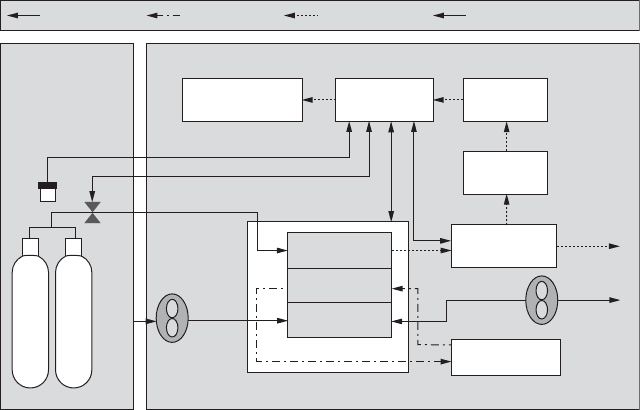
Figure 9.13 Block diagram of 4.5-kW fuel cell UPS [9.23].
[© 2000, IEEE, reprinted with permission]
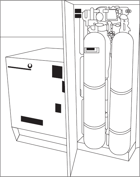
NTWED
Figure 9.14 External appearance of 4.5-kW fuel cell UPS [9.23].
[© 2000, IEEE, reprinted with permission]
Ultracapacitors
Ultracapacitors can substitute for batteries in low-power UPS. Their fea-
tures include
■
Construction: These capacitors utilize electrodes of highly porous
carbon to achieve large values of capacitance per unit weight. Zorpetta
quotes surface area of 1500 m
2
/g; a typical electrode of 250 g would
have an area of 375,000 m
2
[9.25].
■
Ratings: Maxwell Technologies offers ultracapacitors ranging from
5 to 10 F to cylindrical 2700 F, rated 2.5 V DC per cell [9.26]. Storage
amounts to 3 or 4 Wh/kg [9.25].
■
Applications: One manufacturer offers UPS modules rated 1.6 and
2.3 kW, replacing batteries, employing 2300 F of ultracapacitors [9.27].
M. L. Perry describes a 5-kW fuel cell standby power unit in which
three banks of ultracapacitors provide the energy while the fuel cells
144 Chapter Nine