Peng S., Zhang J., Engineering Geology for Underground Rocks
Подождите немного. Документ загружается.

9.3 Case studies 235
0
35
94
112
180
0
25 50 75 100 125 150 175 200
90
65
1
4
7
10
13
16
19
22
1
4
7
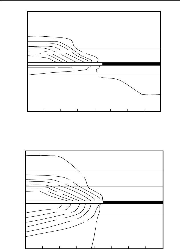
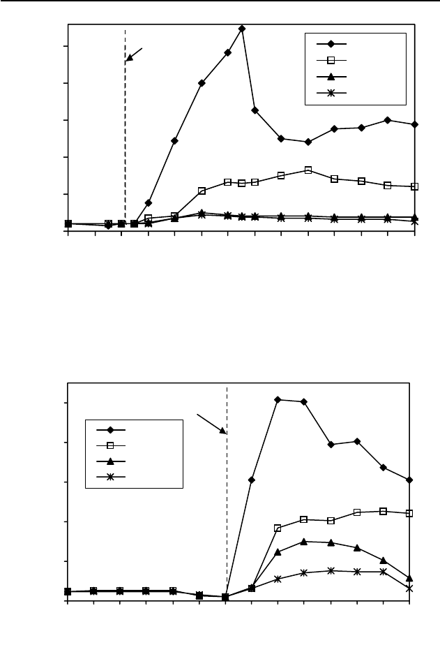
Fig. 9.12. Variations of hydraulic conductivity in the vertical direction for the
mining width of 220 m.
0
35
94
112
180
0
25 50 75 100 125 150 175 200
90
65
1
4
7
10
13
16
19
22
1
19
16
13
10
7
4
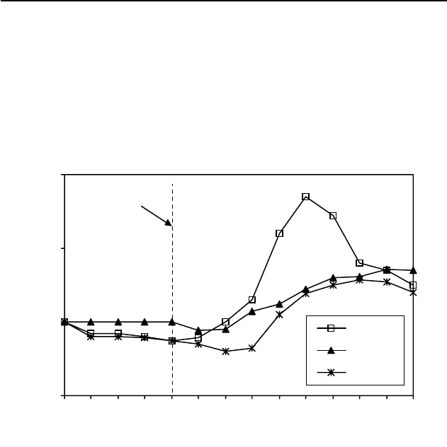
Fig. 9.13. Variations of hydraulic conductivity in the horizontal direction for the
mining width of 220 m.

236 9 Strata failure and mining under surface and ground water
Lab simulation using physical models
Physical simulation by using a similarity model was conducted to verify
the foregoing numerical calculations, particularly the height of the strata
fractured zone, which is the most critical criterion for design of mining un-
der aquifers. The model was built in layers by using a mixture of water,
fine-grained sand, and gypsum, with different mass proportions to simulate
the strata with different strengths. The joints between layers and within
each layer were made and filled with micas. The model measured 240 cm
in length by 156 cm in height and 20 cm in width. The geometry ratio of
the simulation model to the in-situ panel was C = 1:100, i.e., 1 cm in the
model is equal to 1 m in the prototype. The bulk densities of the strata in
the prototype and the simulated materials were 2,500 and 1,600 kg/m
3
, re-
spectively. Therefore, all the related simulation constants were as follows:
x for bulk density: C
J
=1600/2500 = 0.64;
x for strength and stress: C
V
=CC
J
= 0.0064;
x for loading: C
F
= C
3
C
J
= 6.4×10
-7
;
x for time: C
t
= C
0.5
= 0.1.
Displacement gauges and stress sensors in both vertical and horizon-
tal directions were installed to study the stress distribution, strata deforma-
tion and failure induced by seam extraction. In this physical model, the
simulation height of the overburden was 90 m, including 35 m of uncon-
solidated alluvium and 55 m of roof strata, the thickness of the underbur-
den was 62 m, and the thickness of the extraction seam was 4 m. Three
models were conducted and extracted repeatedly for mining with full cav-
ing to ensure accuracy and one other model was constructed to model min-
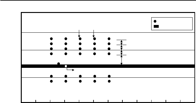
ing with partial sand backfilling. Figure 9.14 presents the model geometry
and locations of stress sensors. The six horizontal layers of stress cells
along five vertical sections were installed in different heights: four layers
in the roof and two layers in the floor.
The extraction was simulated by cutting the seam from left to right
(Fig. 9.14) in intervals of 5 cm. During the extraction 60 cm of pillar was
left in the left side and 50 cm in the right side to avoid boundary effects.
The roof failure, stress and displacement were measured and recorded for
each cutting step as advance of seam extraction.
9.3 Case studies 237
0
35
94
156
0
20 40 60 80 100 120 140 160
112
65
90
180 200 220 240
Direction of advance
456
910
11
1514
16
19 20 21
16 cm
10 cm
10 cm
9 cm
Stress sensors
Coal seam
4
Distance (cm)
H
e
i
g
h
t
(
c
m
)
3
8
13
18
1
2
7
12
17
Section III Section IV
Fig. 9.14. A plan view of the simulation model showing the locations of stress
sensors (1 cm in the model = 1 m in the prototype).
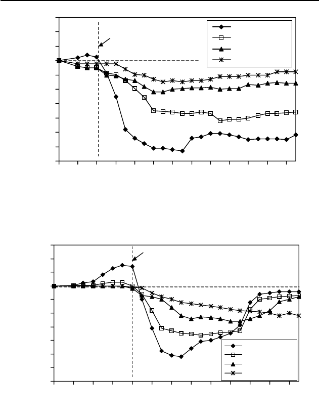
Figure 9.15 shows the vertical stress increments (the difference be-
tween the induced and origin stresses) in Section III located 20 m away in
the direction of advance from the starting cut (refer to Fig. 9.14). It can be
seen that only one stress increment in the four sensors increases (so called
abutment pressure) before the mining face approaches the sensor located
closest to the coal seam. After the face passes the sensors, the stress incre-
ments in all four sensors decrease gradually, i.e. the strata experience a
state of unloading in which the induced fractures developed easily (Zhang
and Shen 2004). This phenomenon is more pronounced for the strata closer
to the seam. Figure 9.16 shows the vertical stress increments in Section IV
located 40 m in front of the starting cut (see Fig. 9.14). The abutment pres-
sures exist in all four sensors before the face advances through the ob-
served section. These higher stresses are caused by the transfer of the
weight of the overburden roof strata in the excavated area to the solid coal
in front and on both sides of the face and to the broken strata behind the
face. After the strata in the observed section lie in the extracted area, the
stress redistribution, as advance of the extraction, experiences three stages,
i.e. dramatic decrease and gentle reduction, and gradual recovery to the
origin stress.
238 9 Strata failure and mining under surface and ground water
-3.5
-3.0
-2.5
-2.0
-1.5
-1.0
-0.5
0.0
0.5
1.0
1.5
0 102030405060708090100110120
Distance of advance (cm)
Stress increment (MPa)
C4: h=16 cm
C9: h=26 cm
C14: h=36 cm
C19: h=45 cm
Location of stress sensors
Fig. 9.15. Observed vertical stress increment for a section with the stress sensors
located 20 cm from the starting cut (1 cm in the model = 1 m in the prototype).
-3.5
-3.0
-2.5
-2.0
-1.5
-1.0
-0.5
0.0
0.5
1.0
1.5
0 102030405060708090100110120
Distance of advance (cm)
Stress increment (MPa)
C5: h=16 cm
C10: h=26 cm
C15: h=36 cm
C20: h=45 cm
Location of stress sensors
Fig. 9.16. Observed vertical stress increment for a section with the stress sensors
located 40 cm from the starting cut (1 cm in the model = 1 m in the prototype).
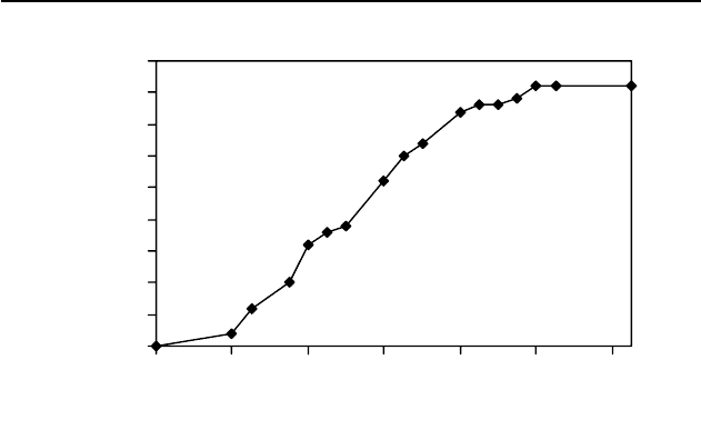
The strata fractured zone was recorded during the seam extraction.
Figure 9.17 plots the observed height of the fractured zone with the dis-
tance of advance of the extraction. It shows that the height of the fractured
strata increases gradually with extraction until reaching a maximum of 41
m as the face advances 100 m.
9.3 Case studies 239
0
5
10
15
20
25
30
35
40
45
0 20 40 60 80 100 120
Distance of advance (cm)
Height of fractured zone (cm)
Fig. 9.17. Observed development of the fractured zone with advance of the seam
extraction (1 cm in the model = 1 m in the prototype).
The changes of hydraulic conductivity due to stress redistribution
were calculated by Eq. 9.9 according to the observed vertical and horizon-
tal stresses in the physical models. Only the vertical conductivity ratio
(K/K
0
, post- to pre-mining conductivities) was considered in this case. Fig-
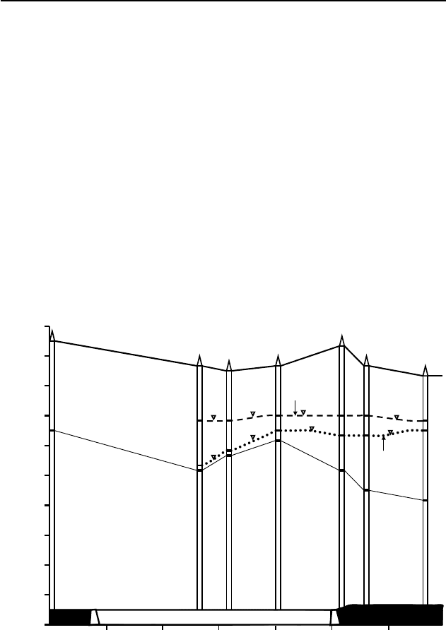
ure 9.18 presents the conductivity ratio in a section of the strata located 20
m in front of the starting cut (Zhang and Shen 2004). It is observed that the
conductivity is basically unchanged before the face reaches the studied
section. For the strata located 16 and 26 m above the seam, after the face
passes the section (the strata lie in the mined area), the conductivities in-
crease considerably; as the conductivities reach maximum magnitudes
(such as K/K
0
= 27.4, when h = 16 m), the increases slow down. For the
strata located 36 and 45 m over the seam, after the face passes the section,
the conductivities only have very small increases (such as, the maximum
K/K
0
= 2.5 for h = 36 m). Figure 10.19 plots the conductivity ratio in a sec-
tion of the strata located 60 m in front of the starting cut. Comparing Fig.
10.19 to Fig. 9.18 it can be seen that the conductivity changes have same
trend except that Fig. 9.19 has a smaller magnitude for the strata located 16
and 26 m above the seam after the strata lie in the mined area. This is due
to the fact that the studied strata in Fig. 9.18 are closer to the abutment area
where a larger stress change prevails. It is also observed from Figs. 9.18
and 9.19 that the conductivity only has a very small variation when the
strata lie 45 m above the extracted seam.
240 9 Strata failure and mining under surface and ground water
0
5
10
15
20
25
0 102030405060708090100110120130
Distance of advance (m)
K/K
0
h=16 m
h=26 m
h=36 m
h=45 m
Strata section
Fig. 9.18. Calculated hydraulic conductivity ratios for a section with the strata
located 20 m from the starting cut.
0
4
8
12
16
20
0 102030405060708090100110120130
Distance of advance (m)
K/K
0
h=16 m
h=26 m
h=36 m
h=45 m
Strata section
Fig. 9.19. Calculated hydraulic conductivity ratios for a section with the strata lo-
cated 60 m from the starting cut.
9.3 Case studies 241
When the mined area is backfilled, the stress changes are greatly re-
duced. Figure 9.20 gives the conductivity change in a physical model in
which the extracted area was backfilled partially 30 m from the cut with
sands. Compared to the full caving extraction in Figs. 9.18 and 9.19, the
conductivity in the partially backfilled case as shown in Fig. 9.20 has very
small changes after mining. This indicates that the mining operation will
be much safer for mining with backfilling, when aquifers are near the min-
ing workings.
0
1
2
3
0102030405060708090100110120130
Distance of advance (m)
K/K
0
h=26 m
h=36 m
h=45 m
Strata section
Fig. 9.20. Calculated hydraulic conductivity ratios for a section with the strata lo-
cated 40 m from the starting cut, for the extraction with partial backfilling.
Field monitoring in Face 102
Summarizing the numerical calculation and physical simulation, the height
of the strata failure zone ranges from 41 to 42.5 m, and the height of the
conductivity enhancement zone in the vertical direction varies from 45 to
46.2 m. Furthermore, from the empirical formula (Eq. 9.2) it can be ob-
tained that for the strata with medium strength the maximum height of the
water-conducting fractured zone is 45.6 m. According to the above results,
it can be concluded that disastrous water inrush would not occur when the
distance between the aquifer and coal seam is greater than 46.2 m. There-
fore, the old design for Face 102 was revised and the location of the start-
ing cut was changed, as shown in Fig. 9.21, since the strata thickness was

242 9 Strata failure and mining under surface and ground water
less than 46.2 m around the old location.
Face 201
borehole
N
O
l
d
s
t
a
r
t
i
n
g
c
u
t
N
e
w
s
t
a
r
t
i
n
g
c
u
t
Direction of advance
Tailgate
Maingate
W2
W8 W9
W12
G3
G2
G1
W5
W7
A
B
50 m
W6
Fig. 9.21. A plan view for mining panel Face 102 that shows the location of ob-
serving boreholes.
In order to secure the mining operation, several boreholes (refer to
Fig. 9.21) were drilled to monitor the changes of the water table in pre- and
post-mining. The boreholes were located near the new starting cut, since
the thickness of the covering strata in this area was the smallest in this
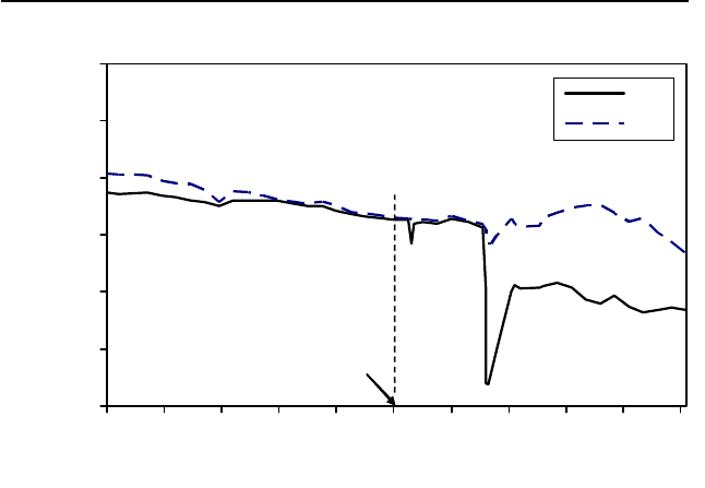
panel (Zhang and Shen 2004). Figure 9.22 shows the geologic section of
the face around the new cut. Note that the shortest distance between the
aquifer and the mining workings was 46.73 m, located in borehole W2.
Therefore, this was the key location needed to be monitored. Figure 9.23
records the changes of water tables in boreholes W2 and G3 pre- and post-
mining. The starting time of seam extraction in Face 201 was July 10. Be-
fore the extraction, the water tables in boreholes W2 and G3 lowered
slightly, as shown in Fig. 9.24. On July 16 when Face 102 advanced 10 m
(the face just passed borehole W2), the water table in this hole lowered
moderately, illustrating that the strata conductivity increased in this area.
On August 11 when Face 102 advanced 60 m (the face passed borehole
W2 50 m), the water table in W2 dropped dramatically. The water table in
9.3 Case studies 243
W2 decreased 11.18 m, relative to that 2.5 hrs earlier. However, the water
table in the adjacent borehole G3 and other holes only had small fluctua-
tions (refer to Figs. 9.22 and 9.23). These indicate that the strata conductiv-
ity had a great enhancement in the strata located 46.73m high (hole W2)
from the seam, but no obvious increase in the strata located 51.95 m away
from the seam (hole G3). Later, the water table in W2 increased gradually.
However, it could not recover to the pre-mining level. The water table
variation in W2 induced by the hydraulic conductivity change verifies the
previous calculated results shown in Figs. 9.18 and 9.19. That is, the post-
mining conductivity increases gradually, then reaches a maximum after a
certain distance (20 to 60 m), and finally decreases to a certain value.
Since the minimum strata thickness in Face 102 was strictly controlled and
was not allowed to be less than the calculated value, 46.2 m, the seam was
successfully extracted and 2,825 thousand tons of coal reserve was recov-
ered with neither water inrush nor even excessive groundwater discharge
to the workings.
1230
1140
1150
1160
1170
1180
1190
1200
0
50 100 150 200 250 350300
Distance (m)
1210
1220
1240
E
l
e
v
a
t
i
o
n
(
m
)
Surface
Bedrock
Aquifer
W8
W2
W12
G3
W6
W5
G2
Face 102
Pre-mining
water table
Post-mining
water table
1192.36
1197.58
1201.03
1192.52
1185.74
1181.8
4
1145.63
1146.9
1204.29
Fig. 9.22. The A-B section in Fig. 9.21 illustrating the aquifer location, pre-
mining water table and the maximum water table drop induced by mining.
244 9 Strata failure and mining under surface and ground water
1190
1195
1200
1205
1210
1215
1220
4/1 4/21 5/11 5/31 6/20 7/10 7/30 8/19 9/8 9/28 10/18
Time (month/day)
Water table (m)
W2
G3
Mining started
Fig. 9.23. Changes of water tables (elevations from the sea level) pre- and post-
mining in observing boreholes of W2 and G3.
9.4 Mining under bodies of water at shallow depths
9.4.1 Introduction
To enhance recovery, it is often necessary to extract coal seams in very dif-
ficult geological and hydrogeological conditions and at shallow and deep
depths (Peng et al. 2002b). However, in some cases coal production, envi-
ronment, and lives of miners have suffered serious threats from water in-
rushes, methane explosions and roof collapses. In a considerable number
of coalfields in China the coal beds are covered by unconsolidated Ceno-
zoic alluvium, such as those in the Yellow river and the Huai river alluvial
plain areas. The alluvium is comprised of mixed impermeable clay layers
with water-bearing sands and gravels. Usually, the lowermost layer in the
alluvium is permeable water-bearing sands mixed with gravels. Underlying
the aquifer is the bedrock of coal beds. The water-bearing layers, particu-
larly the lowermost aquifers, are potential threats to safe mining at shallow
depth. In China, water inrush incidents happen frequently during mining at
