Nof S.Y. Springer Handbook of Automation
Подождите немного. Документ загружается.

Control of Uncertain Systems 11.3 Variable-Structure Neural Component 205
x
2
x
1
ξ
RC
(x)
1
0.8
0.6
0.4
0.2
0
2
1
0
–1
–2
–2
0
2
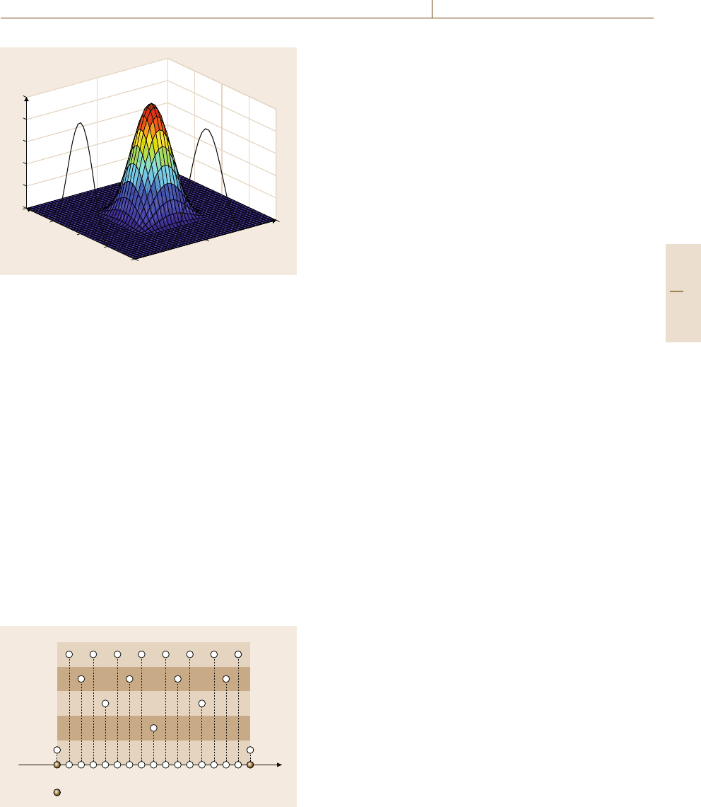
Fig. 11.3 Plot of a two-dimensional (2-D) raised-cosine ra-
dial basis function
11.3.1 Center Grid
Recall that the unknown functions are approximated
over a compact set Ω
x
⊂R
n
.ItisassumedthatΩ
x
can
be represented as
Ω
x
=
x ∈R
n
: x
l
≤ x ≤ x
u
(11.18)
=
x ∈R
n
: x
li
≤ x
i
≤ x
ui
, 1 ≤i ≤ n
, (11.19)
where the n-dimensional vectors x
l
and x
u
denote lower
and upper bounds of x, respectively. To locate the cen-
ters of RBFs inside the approximation region Ω
x
,an
n-dimensional center grid with layer hierarchy is uti-
lized, where each grid node corresponds to the center of
one RBF. The center grid is initialized with its nodes
located at (x
l1
, x
u1
)×(x
l2
, x
u2
)×···×(x
ln
, x
un
), where
× denotes the Cartesian product. The 2
n
grid nodes of
the initial center grid are referred to as boundary grid
Potential grids nodes
Boundary nodes
Layer
5
4
3
2
1
Fig. 11.4 Example of determining potential grid nodes in
one coordinate
nodes and cannot be removed. Additional grid nodes
will be added and then can be removed within this
initial grid as the controlled system evolves in time.
The centers of new RBFs can only be placed at the
potential locations. The potential grid nodes are deter-
mined coordinate-wise. In each coordinate,the potential
grid nodes of the first layer are the two fixed bound-
ary grid nodes. The second layer has only one potential
grid node in the middle of the boundary grid nodes.
Then the potential grid nodes of the subsequent lay-
ers are in the middle of the adjacent potential grid
nodes of all the previous layers. The determination
of potential grid nodes in one coordinate is illustrated
in Fig.11.4.
11.3.2 Adding RBFs
As the controlled system evolves in time, the out-
put tracking error e is measured. If the magnitude of
e exceeds a predetermined threshold e
max
, and if the
dwelling time of the current network structure has been
greater than the prescribed T
d
, the network tries to add
new RBFs at potential grid nodes, that is, add new grid
nodes. First, the nearest-neighboring grid node, denoted
c
(nearest)
, to the current input x is located among existing
grid nodes. Then the nearer-neighboring grid node de-
noted c
(nearer)
is located, where c
i(nearer)
is determined
such that x
i
is between c
i(nearest)
and c
i(nearer)
.Next,
the adding operation is performed for each coordinate
independently.
In the i-th coordinate, if the distance between x
i
and c
i(nearest)
is smaller than a prescribed threshold
d
i(threshold)
or smaller than a quarter of the distance
between c
i(nearest)
and c
i(nearer)
, no new grid node is
added in the i-th coordinate. Otherwise, a new grid
node located at half of the sum of c
i(nearest)
and c
i(nearer)
is added in the i-th coordinate. The design parameter
d
i(threshold)
specifies the minimum grid distance in the i-
th coordinate. The above procedures for adding RBFs
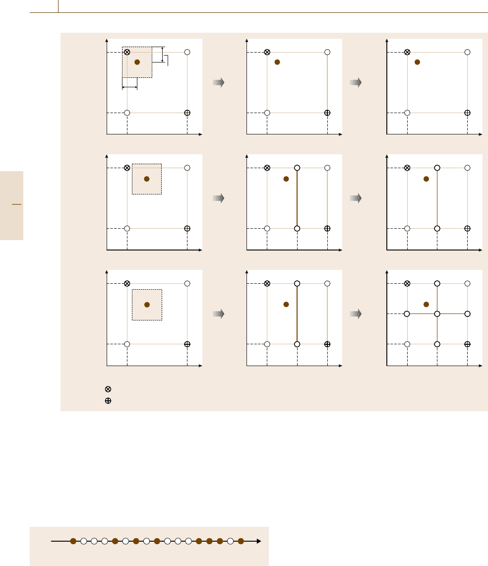
are illustrated with two-dimensional examples shown
in Fig. 11.5. In case 1, no RBFs are added. In case 2,
new grid nodes are added out of the first coordinate. In
case 3, new grid nodes are added out of both coordi-
nates. In summary, a new grid node is added in the i-th
coordinate if the following conditions are satisfied:
1. |e| > e
max
.
2. The elapsed time since last operation, adding or re-
moving, is greater than T
d
.
3.
x
i
−c
i(nearest)
> max
c
i(nearest)
−c
i(nearer)
/4, d
i(threshold)
.
Part B 11.3
206 Part B Automation Theory and Scientific Foundations
Case 1
c
2(nearest)
c
2(nearer)
c
1(nearer)
c
1(nearest)
d
1(threshold)
d
2(threshold)
c
2(nearest)
c
2(nearer)
c
1(nearer)
c
1(nearest)
c
2(nearest)
c
2(nearer)
c
1(nearer)
c
1(nearest)
Case 2
c
2(nearest)
c
2(nearer)
c
1(nearer)
c
1(nearest)
c
2(nearest)
c
2(nearer)
c
1(nearer)
c
1(nearest)
Case 3
The nearest-neighboring center c
(nearest)
The nearer-neighboring center c
(nearer)
c
2(nearest)
c
2(nearer)
c
1(nearer)
c
1(nearest)
c
2(nearest)
c
2(nearer)
c
1(nearer)
c
1(nearest)
New RBFs
out of first
coordinate
New RBFs
out of first
coordinate
No new RBFs
out of first
coordinate
c
2(nearest)
c
2(nearer)
c
1(nearer)
c
1(nearest)
No new
RBFs out of
second coordinate
No new RBFs
out of second
coordinate
c
2(nearest)
c
2(nearer)
c
1(nearer)
c
1(nearest)
New RBFs
out of
second
coordinate
Fig. 11.5 Two-dimensional examples of adding RBFs
The layer of the i-th coordinate assigned to the newly
added grid node is one level higher than the highest
layer of the two adjacent existing grid nodes in the same
coordinate. A possiblescenario of formationof the layer
hierarchy in one coordinate is shown in Fig.11.6. The
white circles denote potential grid nodes, and the black
circles stand for existing grid nodes. The number in
Layer No.1 5 4 5 3 5 4 5 2 5 4 5 3 5 4 5 1
13524761
Fig. 11.6 Example of formation of the layer hierarchy in one coor-
dinate
the black circles shows the order in which the corre-
sponding grid node is added. The two black circles with
number 1 are the initial grid nodes in this coordinate,
so they are in the first layer. Suppose the adding oper-
ation is being implemented in this coordinate after the
grid initialization. Then a new grid node is added in the
middle of two boundary nodes 1 – see the black cir-
cle with number 2 in Fig.11.6. This new grid node is
assigned to thesecond layer becauseof theresulting res-
olution it yields. Then all the following grid nodes are
added one by one. Note that nodes 3 and 4 belong to the
same third layer because they yield the same resolution.
On the other hand, node 5 belongs to the fourth layer
because it yields higher resolution than nodes 2 and 3.
Part B 11.3
Control of Uncertain Systems 11.3 Variable-Structure Neural Component 207
Nodes 6 and 7 are assigned to their layers in a similar
fashion.
11.3.3 Removing RBFs
When the magnitude of the output tracking error e
falls within the predetermined threshold e
max
and the
dwelling-time requirement has been satisfied, the net-
work attempts to remove some of the existing RBFs,
that is, some of the existing grid nodes, in order to avoid
1
2
1
Layer No. 1 2 1
1
2
1
Layer No.
Remove RBFs
out of first
coordinate
RBFs not removed
out of first coordinate
Remove RBFs
out of first coordinate
Remove RBFs
out of
second
coordinate
RBFs not removed
out of second
coordinate
Remove RBFs
out of second
coordinate
1
Case 1: All conditions are satisfied for both coordinates
1
1
2
1
Layer No. 1 1
1
2
1
Layer No. 1 2 1
1
2
1
Layer No. 1
Case 2: The third condition is not satisfied for the first coordinate
1
1
2
1
Layer No. 1 1
1
2
1
Layer No. 1
333
21
1
2
1
Layer No. 1
Case 3: The fourth condition is not satisfied for the second coordinate
1
1
2
1
Layer No. 1 1
The nearest-neighboring center c
(nearest)
The gride node in the i-th coordinate with its i-th coordinate to be c
i(nearest)
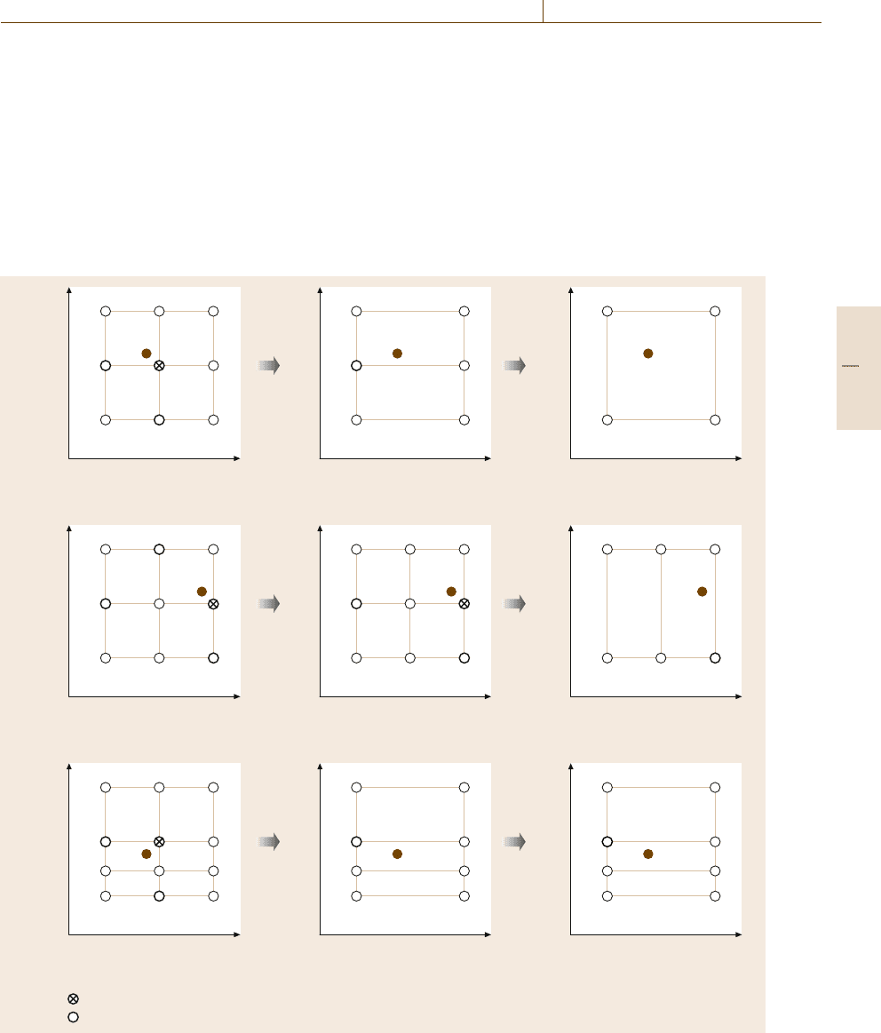
Fig. 11.7 Two-dimensional examples of removing RBFs
network redundancy. The RBF removing operation is
also implemented for each coordinate independently. If
c
i(nearest)
is equal to x
li
or x
ui
, then no grid node is
removed from the i-th coordinate. Otherwise, the grid
node located at c
i(nearest)
is removed from the i-th coor-
dinate if this grid node is in the higher than or in the
same layer as the highest layer of the two neighbor-
ing grid nodes in the same coordinate, and the distance
between x
i
and c
i(nearest)
is smaller than a fraction τ
of the distance between c
i(nearest)
and c
i(nearer)
, where
Part B 11.3

208 Part B Automation Theory and Scientific Foundations
the fraction τ is a design parameter between 0 and 0.5.
The above conditionsfor the removing operation to take
place in the i-th coordinate can be summarized as:
1. |e|≤e
max
.
2. The elapsed time since last operation, adding or re-
moving, is greater than T
d
.
3. c
i(nearest)
/∈
x
li
, x
ui
.
4. The grid node in the i-th coordinate with its coordi-
nate equal to c
i(nearest)
is in a higher than or in the
same layer as the highest layer of the two neighbor-
ing grid nodes in the same coordinate.
5.
x
i
−c
i(nearest)
<τ
c
i(nearest)
−c
i(nearer)
, τ ∈(0, 0.5).
Two-dimensional examples of removing RBFs are illus-
trated in Fig.11.7, where the conditions (1), (2), and (5)
are assumed to be satisfied for both coordinates.
11.3.4 Uniform Grid Transformation
The determination of the radius of the RBF is much eas-
ier in a uniform grid than in a nonuniform grid because
the RBF is radially symmetric with respect to its cen-
ter. Unfortunately, the center grid used to locate RBFs
is usually nonuniform. Moreover, the structure of the
center grid changes after each adding or removing oper-
ation, which further complicates the problem. In order
to simplify the determination of the radius, the one-
to-one mapping z(x) =[z
1
(x
1
), z
2
(x
2
),...,z
n
(x
n
)]
,
proposed in [11.60], is used to transform the center grid
into a uniform grid. Suppose that the self-organizing
RBF network is now with the v-th admissible struc-
ture after the adding or removing operation and
there are M
i,v
distinct elements in S
i
, ordered as
c
i(1)
< c
i(2)
< ···< c
i(M
i,v
)
, where c
i(k)
is the k-th el-
ement with c
i(1)
= x
li
and c
i(M
i,v
)
= x
ui
. Then the
mapping function z
i
(x
i
) :[x
li
, x
ui
]→[1, M
i,v
]takes the
following form:
z
i
(x
i
) =k+
x
i
−c
i(k)
c
i(k+1)
−c
i(k)
, c
i(k)
≤ x
i
< c
i(k+1)
,
(11.20)
which maps c
i(k)
into the integer k. Thus, the transfor-
mation z(x) :Ω
x
→R
n
maps the center grid into a grid
with unit spacing between adjacent grid nodes such that
the radius of the RBF can be easily chosen. For the
raised-cosine RBF, the radius in every coordinate is se-
lected to be equal to one unit, that is, the radius will
touch but not extend beyond the neighboring grid nodes
in the uniform grid. This particular choice of the ra-
dius guarantees that for a given input x, the number of
nonzero raised-cosine RBFs in the uniform grid is at
most 2
n
.
To simplify the implementation, it is helpful to
reorder the M
v
grid nodes into a one-dimensional ar-
ray of points using a scalar index j. Let the vector
q
v
∈ R
n
be the index vector of the grid nodes, where
q
v
= (q
1,v
,...,q
n,v
)
with 1 ≤q
i,v
≤ M
i,v
. Then the
scalar index j can be uniquely determined by the index
vector q
v
, where
j =(q
n,v
−1)M
n−1,v
···M
2,v
M
1,v
+···
+(q
3,v
−1)M
2,v
M
1,v
+(q
2,v
−1)M
1,v
+q
1,v
.
(11.21)
Let c
j,v
=(c
1j,v
,...,c
nj,v
)
denote the location of the
q
v
-th grid node in the original grid. Then the corre-
sponding grid node in the uniform grid is located at
z
j,v
= z(c
j,v
) =(q
1,v
,...,q
n,v
)
. Using the scalar in-
dex j in (11.21), the output
ˆ
f
i,v
(x) ofthe self-organizing
raised-cosine RBF network implemented in the uniform
grid can be expressed as
ˆ
f
v
(x) =
M
v
j=1
ω
fj,v
ξ
j,v
(x)
=
M
v
j=1
ω
fj,v
n
#
i=1
ψ
z
i
(x
i
)−q
i,v
,
(11.22)
where the radius is one unit in each coordinate.
When implementing the output feedback controller,
the state vector estimate
ˆ
x is used rather than the actual
state vector x. Itmay happen that
ˆ
x /∈Ω
x
. In such a case,
the definition of the transformation (11.20) is extended
as
⎧
⎨
⎩
z
i
(
ˆ
x
i
) =1if
ˆ
x
i
< c
i(1)
z
i
(
ˆ
x
i
) = M
i,v
if
ˆ
x
i
> c
i(M
i,v
)
,
(11.23)
for i =1, 2,...,n.If
ˆ
x ∈Ω
x
, the transformation(11.20)
is used. Therefore, it follows from (11.20)and(11.23)
that the function z(x) maps the whole n-dimensional
space
R
n
into the compact set [1, M
1,v
]×[1, M
2,v
]×
···×[1, M
n,v
].
11.3.5 Remarks
1. The internal structure of the self-organizing RBF
networkvaries as theoutput trackingerror trajectory
evolves. When the output tracking error is large, the
network adds RBFs in order to achieve better model
compensation so that the large output tracking error
Part B 11.3

Control of Uncertain Systems 11.4 State Feedback Controller Development 209
can be reduced. When, on the other hand, the output
tracking error is small, the network removes RBFs
in order to avoid a redundant structure. If the design
parameter e
max
is too large, the network may stop
adding RBFs prematurely or even never adjust its
structure at all. Thus, e
max
should be at least smaller
than |e(t
0
)|.However,ife
max
is too small, the net-
work may keep adding and removing RBFs all the
time and cannot approach a steady structure even
though the output tracking error is already within
the acceptable bound. In the worst case, the network
will try to add RBFs forever. This, of course, leads
to an unnecessary large network size and, at the
same time, undesirable high computational cost. An
appropriate e
max
may be chosen by trial and error
through numerical simulations.
2. The advantage of the raised-cosine RBF over the
Gaussian RBF is the property of the compact sup-
port associated with the raised-cosine RBF. The
number of terms in (11.22) grows rapidly with the
increase of both the number of grid nodes M
i
in
each coordinate and the dimensionality n of the in-
put space. For the GRBF network, all the terms
will be nonzero due to the unbounded support,
even though most of them are quite small. Thus,
a lot of computations are required for the net-
work’s output evaluation, which is impractical for
real-time applications, especially for higher-order
systems. However, for the RCRBF network, most
of the terms in (11.22) are zero and therefore do not
have to be evaluated. Specifically, for a given in-
put x, the number of nonzero raised-cosine RBFs
in each coordinate is either one or two. Conse-
quently, the number of nonzero terms in (11.22)
is at most 2
n
. This feature allows one to speed up
the output evaluation of the network in compari-
son with a direct computation of (11.22)forthe
GRBF network. To illustrate the above discussion,
suppose M
i
=10 and n = 4. Then the GRBF net-
work will require 10
4
function evaluations, whereas
the RCRBF network will only require 2
4
func-
tion evaluations, which is almost three orders of
magnitude less than that required by the GRBF
network. For a larger value of n and a finer grid,
the saving of computations is even more dramatic.
The same saving is also achieved for the network’s
training. When the weights of the RCRBF net-
work are updated, there are also only 2
n
weights
to be updated for each output neuron, whereas
n × M weights has to be updated for the GRBF
network. Similar observations were also reported
in [11.60,p.6].
11.4 State Feedback Controller Development
The direct adaptive robust state feedback controller pre-
sented in this chapter has the form
u = u
a,v
+u
s,v
=
1
ˆ
g
v
(x)
−
ˆ
f
v
(x)+y
(n)
d
−ke
+u
s,v
, (11.24)
where
ˆ
f
v
(x) =ω
f,v
ξ
v
(x),
ˆ
g
v
(x) =ω
g,v
ξ
v
(x)andu
s,v
is
the robustifying component to be described later. To
proceed, let Ω
e
0
denote the compact set including all
the possible initial tracking errors and let
c
e
0
= max
e∈Ω
e
0
1
2
e
P
m
e , (11.25)
where P
m
is the positive-definite solution to the con-
tinuous Lyapunov matrix equation A
m
P
m
+P
m
A
m
=
−2Q
m
for Q
m
=Q
m
> 0. Choose c
e
> c
e
0
and let
Ω
e
=
e :
1
2
e
P
m
e ≤c
e
.
(11.26)
Then the compact set Ω
x
is defined as
Ω
x
=
x : x =e+x
d
, e ∈Ω
e
, x
d
∈Ω
x
d
,
over which the unknown functions f(x)andg(x) are
approximated.
For practical implementation, ω
f,v
and ω
g,v
are con-
strained, respectively, to resideinside compact sets Ω
f,v
and Ω
g,v
defined as
Ω
f,v
=
ω
f,v
:ω
f
≤ω
fj,v
≤ω
f
, 1 ≤ j ≤ M
v
(11.27)
and
Ω
g,v
=
ω
g,v
:0<ω
g
≤ω
gj,v
≤ω
g
, 1 ≤ j ≤ M
v
,
(11.28)
where ω
f
, ω
f
, ω
g
and ω
g
are design parameters.
Let ω
∗
f,v
and ω
∗
g,v
denote the optimal constant weight
vectors corresponding to each admissible network
Part B 11.4

210 Part B Automation Theory and Scientific Foundations
structure, which are used only in the analytical analysis
and defined, respectively, as
ω
∗
f,v
= argmin
ω
f,v
∈Ω
f,v
max
x∈Ω
x
f(x)−ω
f,v
ξ
v
(x)
(11.29)
and
ω
∗
g,v
= argmin
ω
g,v
∈Ω
g,v
max
x∈Ω
x
g(x)−ω
g,v
ξ
v
(x)
.
(11.30)
For the controller implementation, let
d
f
=max
v
max
x∈Ω
x
f(x)−ω
∗
f,v
ξ
v
(x)
(11.31)
and
d
g
=max
v
max
x∈Ω
x
g(x)−ω
∗
g,v
ξ
v
(x)
,
(11.32)
where max
v
(·) denotes the maximization taken over all
admissible structures of the self-organizing RBF net-
works. Let φ
f,v
=ω
f,v
−ω
∗
f,v
and φ
g,v
=ω
g,v
−ω
∗
g,v
,
and let
c
f
=max
v
max
ω
f,v
,ω
∗
f,v
∈Ω
f,v
1
2η
f
φ
f,v
φ
f,v
(11.33)
and
c
g
=max
v
max
ω
g,v
,ω
∗
g,v
∈Ω
g,v
1
2η
g
φ
g,v
φ
g,v
,
(11.34)
where η
f
and η
g
are positive design parameters of-
ten referred to as learning rates. It is obvious that
c
f
(or c
g
) will decrease as η
f
(or η
g
) increases. Let
σ = b
P
m
e. The following weight vector adaptation
laws are employed, respectively, for the weight vectors
ω
f
and ω
g
,
˙
ω
f,v
=Proj
ω
f,v
,η
f
σξ
v
(x)
(11.35)
and
˙
ω
g,v
=Proj
ω
g,v
,η
g
σξ
v
(x)u
a,v
,
(11.36)
where Proj(ω
v
, θ
v
) denotes Proj(ω
j,v
, θ
j,v
)forj =
1,...,M
v
and
Proj(ω
j,v
, θ
j,v
) =
⎧
⎪
⎪
⎨
⎪
⎪
⎩
0ifω
j,v
=ω and θ
j,v
< 0 ,
0ifω
j,v
=ω and θ
j,v
> 0 ,
θ
j,v
otherwise ,
(11.37)
is a discontinuous projection operator proposed
in [11.65]. The robustifying component u
s,v
is designed
as
u
s,v
=−
1
g
k
s,v
sat
σ
ν
,
(11.38)
where k
s,v
=d
f
+d
g
|u
a,v
|+d
0
and sat(·) is the satura-
tion function with small ν>0. Let
k
s
=d
f
+d
g
max
v
max|u
a,v
|
+d
0
, (11.39)
where theinner maximizationis taken over e ∈Ω
e
, x
d
∈
Ω
x
d
, y
(n)
d
∈Ω
y
d
, ω
f,v
∈Ω
f,v
,andω
g,v
∈Ω
g,v
.
It can be shown [11.58] that, for the plant (11.2)
driven by the proposed direct adaptive robust state feed-
back controller (DARSFC)(11.24) with the robustify-
ing component (11.38) and the adaptation laws (11.35)
and (11.36), if one of the following conditions is
satisfied:
•
The dwelling time T
d
of the self-organizing RBF
network is selected such that
T
d
≥
1
μ
ln
3
2
,
(11.40)
•
The constants c
f
, c
g
,andν satisfy the inequality
0 < c
f
+c
g
<
exp(μT
d
)−1
3−2exp(μT
d
)
k
s
ν
4μ
,
(11.41)
where μ is the ratio of the minimal eigenvalve of Q
m
to the maximal eigenvalue of P
m
.Ifη
f
, η
g
,andν are
selected such that
c
e
≥max
c
e
0
+c
f
+c
g
, 2
c
f
+c
g
+
k
s
ν
8μ
+c
f
+c
g
,
(11.42)
then e(t) ∈Ω
e
and x(t) ∈Ω
x
for t ≥t
0
. Moreover, there
exists a finite time T ≥t
0
such that
1
2
e
(t)P
m
e(t) ≤2
c
f
+c
g
+
k
s
ν
8μ
+c
f
+c
g
(11.43)
for t ≥T. If, in addition,there exists afinite time T
s
≥t
0
such that v =v
s
for t ≥ T
s
, then there exists a finite time
T ≥ T
s
such that
1
2
e
(t)P
m
e(t) ≤2
c
f
+c
g
+
k
s
ν
8μ
(11.44)
for t ≥ T. It can be seen from (11.43)and(11.44)that
the tracking performance is inversely proportional to η
f
Part B 11.4

Control of Uncertain Systems 11.5 Output Feedback Controller Construction 211
and η
g
, and proportional to ν. Therefore, larger learn-
ing rates and smaller saturation boundary imply better
tracking performance.
11.4.1 Remarks
1. For the above direct adaptive robust controller, the
weight vector adaptation laws are synthesized to-
gether with the controller design. This is done for
the purpose of reducing the output tracking error
only. However, the adaptation laws are limited to
be of gradient type with ceratin tracking errors as
driving signals, which may not have as good con-
vergence properties as other types of adaptation
laws such as the ones based on the least-squares
method [11.66]. Although this design methodology
can achieve excellent output tracking performance,
it may not achieve the convergence of the weight
vectors. When good convergence of the weight vec-
tors is a secondary goal to be achieved, an indirect
adaptive robust controller [11.66] or an integrated
direct/indirect adaptive robust control [11.65]have
been proposed to overcome the problem of poor
convergence associated with the direct adaptive ro-
bust controllers.
2. It seems to be desirable to select large learning rates
and small saturation boundary based on (11.43)
and (11.44). However, it is not desirable in prac-
tice to choose excessively large η
f
and η
g
.Ifη
f
and η
g
are too large, fast adaptation could excite
the unmodeled high-frequency dynamics that are
neglected in the modeling. On the other hand, the
selection of ν cannot be too small either. Otherwise,
the robustifying component exhibits high-frequency
chattering, which may also excite the unmodeled
dynamics. Moreover, smaller ν requires higher
bandwidth to implement the controller for small
tracking error. To see this more clearly, consider the
following first-order dynamics,
˙
e =ae+
f +gu −
˙
y
d
+d
, (11.45)
which is a special case of (11.6). Applying the fol-
lowing controller,
u =
1
ˆ
g
−
ˆ
f +
˙
y
d
−ke
−
1
g
k
s
sat
σ
ν
,
(11.46)
where σ = e, one obtains
˙
e =−a
m
e+
˜
d −
g
g
k
s
sat
e
ν
,
(11.47)
where −a
m
= a−k < 0. When |e|≤ν,(11.47)
becomes
˙
e =−
a
m
+
g
g
k
s
ν
e+
˜
d ,
(11.48)
which implies that smaller ν results in higher con-
troller bandwidth.
11.5 Output Feedback Controller Construction
The direct adaptive robust state feedback controller pre-
sented in the previous section requires the availability
of the plant states. However, often in practice only the
plant outputs are available. Thus, it is desirable to de-
velopa directadaptive robust output feedbackcontroller
(DAROFC) architecture. To overcome the problem of
inaccessibility of the system states, the following high-
gain observer [11.38,49],
˙
ˆ
e =A
ˆ
e+l
e−c
ˆ
e
,
(11.49)
is applied to estimate the tracking error e. The observer
gain l is chosen as
l =
α
1
,
α
2
2
,...,
α
n
n
, (11.50)
where ∈ (0, 1) is a design parameter and α
i
, i = 1, 2,
...,n, are selected so that the roots of the poly-
nomial equation, s
n
+α
1
s
n−1
+···+α
n−1
s+α
n
= 0,
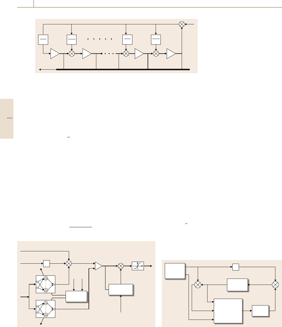
have negative real parts. The structure of the above
high-gain tracking error observer is shown in Fig. 11.8.
Substituting e with
ˆ
e in the controller u defined in
(11.24) with (11.38)gives
ˆ
u =
ˆ
u
a,v
+
ˆ
u
s,v
, (11.51)
where
ˆ
u
a,v
=
1
ˆ
g
v
(
ˆ
x)
−
ˆ
f
v
(
ˆ
x)+y
(n)
d
−k
ˆ
e
(11.52)
and
ˆ
u
s,v
=−
1
g
ˆ
k
s,v
sat
ˆ
σ
ν
,
(11.53)
with
ˆ
x = x
d
+
ˆ
e,
ˆ
k
s,v
= d
f
+d
g
|
ˆ
u
a,v
|+d
0
and
ˆ
σ =
b
P
m
ˆ
e.Let
ˆ
k
s
=d
f
+d
g
max
v
max|
ˆ
u
a,v
|
+d
0
,
Part B 11.5
212 Part B Automation Theory and Scientific Foundations
ê
(n–1)
α
n–1
ε
n–1
α
n
ε
n
ê
∫
ê
(n–2)
∫
+
+
ê
(1)
ê
(2)
α
1
ε
1
α
2
ε
2
∫
ê
e
∫
+
+
+
+
–
+
Fig. 11.8 Diagram of the high-gain
observer
and the inner maximization is taken over
ˆ
e ∈ Ω
ˆ
e
,
x
d
∈Ω
x
d
, y
(n)
d
∈Ω
y
d
, ω
f,v
∈Ω
f,v
,andω
g,v
∈Ω
g,v
.For
the high-gain observer described by (11.49), there exist
peaking phenomena [11.67]. Hence, the controller
ˆ
u de-
fined in (11.51) cannot be applied to the plant directly.
To eliminate the peaking phenomena, the saturation is
introduced into the control input
ˆ
u in (11.51). Let
Ω
ˆ
e
=
e :
1
2
e
P
m
e ≤c
ˆ
e
,
(11.54)
where c
ˆ
e
> c
e
.Let
S ≥max
v
max
u
e, x
d
, y
(n)
d
, ω
f,v
, ω
g,v
,
(11.55)
where u is defined in (11.24) and the inner maxi-
mization is taken over e ∈Ω
ˆ
e
, x
d
∈ Ω
x
d
, y
(n)
d
∈ Ω
y
d
,
ω
f,v
∈ Ω
f,v
,andω
g,v
∈ Ω
g,v
. Then the proposed di-
rect adaptive robust output feedback controller takes the
form
u
s
= S sat
ˆ
u
a,v
+
ˆ
u
s,v
S
.
(11.56)
ê
ê
x
ˆ
x
ˆ
ê
g
ˆ
υ
f
ˆ
υ
k
Adaptation
algorithms
Robustifying
component
y
d
(n)
u
ˆ
a,
υ
u
ˆ
s,
υ
u
s
÷
+
–
–
+
+
Fig. 11.9 Diagram of the direct adaptive robust output feedback
controller (DAROFC)
The adaptation laws for the weight vectors ω
f,v
and
ω
g,v
change correspondingly and take the following
new form, respectively
˙
ω
f,v
=Proj
ω
f,v
,η
f
ˆ
σξ
v
(
ˆ
x)
(11.57)
and
˙
ω
g,v
=Proj
ω
g,v
,η
g
ˆ
σξ
v
(
ˆ
x)
ˆ
u
a,v
.
(11.58)
A block diagram of the above direct adaptive robust
output feedback controller is shown in Fig.11.9, while
a block diagram of the closed-loop system is given
in Fig.11.10.
For the high-gain tracking error observer (11.49),
it is shown in [11.68] that there exists a con-
stant
∗
1
∈ (0, 1) such that, if ∈ (0,
∗
1
), then e(t)−
ˆ
e(t)≤β with β>0fort ∈[t
0
+T
1
( ), t
0
+T
3
), where
T
1
( ) is a finite time and t
0
+T
3
is the moment when
the tracking error e(t) leaves the compact set Ω
e
for
the first time. Moreover, we have lim
→0
+
T
1
( ) = 0
and c
e
1
=
1
2
e(t
0
+T
1
( ))
P
m
e(t
0
+T
1
( )) < c
e
.Forthe
plant (11.2) driven by the direct adaptive robust output
feedback controller given by (11.56) with the adapta-
tion laws (11.57)and(11.58), if one of the following
conditions is satisfied:
ê
x
ˆ
c
e
Self-organizing
RCRBF
Network-based
DAROFC
Plant
High-gain
observer
Reference
signal
generator
y
d
(n)
u
s
x
d
y
d
y
+
–
+
+
Fig. 11.10 Diagram of the closed-loop system driven by the
output feedback controller
Part B 11.5
Control of Uncertain Systems 11.6 Examples 213
•
The dwelling time T
d
of the self-organizing RBF
network is selected such that
T
d
≥
1
μ
ln
3
2
,
(11.59)
•
The constants c and ν satisfy the inequality
0 < c
f
+c
g
<
exp(μT
d
)−1
3−2exp(μT
d
)
ˆ
k
s
ν
4μ
+r
,
(11.60)
and if η
f
, η
g
,andν are selected such that
c
e
≥c
e
1
+c
f
+c
g
(11.61)
and
c
e
> 2
c
f
+c
g
+
ˆ
k
s
ν
8μ
+c
f
+c
g
, (11.62)
there exists a constant
∗
∈(0, 1) suchthat, if ∈(0,
∗
),
then e(t) ∈Ω
e
and x(t) ∈Ω
x
for t ≥t
0
. Moreover, there
exists a finite time T ≥t
0
+T
1
( ) such that
1
2
e(t)
P
m
e(t) ≤2
c
f
+c
g
+
ˆ
k
s
ν
8μ
+r +c
f
+c
g
(11.63)
with some r > 0fort ≥ T. In addition, suppose that
there exists a finite time T
s
≥t
0
+T
1
( ) such that v =v
s
for t ≥ T
s
. Then there exists a finite time T ≥ T
s
such
that
1
2
e
(t)P
m
e(t) ≤2
c
f
+c
g
+
ˆ
k
s
ν
8μ
+r
(11.64)
for t ≥ T. A proof of the above statement can be found
in [11.58]. It can be seen that the performance of the
output feedback controller approaches that of the state
feedback controller as approaches zero.
11.6 Examples
In this section, two example systems are used to il-
lustrate the features of the proposed direct adaptive
robust controllers. In Example 11.1, a benchmark prob-
lem from the literature is used to illustrate the controller
performance under different situations. Especially, the
reference signal changes during the operation in or-
der to demonstrate the advantage of the self-organizing
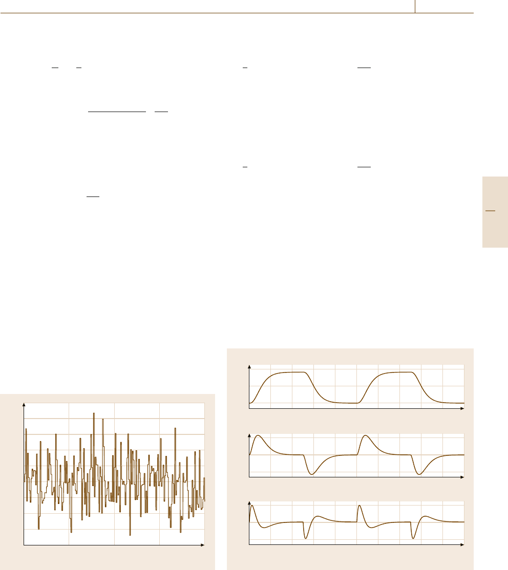
0 5 10 15 20
Time (s)
2.5
2
1.5
1
0.5
0
–0.5
–1
–1.5
–2
Fig. 11.11 Disturbance d in example 11.1
RBF network. In Example 11.2, the Duffing forced
oscillation system is employed to test the controller per-
formance for time-varying systems.
0
5
1
0.5
0
0.5 1 1.5 2 2.5
Reference signal
First time derivative
Second time derivative
3 3.5 4 4.5
0
5
2
0
–2
0.5 1 1.5 2 2.5 3 3.5 4 4.5
0
5
Time (s)
20
0
–20
0.5 1 1.5 2 2.5 3 3.5 4 4.5
Fig. 11.12 Reference signal and its time derivatives
Part B 11.6
214 Part B Automation Theory and Scientific Foundations
0
25
Time (s)
Number of hidden neurons
60
40
20
0
5101520
0 25
Control input
10
0
–10
–20
5101520
0 25
Tracking error
× 10
–3
a) DARSFC
5
0
–5
5101520
0
25
Time (s)
Number of hidden neurons
60
40
20
0
5101520
0 25
Control input
10
0
–10
–20
5101520
0 25
Tracking error
× 10
–3
b) DAROFC
5
0
–5
5101520
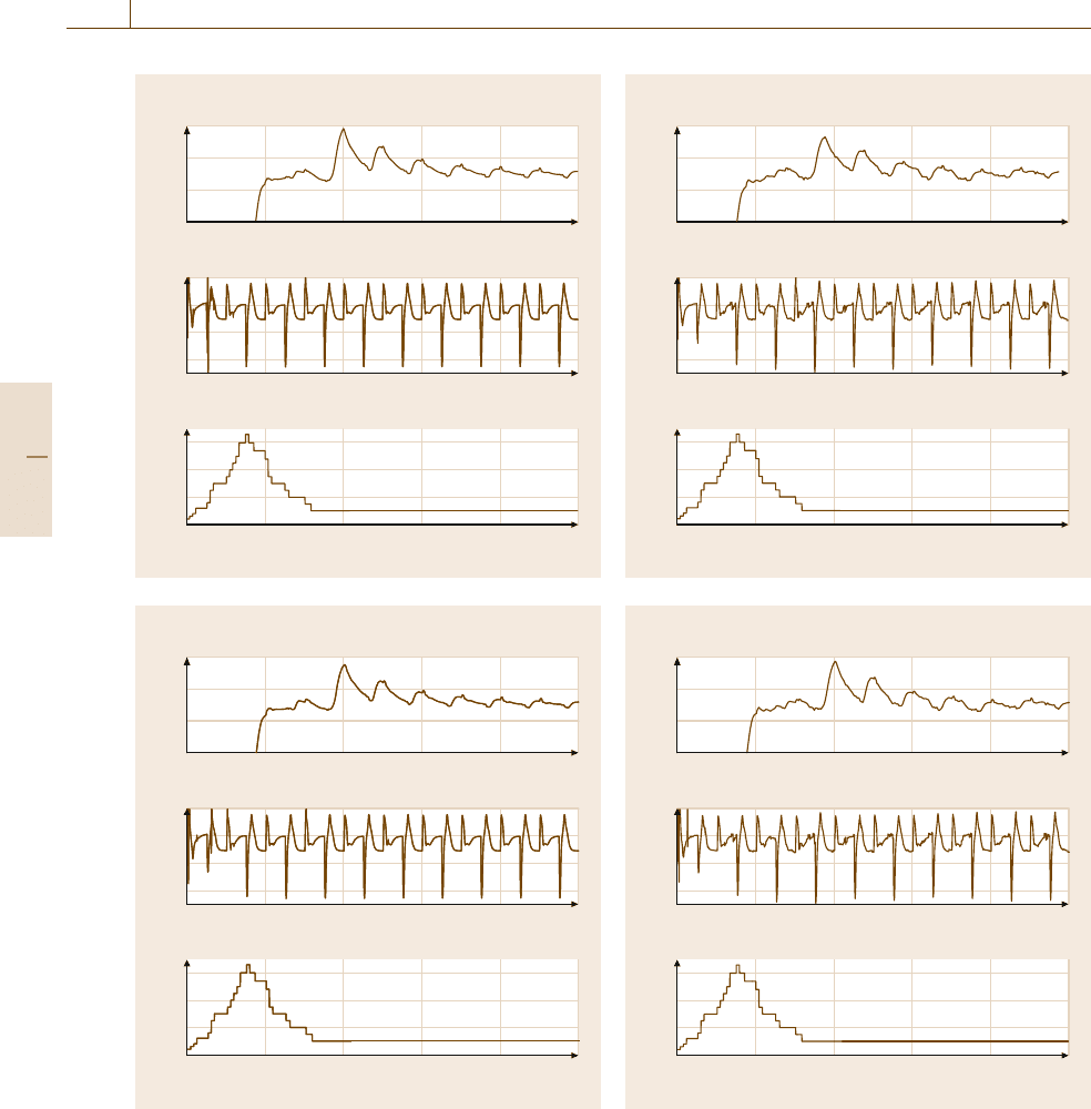
Fig. 11.13a,b Controller performance without disturbance
in example 11.1.
(a) State feedback controller, (b) output
feedback controller
0
25
Time (s)
Number of hidden neurons
60
40
20
0
5 101520
0 25
Control input
10
0
–10
–20
5 101520
0 25
Tracking error
× 10
–3
a) DARSFC
5
0
–5
5 101520
0
25
Time (s)
Number of hidden neurons
60
40
20
0
5 101520
0 25
Control input
10
0
–10
–20
5 101520
0 25
Tracking error
× 10
–3
b) DAROFC
5
0
–5
5 101520
Fig. 11.14a,b Controller performance with disturbance in
Example 11.1.
(a) State feedback controller, (b) output
feedback controller
Part B 11.6
