Moran M.J., Shapiro H.N. Fundamentals of Engineering Thermodynamics
Подождите немного. Документ загружается.

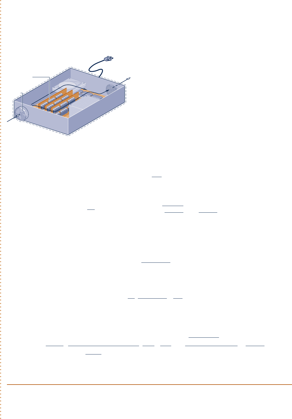
SOLUTION
Known:
The electronic components of a computer are cooled by air flowing through a fan mounted at the inlet
of the electronics enclosure. Conditions are specified for the air at the inlet and exit. The power required by the
electronics and the fan are also specified.
Find: Determine the smallest fan area for which the specified limits are met.
Schematic and Given Data:
Analysis: The inlet area A
1
can be determined from the mass flow rate m
#
and Eq. 4.4b, which can be rearranged
to read
A
1
5
m
#
y
1
V
1
(a)
The mass flow rate can be evaluated, in turn, from the steady-state energy rate balance, Eq. 4.20a.
0 5 Q
#
cv
2 W
#
cv
1 m
#
c
1h
1
2 h
2
21
a
V
2
1
2 V
2
2
2
b
1 g1z
1
2 z
2
2
d
The underlined terms drop out by assumptions 2 and 3, leaving
0 52W
#
cv
1 m
#
1h
1
2 h
2
2
where W
#
cv
accounts for the total electric power provided to the electronic components and the fan: W
#
cv
5
1
280 W
2
1
1
218 W
2
5298 W. Solving for m
#
, and using assumption 4 with Eq. 3.51 to evaluate (h
1
2 h
2
)
m
#
5
12W
#
cv
2
c
p
1T
2
2 T
1
2
Introducing this into the expression for A
1
, Eq. (a), and using the ideal gas model to evaluate the specific
volume y
1
A
1
5
1
V
1
c
12W
?
cv
2
c
p
1T
2
2 T
1
2
da
RT
1
p
1
b
From this expression we see that A
1
increases when V
1
and/or T
2
decrease. Accordingly, since V
1
# 1.3 m/s and
T
2
# 305 K (328C), the inlet area must satisfy
A
1
$
1
1.3 m
/
s
≥
98 W
a1.005
k
J
k
g
? K
b1305 2 2932K
`
1 kJ
10
3
J
``
1 J
/
s
1 W
`¥
±
a
8314 N ? m
28.97 kg ? K
b293 K
1.01325 3 10
5
N
/
m
2
≤
`
10
4
cm
2
1 m
2
`
$
5
2 cm
2
For the specified conditions, the smallest fan area is 52 cm
2
.
4.9 Heat Exchangers 193
+
–
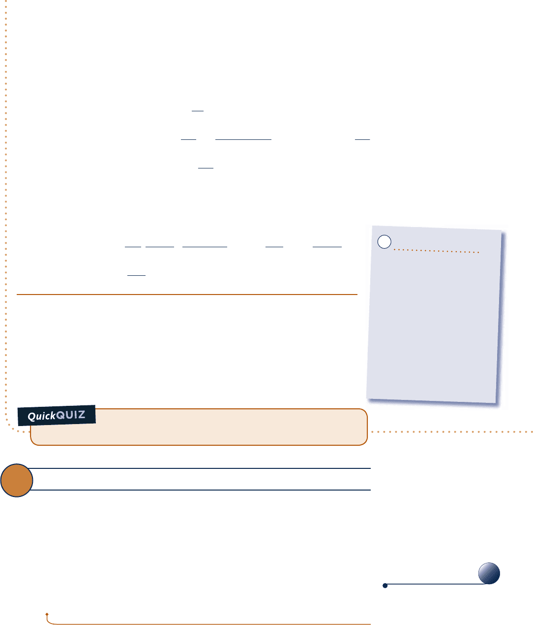
Air in
Air out
T
1
= 20°C
p
1
= 1 atm
V
1
≤ 1.3 m/s
1
2
T
2
≤ 32°C
Electronic
components
Fan
Fig. E4.8
Engineering Model:
1.
The control volume shown on the accompa-
nying figure is at steady state.
2. Heat transfer from the outer surface of the
electronics enclosure to the surroundings is
negligible. Thus,
Q
#
cv
5 0.
3. Changes in kinetic and potential energies can
be ignored.
4. Air is modeled as an ideal gas with
c
p
5 1.005 kJ/kg
?
K.
➋
➊
c04ControlVolumeAnalysisUsingEn193 Page 193 6/23/10 9:50:41 AM user-s146 c04ControlVolumeAnalysisUsingEn193 Page 193 6/23/10 9:50:41 AM user-s146 /Users/user-s146/Desktop/Merry_X-Mas/New/Users/user-s146/Desktop/Merry_X-Mas/New
194 Chapter 4 Control Volume Analysis Using Energy
If heat transfer occurs at a rate of 11 W from the outer surface
of the computer case to the surroundings, determine the smallest fan inlet
area for which the limits on entering air velocity and exit air temperature
are met if the total power input remains at 98 W. Ans. 46 cm
2
.
12
Partiall
y
o
p
en valve
Porous plug
12
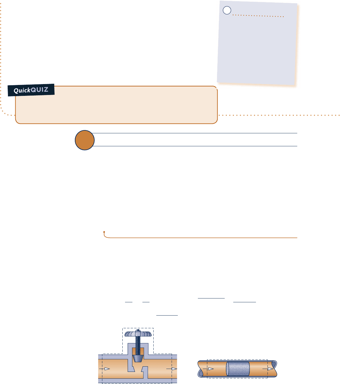
Fig. 4.15 Examples of throttling devices.
➊ Cooling air typically enters and exits electronic enclosures at low velocities,
and thus kinetic energy effects are insignificant.
➋ The applicability of the ideal gas model can be checked by reference to
the generalized compressibility chart. Since the temperature of the air
increases by no more than 128C, the specific heat c
p
is nearly constant
(Table A-20).
Ability to…
❑
apply the steady-state
energy rate balance to a
control volume.
❑
apply the mass flow rate
expression, Eq. 4.4b.
❑
develop an engineering model.
❑
retrieve property data of air
modeled as an ideal gas.
✓Skills Developed
4.10 Throttling Devices
A significant reduction in pressure can be achieved simply by introducing a restriction
into a line through which a gas or liquid flows. This is commonly done by means of a par-
tially opened valve or a porous plug. These throttling devices are illustrated in Fig. 4.15.
An application of throttling occurs in vapor-compression refrigeration systems,
where a valve is used to reduce the pressure of the refrigerant from the pressure at
the exit of the condenser to the lower pressure existing in the evaporator. We consider
this further in Chap. 10. Throttling also plays a role in the Joule–Thomson expansion
considered in Chap. 11. Another application involves the throttling calorimeter, which
is a device for determining the quality of a two-phase liquid–vapor mixture. The
throttling calorimeter is considered in Example 4.9.
throttling calorimeter
4.10.1
Throttling Device Modeling Considerations
For a control volume enclosing a throttling device, the only work is flow work at
locations where mass enters and exits the control volume, so the term W
#
cv
drops out
of the energy rate balance. There is usually no significant heat transfer with the sur-
roundings, and the change in potential energy from inlet to exit is negligible. Thus,
the underlined terms of Eq. 4.20a (repeated below) drop out, leaving the enthalpy
and kinetic energy terms, as shown by Eq. (a). That is,
0 5 Q
#
cv
2 W
#
cv
1 m
#
c
1h
1
2 h
2
21
1V
2
1
2 V
2
2
2
2
1 g1z
1
2 z
2
2
d
0 5 1h
1
2 h
2
21
V
2
1
2 V
2
2
2
(a)
c04ControlVolumeAnalysisUsingEn194 Page 194 6/23/10 9:50:44 AM user-s146 c04ControlVolumeAnalysisUsingEn194 Page 194 6/23/10 9:50:44 AM user-s146 /Users/user-s146/Desktop/Merry_X-Mas/New/Users/user-s146/Desktop/Merry_X-Mas/New
Although velocities may be relatively high in the vicinity of the restriction imposed
by the throttling device on the flow through it, measurements made upstream and
downstream of the reduced flow area show in most cases that the change in the
specific kinetic energy of the flowing substance between these locations can be
neglected. With this further simplification, Eq. (a) reduces to
h
2
5 h
1
1p
2
,
p
1
2
(4.22)
When the flow through the valve or other restriction is idealized in this way, the
process is called a throttling process.
throttling process
4.10.2
Using a Throttling Calorimeter to Determine Quality
The next example illustrates use of a throttling calorimeter to determine steam quality.
Measuring Steam Quality
c c c c EXAMPLE 4.9 c
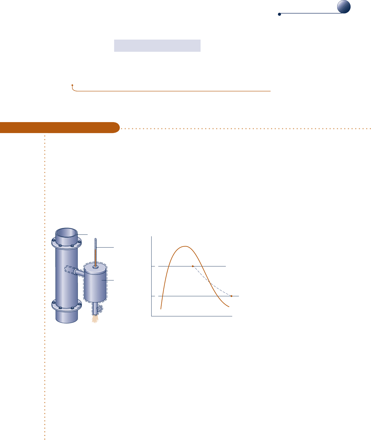
A supply line carries a two-phase liquid–vapor mixture of steam at 300 lbf/in.
2
A small fraction of the flow in
the line is diverted through a throttling calorimeter and exhausted to the atmosphere at 14.7 lbf/in.
2
The tem-
perature of the exhaust steam is measured as 2508F. Determine the quality of the steam in the supply line.
SOLUTION
Known:
Steam is diverted from a supply line through a throttling calorimeter and exhausted to the atmosphere.
Find: Determine the quality of the steam in the supply line.
Schematic and Given Data:
Calorimeter
Thermometer
Steam line, 300 lbf/in.
2
p
2
= 14.7 lbf/in.
2
T
2
= 250°F
1
2
p
1
= 300 lbf/in.
2
p
2
= 14.7 lbf/in.
2
T
2
= 250°F
2
1
v
p
Fig. E4.9
Engineering Model:
1.
The control volume shown on the accompanying figure is at steady state.
2. The diverted steam undergoes a throttling process.
Analysis: For a throttling process, the energy and mass balances reduce to give h
2
5 h
1
, which agrees with Eq.
4.22. Thus, with state 2 fixed, the specific enthalpy in the supply line is known, and state 1 is fixed by the
known values of p
1
and h
1
.
➊ As shown on the accompanying p–y diagram, state 1 is in the two-phase liquid–vapor region and state 2 is
in the superheated vapor region. Thus,
h
2
5 h
1
5 h
f1
1 x
1
1
h
g
1
2 h
f1
2
4.10 Throttling Devices 195
A
A
Throttling_Dev
A.23 – Tabs a, b, & c
c04ControlVolumeAnalysisUsingEn195 Page 195 6/23/10 1:34:56 PM user-s146 c04ControlVolumeAnalysisUsingEn195 Page 195 6/23/10 1:34:56 PM user-s146 /Users/user-s146/Desktop/Merry_X-Mas/New/Users/user-s146/Desktop/Merry_X-Mas/New
196 Chapter 4 Control Volume Analysis Using Energy
Solving for x
1
,
x
1
5
h
2
2 h
f1
h
g
1
2 h
f1
From Table A-3E at 300 lbf/in.
2
, h
f1
5 394.1 Btu/lb and h
g1
5 1203.9 Btu/lb. At
14.7 lbf/in.
2
and 2508F, h
2
5 1168.8 Btu/lb from Table A-4E. Inserting values into
the above expression, the quality of the steam in the line is x
1
5 0.957 (95.7%).
➊ For throttling calorimeters exhausting to the atmosphere, the quality of the
steam in the line must be greater than about 94% to ensure that the steam
leaving the calorimeter is superheated.
If the supply line carried saturated vapor at 300 lbf/in.
2
, deter-
mine the temperature at the calorimeter exit, in 8F, for the same exit pres-
sure, 14.7 lbf/in.
2
Ans. 3248F.
Ability to…
❑
apply Eq. 4.22 for a throt-
tling process.
❑
retrieve property data for
water
✓
Skills Developed
BIOCONNECTIONS Living things also can be considered integrated sys-
tems. Figure 4.17 shows a control volume enclosing a tree receiving solar radiation.
As indicated on the figure, a portion of the incident radiation is reflected to the
surroundings. Of the net solar energy received by the tree, about 21% is returned to the
surroundings by heat transfer, principally convection. Water management accounts for most
of the remaining solar input.
Trees sweat as do people; this is called evapotranspiration. As shown in Fig. 4.17, about
78% of the net solar energy received by the tree is used to pump liquid water from the
surroundings, primarily the ground, convert it to a vapor, and discharge it to the surround-
ings through tiny pores (called stomata) in the leaves. Nearly all the water taken up is lost
in this manner and only a small fraction is used within the tree. Applying an energy balance
to the control volume enclosing the tree, just 1% of the net solar energy received by the
tree is left for use in the production of biomass (wood and leaves). Evapotranspiration
benefits trees but also contributes significantly to water loss from watersheds, illustrating
that in nature as in engineering there are trade-offs.
4.11 System Integration
Thus far, we have studied several types of components selected from
those commonly seen in practice. These components are usually encoun-
tered in combination, rather than individually. Engineers often must
creatively combine components to achieve some overall objective, sub-
ject to constraints such as minimum total cost. This important engineer-
ing activity is called system integration.
In engineering practice and everyday life, integrated systems are
regularly encountered. Many readers are already familiar with a par-
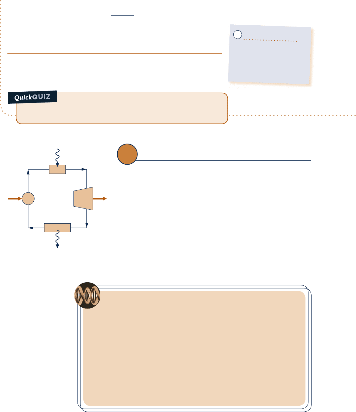
ticularly successful system integration: the simple power plant shown
in Fig. 4.16. This system consists of four components in series: a turbine-
generator, condenser, pump, and boiler. We consider such power plants
in detail in subsequent sections of the book.
Boiler
Condenser
TurbinePump
Q
in
˙
Q
out
˙
W
p
˙
W
t
˙
Fig. 4.16 Simple vapor power plant.
c04ControlVolumeAnalysisUsingEn196 Page 196 6/23/10 9:50:45 AM user-s146 c04ControlVolumeAnalysisUsingEn196 Page 196 6/23/10 9:50:45 AM user-s146 /Users/user-s146/Desktop/Merry_X-Mas/New/Users/user-s146/Desktop/Merry_X-Mas/New
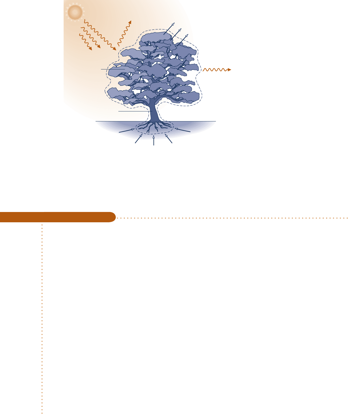
Example 4.10 provides another illustration of an integrated system. This case
involves a waste heat recovery system.
Evapotranspiration
(78%)
Biomass
production
(1%)
Moisture
Reflected
Incident
Heat transfer
(21%)
Vapor
Solar
radiation
Fig. 4.17 Control volume enclosing a tree.
Evaluating Performance of a Waste Heat Recovery System
c c c c EXAMPLE 4.10 c
An industrial process discharges 2 3 10
5
ft
3
/min of gaseous combustion products at 4008F, 1 atm. As shown in
Fig. E4.10, a proposed system for utilizing the combustion products combines a heat-recovery steam generator
with a turbine. At steady state, combustion products exit the steam generator at 2608F 1 atm and a separate
stream of water enters at 40 lbf/in.
2
, 1028F with a mass flow rate of 275 lb/min. At the exit of the turbine, the
pressure is 1 lbf/in.
2
and the quality is 93%. Heat transfer from the outer surfaces of the steam generator and
turbine can be ignored, as can the changes in kinetic and potential energies of the flowing streams. There is no
significant pressure drop for the water flowing through the steam generator. The combustion products can be
modeled as air as an ideal gas.
(a) Determine the power developed by the turbine, in Btu/min.
(b) Determine the turbine inlet temperature, in 8F.
(c) Evaluating the power developed at $0.08 per kW
?
h, determine the value of the power, in $/year, for 8000 hours
of operation annually.
SOLUTION
Known:
Steady-state operating data are provided for a system consisting of a heat-recovery steam generator and
a turbine.
Find: Determine the power developed by the turbine and the turbine inlet temperature. Evaluate the annual
value of the power developed.
4.11 System Integration 197
c04ControlVolumeAnalysisUsingEn197 Page 197 6/23/10 9:50:46 AM user-s146 c04ControlVolumeAnalysisUsingEn197 Page 197 6/23/10 9:50:46 AM user-s146 /Users/user-s146/Desktop/Merry_X-Mas/New/Users/user-s146/Desktop/Merry_X-Mas/New
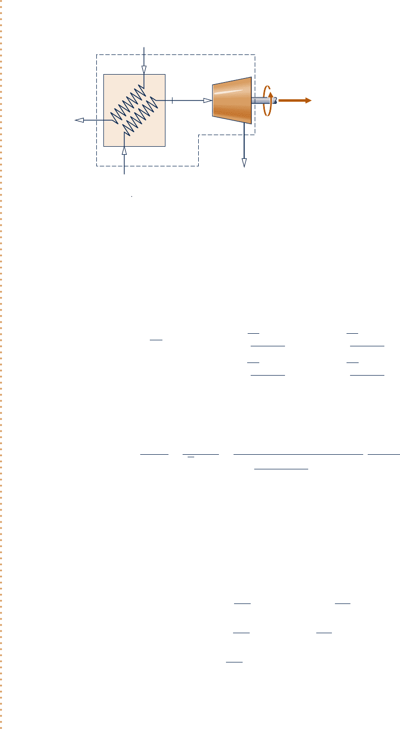
198 Chapter 4
Control Volume Analysis Using Energy
4
5
1
2
3
Combustion products in
p
1
= 1 atm
T
1
= 400°F
(AV)
1
= 2 × 10
5
ft
3
/min
Combustion products out
T
2
= 260°F
p
2
= 1atm
Turbine
Power
out
Steam
generator
water in
p
3
= 40 lbf/in.
2
T
3
= 102°F
m
3
= 275 lb/min
water out
p
5
= 1 lbf/in.
2
x
5
= 93%
Fig. E4.10
Analysis:
(a)
The power developed by the turbine is determined from a control volume enclosing both the steam genera-
tor and the turbine. Since the gas and water streams do not mix, mass rate balances for each of the streams
reduce, respectively, to give
m
#
1
5 m
#
2
,
m
#
3
5 m
#
5
For this control volume, the appropriate form of the steady-state energy rate balance is Eq. 4.18, which reads
0 5 Q
#
cv
2 W
#
cv
1 m
#
1
ah
1
1
V
2
1
2
1 gz
1
b1 m
#
3
ah
3
1
V
2
3
2
1 gz
3
b
2 m
#
2
ah
2
1
V
2
2
2
1 gz
2
b2 m
#
5
ah
5
1
V
2
5
2
1 gz
5
b
The underlined terms drop out by assumption 2. With these simplifications, together with the above mass flow
rate relations, the energy rate balance becomes
W
#
cv
5 m
#
1
1h
1
2 h
2
21 m
#
3
1h
3
2 h
5
2
The mass flow rate m
#
1
can be evaluated with given data at inlet 1 and the ideal gas equation of state
m
#
1
5
1AV2
1
y
1
5
1AV2
1
p
1
1R
/
M2T
1
5
12 3 10
5
ft
3
/
min2114.7 lbf
/
in.
2
2
a
1545 ft ? lbf
28.97 lb ? 8R
b
18608R2
`
144 in.
2
1 ft
2
`
5 9230.6 lb
/
min
The specific enthalpies h
1
and h
2
can be found from Table A-22E: At 8608R, h
1
5 206.46 Btu/lb, and at 7208R h
2
5
172.39 Btu/lb. At state 3, water is a liquid. Using Eq. 3.14 and saturated liquid data from Table A-2E,
h
3
<
h
f
1
T
3
2
5 70 Btu
/
lb. State 5 is a two-phase liquid–vapor mixture. With data from Table A-3E and the given quality
h
5
5 h
f5
1 x
5
1
h
g
5
2 h
f5
2
5 69.74 1 0.93
1
1036.0
2
5 1033.2 Btu
/
lb
Substituting values into the expression for W
#
cv
W
#
cv
5
a
9230.6
lb
min
b
1206.46 2 172.392
Btu
lb
1
a
275
lb
min
b
170 2 1033.22
Btu
lb
5 49610
B
tu
min
Engineering Model:
1.
The control volume shown on the
accompanying figure is at steady state.
2. Heat transfer is negligible, and
changes in kinetic and potential
energy can be ignored.
3. There is no pressure drop for water
flowing through the steam generator.
4. The combustion products are modeled
as air as an ideal gas.
Schematic and Given Data:
c04ControlVolumeAnalysisUsingEn198 Page 198 6/23/10 9:50:46 AM user-s146 c04ControlVolumeAnalysisUsingEn198 Page 198 6/23/10 9:50:46 AM user-s146 /Users/user-s146/Desktop/Merry_X-Mas/New/Users/user-s146/Desktop/Merry_X-Mas/New
4.12 Transient Analysis 199
Taking a control volume enclosing just the turbine, evaluate
the turbine inlet temperature, in °F. Ans. 354°F.
(b) To determine T
4
, it is necessary to fix the state at 4. This requires two independent property values. With
assumption 3, one of these properties is pressure, p
4
5 40 lbf/in.
2
The other is the specific enthalpy h
4
, which can
be found from an energy rate balance for a control volume enclosing just the steam generator. Mass rate bal-
ances for each of the two streams give m
#
1
5 m
#
2
and m
#
3
5 m
#
4
. With assumption 2 and these mass flow rate rela-
tions, the steady-state form of the energy rate balance reduces to
0 5 m
#
1
1
h
1
2 h
2
2
1 m
#
3
1
h
3
2 h
4
2
Solving for h
4
h
4
5 h
3
1
m
#
1
m
#
3
1h
1
2 h
2
2
5 70
Btu
l
b
1
a
9230.6 lb
/
min
2
75
l
b
/
min
b
1206.46 2 172.392
Btu
l
b
5 1213.6
B
tu
l
b
Interpolating in Table A-4E at p
4
5 40 lbf/in.
2
with h
4
, we get T
4
5 3548F.
(c) Using the result of part (a), together with the given economic data and appropriate conversion factors, the
value of the power developed for 8000 hours of operation annually is
annual value 5 a49610
Btu
min
`
60 min
1 h
``
1 kW
3413 Btu
/
h
`ba8000
h
year
ba0.08
$
kW ? h
b
5 558,000
$
y
ear
➊
Alternatively, to determine h
4
a control volume enclosing just the turbine
can be considered.
➋ The decision about implementing this solution to the problem of utilizing
the hot combustion products discharged from an industrial process would
necessarily rest on the outcome of a detailed economic evaluation, including
the cost of purchasing and operating the steam generator, turbine, and aux-
iliary equipment.
Ability to…
❑
apply the steady-state
mass and energy rate bal-
ances to a control volume.
❑
apply the mass flow rate
expression, Eq. 4.4b.
❑
develop an engineering model.
❑
retrieve property data for
water and for air modeled
as an ideal gas.
❑
conduct an elementary
economic evaluation.
✓
Skills Developed
➊
➋
4.12 Transient Analysis
Many devices undergo periods of transient operation during which the state changes
with time. Examples include the startup or shutdown of turbines, compressors, and
motors. Additional examples include vessels being filled or emptied, as considered
in Example 4.2 and in the discussion of Fig. 1.5. Because property values, work and
heat transfer rates, and mass flow rates may vary with time during transient opera-
tion, the steady-state assumption is not appropriate when analyzing such cases. Spe-
cial care must be exercised when applying the mass and energy rate balances, as
discussed next.
4.12.1
The Mass Balance in Transient Analysis
First, we place the control volume mass balance in a form that is suitable for transient
analysis. We begin by integrating the mass rate balance, Eq. 4.2, from time 0 to a final
transient
A
A
System_Types
A.1 – Tab d
c04ControlVolumeAnalysisUsingEn199 Page 199 6/23/10 1:35:06 PM user-s146 c04ControlVolumeAnalysisUsingEn199 Page 199 6/23/10 1:35:06 PM user-s146 /Users/user-s146/Desktop/Merry_X-Mas/New/Users/user-s146/Desktop/Merry_X-Mas/New

200 Chapter 4 Control Volume Analysis Using Energy
time t. That is
#
t
0
a
dm
cv
dt
bdt 5
#
t
0
a
a
i
m
#
i
bdt 2
#
t
0
a
a
e
m
#
e
bd
t
This takes the form
m
cv
1t22 m
cv
1025
a
i
a
#
t
0
m
#
i
dtb2
a
e
a
#
t
0
m
#
e
dtb
Introducing the following symbols for the underlined terms
m
i
5
#
t
0
m
#
i
dt μ
amount of mass
entering the control
volume through inlet i,
from time 0 to t
m
e
5
#
t
0
m
#
e
dt μ
amount of mass
exiting the control
volume through exit e,
from time 0 to t
the mass balance becomes
m
cv
1t22 m
cv
1025
a
i
m
i
2
a
e
m
e
(4.23)
In words, Eq. 4.23 states that the change in the amount of mass contained in the control
volume equals the difference between the total incoming and outgoing amounts of mass.
4.12.2
The Energy Balance in Transient Analysis
Next, we integrate the energy rate balance, Eq. 4.15, ignoring the effects of kinetic
and potential energy. The result is
U
cv
1t22 U
cv
1025 Q
cv
2 W
cv
1
a
i
a
#
t
0
m
#
i
h
i
dtb2
a
e
a
#
t
0
m
#
e
h
e
dtb
(4.24)
where Q
cv
accounts for the net amount of energy transferred by heat into the control
volume and W
cv
accounts for the net amount of energy transferred by work, except
for flow work. The integrals shown underlined in Eq. 4.24 account for the energy
carried in at the inlets and out at the exits.
For the special case where the states at the inlets and exits are constant with time,
the respective specific enthalpies, h
i
and h
e
, are constant, and the underlined terms of
Eq. 4.24 become
#
t
0
m
#
i
h
i
dt 5 h
i
#
t
0
m
#
i
dt 5 h
i
m
i
#
t
0
m
#
e
h
e
dt 5 h
e
#
t
0
m
#
e
dt 5 h
e
m
e
Equation 4.24 then takes the following special form
U
cv
1t22 U
cv
1025 Q
cv
2 W
cv
1
a
i
m
i
h
i
2
a
e
m
e
h
e
(4.25)
where m
i
and m
e
account, respectively, for the amount of mass entering the control volume
through inlet i and exiting the control volume through exit e, each from time 0 to t.
Whether in the general form, Eq. 4.24, or the special form, Eq. 4.25, these equations
account for the change in the amount of energy contained within the control volume
as the difference between the total incoming and outgoing amounts of energy.
Another special case is when the intensive properties within the control volume
are uniform with position at a particular time t. Accordingly, the specific volume and
c04ControlVolumeAnalysisUsingEn200 Page 200 6/23/10 9:50:51 AM user-s146 c04ControlVolumeAnalysisUsingEn200 Page 200 6/23/10 9:50:51 AM user-s146 /Users/user-s146/Desktop/Merry_X-Mas/New/Users/user-s146/Desktop/Merry_X-Mas/New
the specific internal energy are uniform throughout and can depend only on time—
that is, y(t) and u(t), respectively. Then
m
cv
1
t
2
5 V
cv
1
t
2
y
y
1
t
2
(4.26)
U
cv
1
t
2
5 m
cv
1
t
2
u
1
t
2
(4.27)
If the control volume is comprised of different phases at time t, the state of each
phase is assumed uniform throughout.
Equations 4.23 and 4.25–4.27 are applicable to a wide range of transient cases
where inlet and exit states are constant with time and intensive properties within the
control volume are uniform with position initially and finally.
in cases involving the filling of containers having a single inlet
and no exit, Eqs. 4.23, 4.25, and 4.27 combine to give
m
cv
1t2u1t22 m
cv
102u1025 Q
cv
2 W
cv
1 h
i
1m
cv
1t22 m
cv
1022 (4.28)
The details are left as an exercise. See Examples 4.12 and 4.13 for this type of transient
application. b b b b b
4.12.3
Transient Analysis Applications
The following examples provide illustrations of the transient analysis of control vol-
umes using the conservation of mass and energy principles. In each case considered,
to emphasize fundamentals we begin with general forms of the mass and energy bal-
ances and reduce them to forms suited for the case at hand, invoking the idealizations
discussed in this section as warranted.
The first example considers a vessel that is partially emptied as mass exits through
a valve.
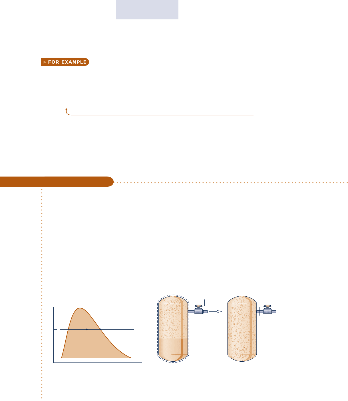
e
Pressure
regulating valve
Saturated water-
vapor removed,
while the tank
is heated
e
Initial: two-phase
liquid-vapor mixture
Final: saturated vapor
T
v
260°C
2, e1
Fig. E4.11
4.12 Transient Analysis 201
Evaluating Heat Transfer for a Partially-Emptying Tank
c c c c EXAMPLE 4.11 c
A tank having a volume of 0.85 m
3
initially contains water as a two-phase liquid–vapor mixture at 2608C and a
quality of 0.7. Saturated water vapor at 2608C is slowly withdrawn through a pressure-regulating valve at the top
of the tank as energy is transferred by heat to maintain the pressure constant in the tank. This continues until
the tank is filled with saturated vapor at 2608C. Determine the amount of heat transfer, in kJ. Neglect all kinetic
and potential energy effects.
SOLUTION
Known:
A tank initially holding a two-phase liquid–vapor mixture is heated while saturated water vapor is slowly
removed. This continues at constant pressure until the tank is filled only with saturated vapor.
Find: Determine the amount of heat transfer.
Schematic and Given Data:
c04ControlVolumeAnalysisUsingEn201 Page 201 6/23/10 9:50:53 AM user-s146 c04ControlVolumeAnalysisUsingEn201 Page 201 6/23/10 9:50:53 AM user-s146 /Users/user-s146/Desktop/Merry_X-Mas/New/Users/user-s146/Desktop/Merry_X-Mas/New

202 Chapter 4 Control Volume Analysis Using Energy
Engineering Model:
1.
The control volume is defined by the dashed line on the accompanying diagram.
2. For the control volume, W
#
cv
5 0 and kinetic and potential energy effects can be neglected.
3. At the exit the state remains constant.
4. The initial and final states of the mass within the vessel are equilibrium states.
Analysis: Since there is a single exit and no inlet, the mass rate balance Eq. 4.2 takes the form
dm
cv
dt
52m
#
e
With assumption 2, the energy rate balance Eq. 4.15 reduces to
dU
cv
dt
5 Q
#
cv
2 m
#
e
h
e
Combining the mass and energy rate balances results in
dU
cv
dt
5 Q
#
cv
1 h
e
dm
cv
dt
By assumption 3, the specific enthalpy at the exit is constant. Accordingly, integration of the last equation
gives
¢U
cv
5
Q
cv
1 h
e
¢m
cv
Solving for the heat transfer Q
cv
,
Q
cv
5 ¢U
cv
2 h
e
¢m
cv
or
Q
cv
5 1m
2
u
2
2 m
1
u
1
22 h
e
1m
2
2 m
1
2
where m
1
and m
2
denote, respectively, the initial and final amounts of mass within the tank.
The terms u
1
and m
1
of the foregoing equation can be evaluated with property values from Table A-2 at 2608C
and the given value for quality. Thus
u
1
5 u
f
1 x
1
1u
g
2 u
f
2
5 1128.4 1 10.7212599.0 2 1128.425 2157.8 kJ
/
kg
Also,
y
1
5 y
f
1 x
1
1y
g
2 y
f
2
5 1.2755 3 10
23
1 10.7210.04221 2 1.2755 3 10
23
25 29.93 3 10
23
m
3
/
kg
Using the specific volume y
1
, the mass initially contained in the tank is
m
1
5
V
y
1
5
0.85 m
3
129.93 3 10
23
m
3
/
kg2
5 28.4 kg
The final state of the mass in the tank is saturated vapor at 2608C so Table A-2 gives
u
2
5 u
g
12608C25 2599.0 kJ
/
kg,
y
2
5 y
g
12608C25 42.21 3 10
23
m
3
/
kg
The mass contained within the tank at the end of the process is
m
2
5
V
y
2
5
0.85 m
3
142.21 3 10
23
m
3
/
kg2
5 20.14 kg
Table A-2 also gives h
e
5 h
g
(2608C) 5 2796.6 kJ/kg.
➊
➋
c04ControlVolumeAnalysisUsingEn202 Page 202 6/23/10 9:50:54 AM user-s146 c04ControlVolumeAnalysisUsingEn202 Page 202 6/23/10 9:50:54 AM user-s146 /Users/user-s146/Desktop/Merry_X-Mas/New/Users/user-s146/Desktop/Merry_X-Mas/New
