Moeller. Wiring manual. Automation and Power distribution
Подождите немного. Документ загружается.


Moeller Wiring Manual 02/05
9-51
Specifications, Formulae, Tables
9
Electrically critical equipment of machines
Extract from IEC/EN 60204-1: (VDE 0113 part 1)
This world wide binding standard is used for the
electrical equipment of machines, provided that
for the type of machine to be equipped there is no
product standard (Type C).
Safety requirements regarding the protection of
personnel, machines and material according to
the European Machinery Directive are stressed
under the heading “Safety of machines”. The
degree of possible danger is to estimated by risk
assessment (EN 1050). The Standard also includes
requirements for equipment, engineering and
construction, as well as tests to ensure faultless
function and the effectiveness of protective
measures.
The following paragraphs are an extract from the
Standard.
Mains isolating device (main switches)
Every machine must be equipped with a
manually-operated main switch, henceforth
referred to as a mains isolating device. It must be
possible to isolate the entire electrical equipment
of the machine from the mains using the mains
isolating device. The breaking capacity
must be sufficient to simultaneously disconnect
the stalled current of the largest motor in the
machine and the total current drawn by all the
other loads in normal operation.
Its Off position must be lockable and must not be
indicated until the specified clearances and
creepage distances between all contacts have
been achieved. It must have only one On and one
Off position with associated stops. Star-delta,
reversing and multi-speed switches are not
permissible for use as mains isolating devices.
The tripped position of circuit-breakers is not
regarded as a switch position, therefore there is
no restriction on their use as mains isolating
devices.
Where there are several incomers, each one must
have a mains isolating device. Mutual interlocking
must be provided where a hazard may result from
only one mains isolating device being switched
off. Only circuit-breakers may be used as
remotely-operated switches. They must be
provided with an additional handle and be
lockable in the Off position.
Protection against electric shock
The following measures must be taken to protect
personnel against electric shock:
Protection against direct contact
This is understood as meaning protection by
means of an enclosure which can only be opened
by qualified personnel using a key or special tool.
Such personnel is not obliged to disable the mains
isolating device before opening the enclosure, Live
parts must be protected against direct contact in
accordance with IEC 50274 or VDE 0660 part 514.
Where the mains isolating device is interlocked
with the door, the restrictions mentioned in the
previous paragraph cease to apply because the
door can only be opened when the mains isolating
device is switched off. It is permissible for an
interlock to be removable by an electrician using a
tool, e.g. in order to search for a fault. Where an
interlock has been removed, it must still be
possible to switch off the mains isolating device.
Where it is possible for an enclosure to be opened
without using a key and without disconnection of
the mains isolating device, all live parts must at
the very least comply with IP 2X or IP XXB degree
of protection in accordance with IEC/EN 60529.
Protection against indirect contact
This involves prevention of a dangerous touch
voltage resulting from faulty insulation. To meet
this requirement, protective measures in
accordance with IEC 60364 or VDE 0100 must be
used. An additional measure is the use of
protective insulation (protection class II) to
IEC/EN 60439-1 or VDE 0660 Part 500.

Specifications, Formulae, Tables
Electrically critical equipment of machines
Moeller Wiring Manual 02/05
9-52
9
Protection of equipment
Protection in the event of power failure
When the power returns following a failure in the
supply, machines or parts of machines must not
start automatically where this would result in a
dangerous situation or damage to property. With
contactor controls this requirement can easily be
met via self-maintaining circuits.
For circuits with two-wire control, an additional
contactor relay with three-wire control in the
supply to the control circuit can carry out this
function. Mains isolating devices and
motor-protective circuit-breakers with
undervoltage releases also reliably prevent
automatic restarting on return of voltage.
Overcurrent protection
No overcurrent protective device is normally
required for the mains supply cable. Overcurrent
protection is provided by the protective device at
the head of the incoming supply. All other circuits
must be protected by means of fuses or
circuit-breakers.
The stipulation for fuses is that replacement must
be freely obtainable in the country in which the
fuses are used. This difficulty can be avoided by
using circuit-breakers, with the added benefits of
disconnection in all poles, rapid operational
readiness and prevention of single-phasing.
Overload protection of motors
Continously operating motors above 0.5 kW must
be protected against overload. Overload
protection is recommended for all other motors.
Motors which are frequently starting and braking
are difficult to protect and often require a special
protective device. Built-in thermal sensors are
particularly suitable for motors with restricted
cooling. In addition, the fitting of overload relays
is always recommended, particularly as protection
by stalled rotor.

Specifications, Formulae, Tables
Electrically critical equipment of machines
Moeller Wiring Manual 02/05
9-53
9
Control functions in the event of a fault
A fault in the electrical equipment must not result
in a dangerous situation or in damage. Suitable
measures must be taken to prevent danger from
arising. The expense of using appropriate
measures can be extremely high if applied
generally. To permit a better assessment of the
magnitude of the risk in conjunction with the
respective application, the Standard EN 954-1 has
been published:
„Safety-related parts of control systems Part 1:
General rules for design“.
The use of risk assessment to EN 954-1 is dealt
with in the Moeller manual “Safety Specifications
for Machines and Plant” (Order No. TB 0-009).
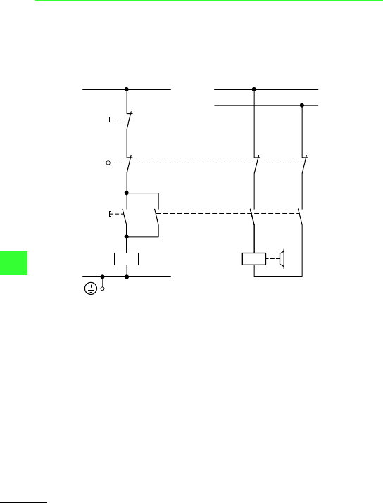
Emergency-Stop device
Every machine which could potentially cause
danger must be equipped with an
Emergency-Stop device which, in a main circuit
may be an Emergency-Stop switch, and in a
control circuit an Emergency-Stop control circuit
device.
Actuation of the Emergency-Stop device must
result in all current loads which could directly
result in danger, being disconnected by
de-energization via another device or circuit, i.e.
electromechanical devices such as contactors,
contactor relays or the undervoltage release of the
mains isolating device.
For direct manual operation, Emergency-Stop
control circuit devices must have a
mushroom-head push-button and positively
opening contacts. Once the Emergency-Stop
control circuit device has been actuated, it must
only be possible to restart the machine after local
resetting. Resetting alone must not allow
restarting.
Furthermore, the following apply for both
Emergency-Stop switch and Emergency control
circuit device:
• The handle must be red with a yellow
background
• Emergency-Stop devices must be quickly and
easily accessible in the event of danger
• The Emergency-Stop function must take
precedence over all other functions and
operations
• It must be possible to determine functional
capability by means of tests, especially in severe
environmental conditions
• Where there is separation into several
Emergency-Stop areas, it must be clearly
discernible to which area an Emergency-Stop
device applies
Emergency operations
The term Emergency-Stop is short and concise,
and should continue to be used for general usage.
It is not clear however from the term
Emergency-Stop which functions are carried out
with this. In order to be able to give a more precise
definition here, IEC/EN 60204-1 describes under
the generic term “Emergency operations” two
specific functions:
1. Emergency-Stop
This involves the possibility of stopping dangerous
motions as quickly as possible.
2. Emergency-Off
Where there is a risk of an electric shock by direct
contact, e.g. with live parts in electrical operating
areas, then an Emergency-Off device shall be
provided.

Specifications, Formulae, Tables
Electrically critical equipment of machines
Moeller Wiring Manual 02/05
9-54
9
Colours of push-buttons and their meanings
To IEC/EN 60073, VDE 0199, IEC/EN 60204-1
(VDE 0113 Part 1)
Colour
Meaning Typical application
RED
Emergency
• Emergency-Stop
•Fire fighting
YELLOW Abnormal condition Intervention, to suppress abnormal
conditions or to avoid unwanted
changes
GREEN
Safe condition Start from safe conditon
BLUE
Enforced action Resetting function
WHITE
No specific meaning assigned
• Start/ON (preferred)
•Stop/OFF
GREY
• Start/ON
•Stop/OFF
BLACK
• Start/ON
• Stop/Off (preferred)

Specifications, Formulae, Tables
Electrically critical equipment of machines
Moeller Wiring Manual 02/05
9-55
9
Colours of indicator lights and their meanings
To IEC/EN 60073, VDE 0199, IEC/EN 60204-1
(VDE 0113 Part 1)
Colours of illuminated push-buttons and their meanings
Both tables are valid for illuminated push-buttons,
Table 1 relating to the function of the actuators.
Colour
Meaning Explanation Typical application
RED
Emergency Warning of potential danger or
a situation which requires
immediate action
• Failure of pressure in the
lubricating system
• Temperature outside
specified (safe) limits
• Essential equipment
stopped by action of a
protective device
YELLOW Abnormal
condition
Impending critical condition
• Temperature (or pressure)
different from normal level
• Overload, which is
permissible for a limited
time
• Resetting
GREEN Safe
condition
Indication of safe operating
conditions or authorization to
proceed, clear way
• Cooling liquid circulating
• Automatic tank control
switched on
• Machine ready to be started
BLUE Enforced
action
Operator action essential
• Remove obstacle
• Switch over to Advance
WHITE No specific
meaning
assigned
(neutral)
Every meaning: may be used
whenever doubt exists about
the applicability of the colours
RED, YELLOW or GREEN; or as
confirmation
• Motor running
• Indication of operating
modes
Moeller Wiring Manual 02/05
9-56
Specifications, Formulae, Tables
9
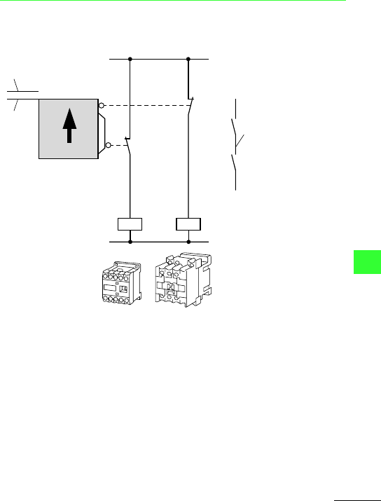
Measures for risk reduction
Risk reduction in the case of a fault
A fault in the electrical equipment must not result
in a dangerous situation or in damage. Suitable
measures must be taken to prevent danger from
arising.
The IEC/EN 60204 -1 specifies a range of
measures which can be taken to reduce danger in
the event of a fault.
Use of proven circuit engineering and components
a All switching functions on the non-earthed
side
b Use of break devices with positively opening
contacts (not to be confused with interlocked
opposing contacts)
c Shut-down by de-excitation (fail-safe in the
event of wire breakage)
d Circuit engineering measures which make
undesirable operational states in the event of
a fault unlikely (in this instance, simultaneous
interruption via contactor and position switch)
e Switching of all live conductors to the device
to be controlled
f Chassis earth connection of the control circuit
for operational purposes (not used as a
protective measure)
Redundancy
This means the existence of an additional device
or system which takes over the function in the
event of a fault.
L01
0
K1
K1
I
⎧
⎪
⎪
⎪
⎪
⎨
⎪
⎪
⎪
⎪
⎩
⎧
⎪
⎨
⎪
⎩
L1
L2
L02
햲
햳
햴
햵
햶
햷
Moeller Wiring Manual 02/05
9-57
Specifications, Formulae, Tables
9
Measures for risk avoidance
Diversity
The construction of control circuits according to a
range of function principles or using various types
of device.
a Functional diversity by combination of
normally open and normally break contacts
b Diversity of devices due to use of various types
of device (here, various types of contactor
relay)
c Safety barrier open
d Feedback circuit
e Safety barrier closed
Function tests
The correct functioning of the equipment can be
tested either manually or automatically.
c
e
d
K1
K2
K1
K2
13
14
21
22
a
b

Moeller Wiring Manual 02/05
9-58
Specifications, Formulae, Tables
9
Degrees of protection for electrical equipment
Degrees of protection for electrical equipment by enclosures, covers and similar to IEC/EN
60529 (VDE 0470 part 1)
The designation to indicate degrees of enclosure
protection consists of the characteristic letters IP
(Ingress Protection) followed by two characteristic
numerals. The first numeral indicates the degree
of protection of persons against contact with live
parts and of equipment against ingress of solid
foreign bodies and dust, the second numeral the
degree of protection against the ingress of water.
Protection against contact and foreign bodies
First
numeral
Degree of protection
Description Explanation
0
Not protected No special protection of persons against accidental contact with
live or moving parts.
No protection of the equipment against ingress of solid foreign
bodies.
1
Protection against
solid objects
f 50 mm
Protection against contact with live parts with back of hand.
The access probe, sphere 50 mm diameter, must have enough
distance from dangerous parts.
The probe, sphere 50 mm diameter, must not fully penetrate.
2
Protection against
solid objects
f 12,5 mm
Protection against contact with live parts with a finger.
The articulated test finger, 12 mm diameter and 80 mm length,
must have suffient distance from dangerous parts.
The probe, sphere 12,5 mm diameter, must not fully penetrate.

Specifications, Formulae, Tables
Degrees of protection for electrical equipment
Moeller Wiring Manual 02/05
9-59
9
Protection against contact and foreign bodies
First
numeral
Degree of protection
Description Explanation
3
Protection against
solid objects
f 2.5 mm
Protection against contact with live parts with a tool.
The entry probe, 2,5 mm diameter, must not penetrate.
The probe, 2,5 mm diameter, must not penetrate.
4
Protection against
solid objects
f 1mm
Protection against contact with live parts with a wire.
The entry probe, 1,0 mm diameter, must not fully penetrate.
The probe, 1,0 mm diameter, must not penetrate.
5
Protection against
accumulation of
dust
Protection against contact with live parts with a wire.
The entry probe, 1,0 mm diameter, must not penetrate.
The ingress of dust is not totally prevented, but dust does not
enter in sufficient quantity to interfere with satisfactory opera-
tion of the equipment or with safety.
6 Protection against
the ingress of dust
Dust-tight
Protection against contact with live parts with a wire.
The entry probe, 1,0 mm diameter, must not penetrate.
No entry of dust.
Example for stating degree of protection: IP 4 4
Characteristic letter
First numeral
Second numeral

Specifications, Formulae, Tables
Degrees of protection for electrical equipment
Moeller Wiring Manual 02/05
9-60
9
Protection against water
Second
numeral
Degree of protection
Description Explanation
0
Not protected No special protection
1
Protected against
vertically dripping
water
Dripping water (vertically falling drops) shall have no harmful
effect.
2
Protected against
dripping water,
when enclosure
tilted up to 15°
Dripping water shall have no harmful effect when the enclosure
is tilted at any angle up to 15° from the vertical.
3
Protected against
sprayed water
Water falling as a spray at any angle up to 60° from the vertical
shall have no harmful effect.
4
Protected against
splashing water
Water splashed against the enclosure from any direction shall
have no harmful effect.
5
Protected against
water jets
Water projected by a nozzle against the equipment from any
direction shall have no harmful effect.
6
Protected against
powerful water
jets
Water projected in powerful jets against the enclosure from any
direction shall have no harmful effect.
7
Protected against
the effects of
occasional
submersion
Ingress of water in harmful quantities shall not be possible when
the enclosure is immersed in water under defined conditions of
pressure and time.